A Step In The Right Direction…

Tags

, , ,

OK, so if you read about the bike rack install I guess you might have seen the video of me getting onto the tailgate of the VW Amarok…. akin to a whale wearing a tutu and trying to get on points. I needed something better… well my knees were telling me I better do something about it at least. In the USA, the land of the pickup or Australia the home of the Ute there were plenty of options. The downside was the Amarok has not been released in the USA and shipping charges from Australia are insane. I had to find something closer to home. Doing the usual google searches always ended up with products on sale in different continents so I ended up searching for images that contained the word ‘tailgate’, ‘step’ and ‘Amarok’ and after clicking on various pictures discovered Pegasus 4 x 4 in Bristol. (Note to all the companies out there… spending time correctly tagging and key wording all the photos on your websites pays off!) Continue reading

Getting All Charged Up – Part 3 “The Install”…

Tags

, , , , , ,

There has been a bit of a delay since Part 1 and Part 2 due to Sue having a fall and breaking her arm in three places. This required over three hours of surgery to install enough metalwork and screws to keep a blacksmith happy followed up by a lot of trips back and forth to the hospital. However, on with the install of the Sterling Power Wildside unit. I think that this will be the first ever install of a unit in a caravan.

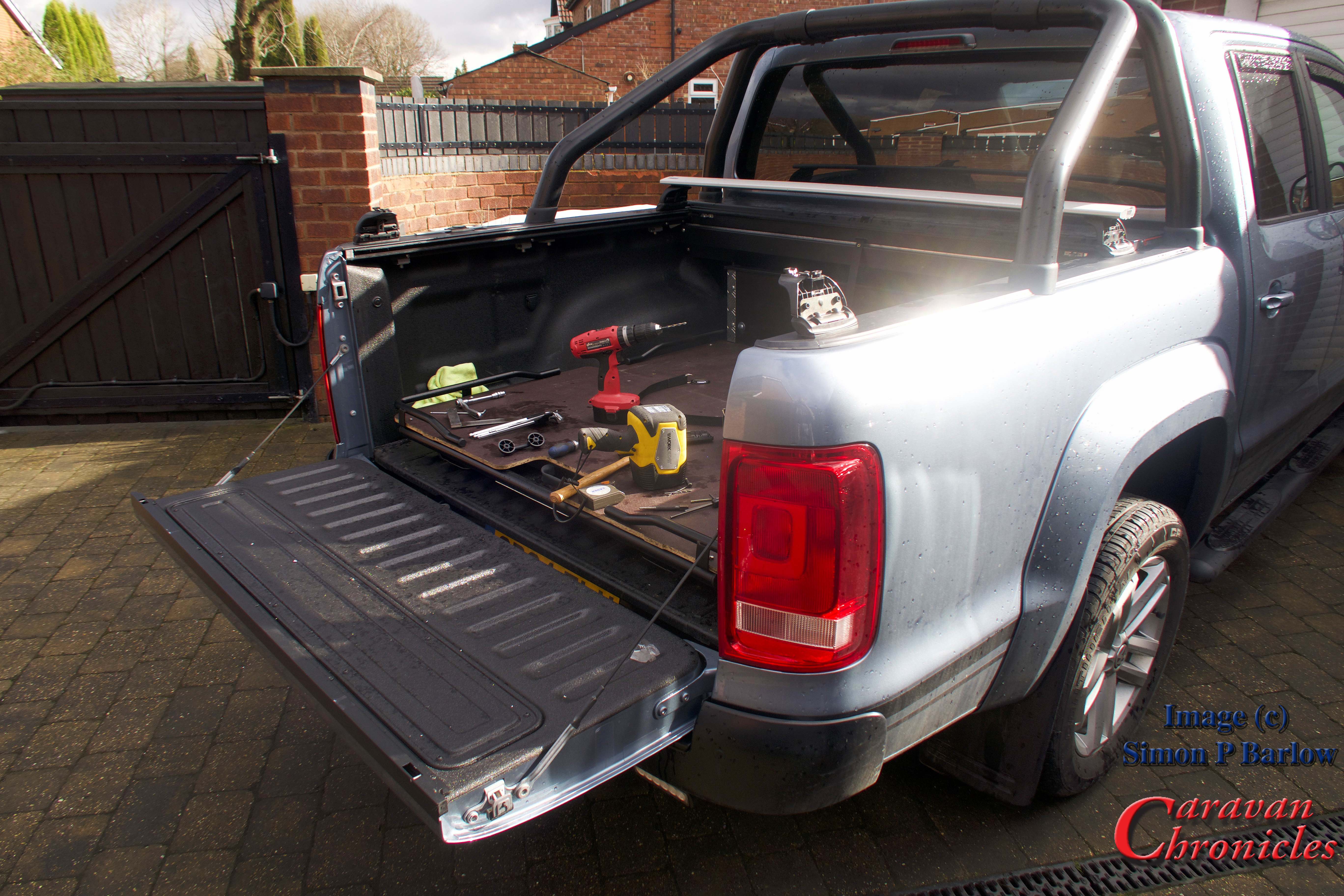
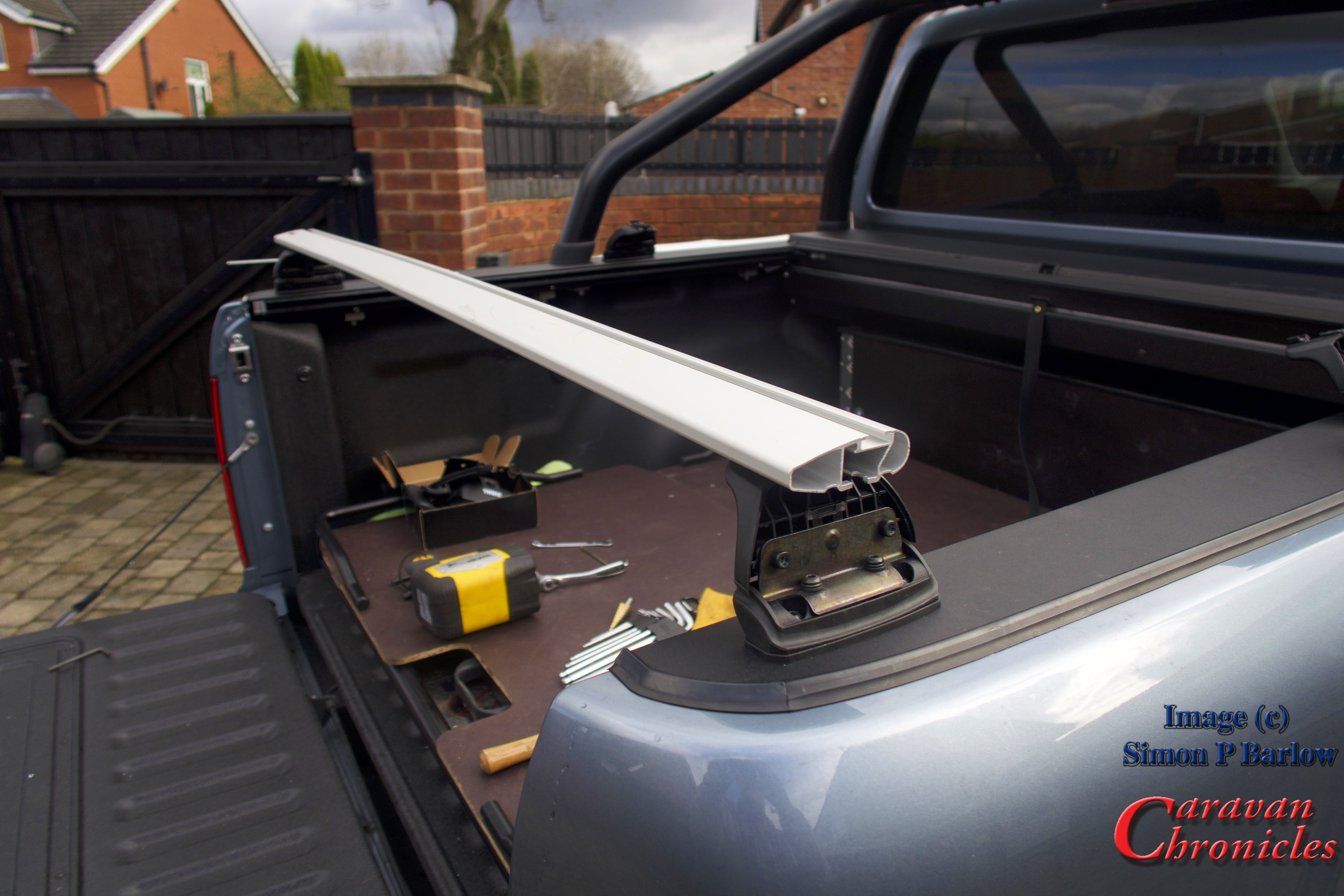
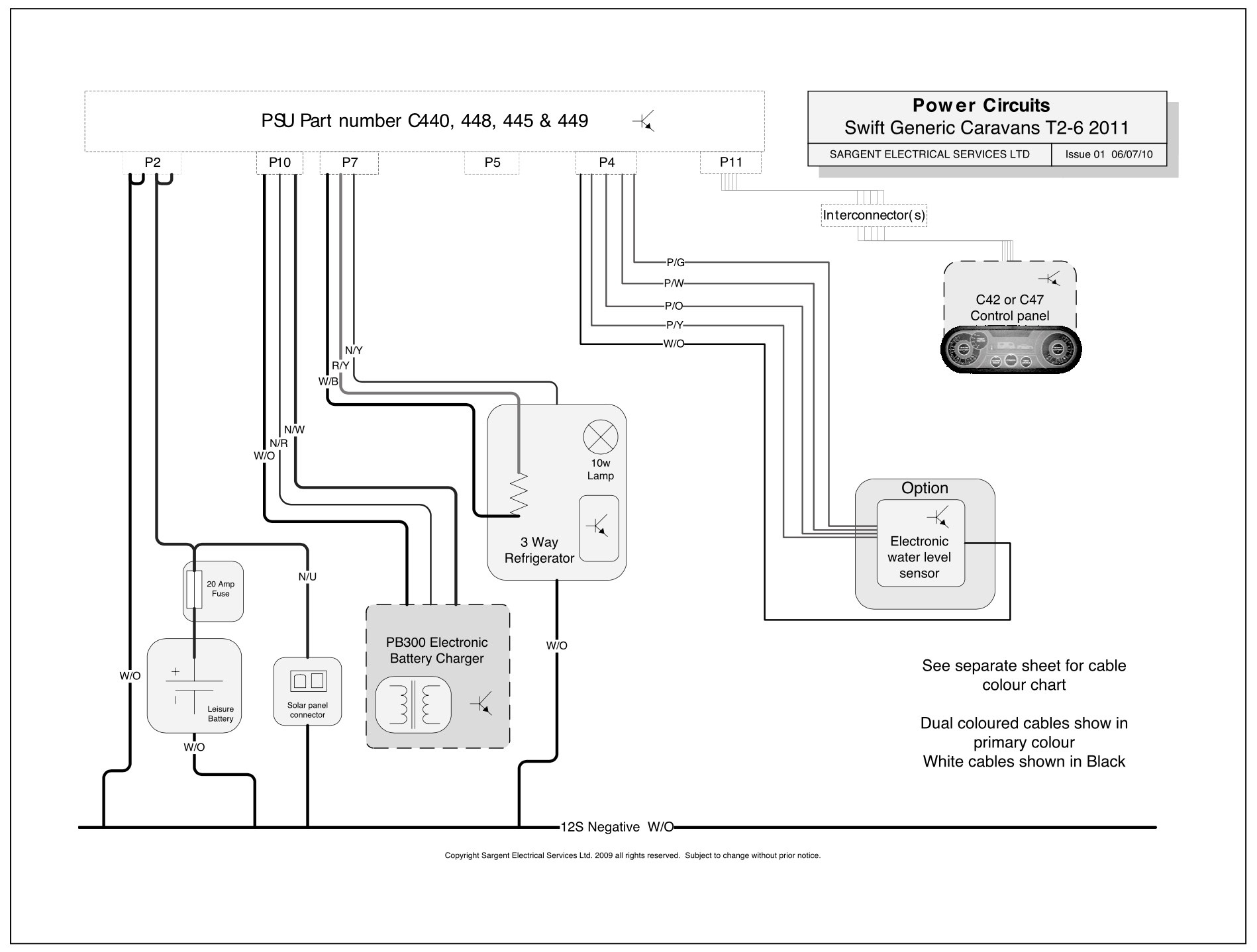
I printed out copies of the wiring diagrams and loaded up the Amarok with everything  I’d need and set off for the storage site. Arriving at the caravan everything was cleared out to give me some space to work.

IMG_1134

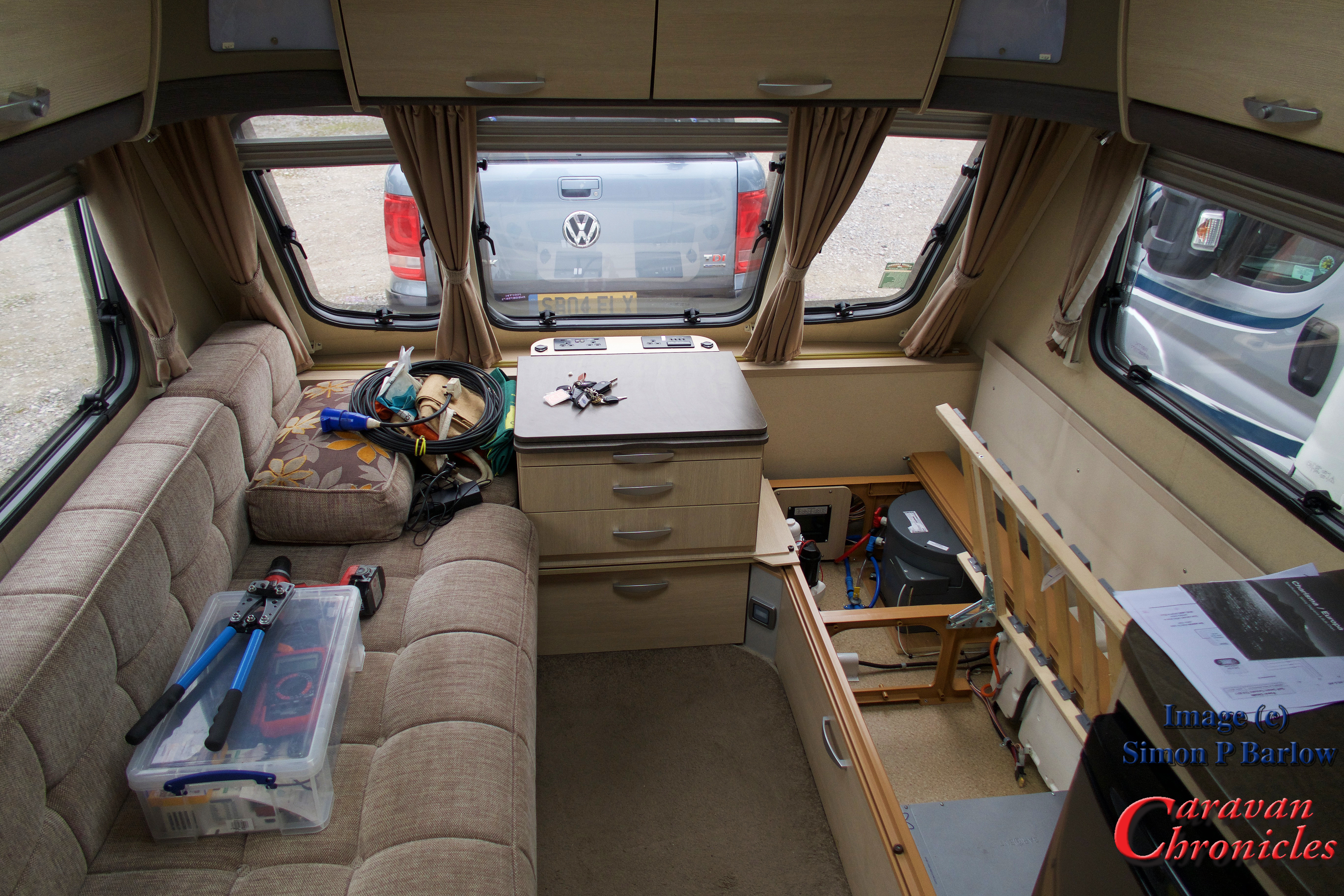
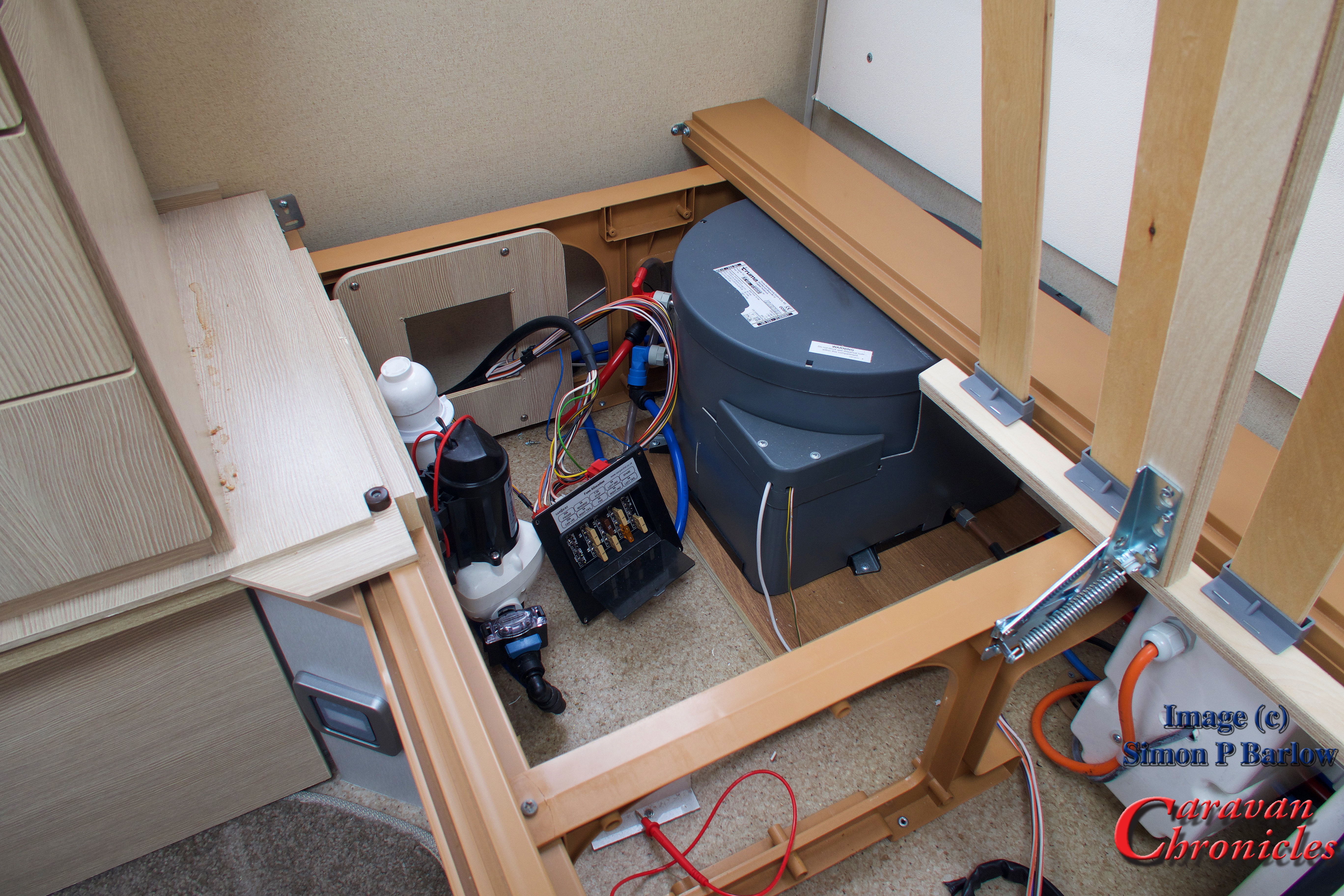
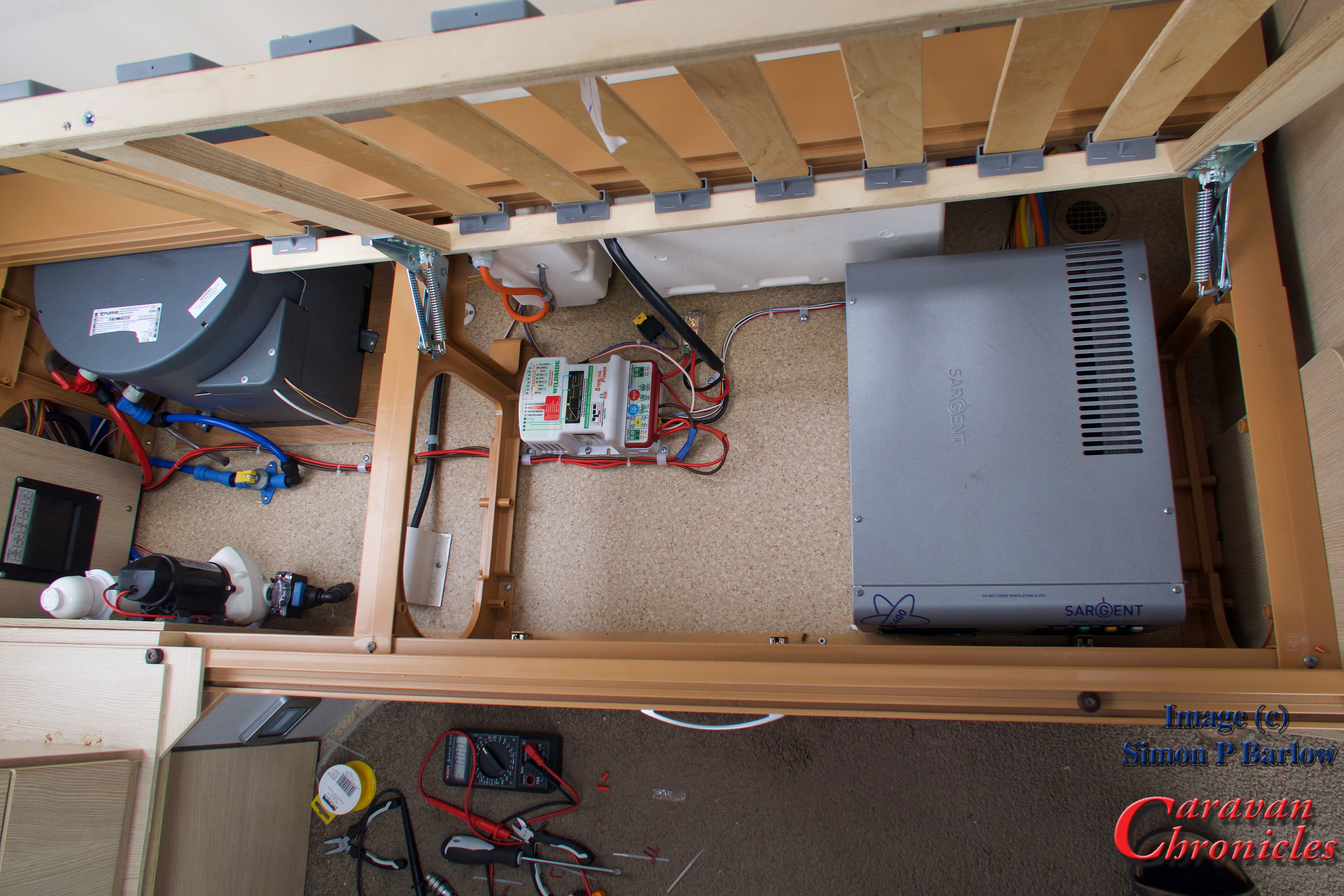
I’d planned to install the unit somewhere close to the Sargent control box as all the connections I’d need could be found here and it was close to the fuse box that connected the lead from the 13 pin plug to the caravan services.

IMG_1136

The fuse connection point for the lead from the 13 pin plug is in our caravan, located right at the front next to the centre chest of draws against the gas locker wall.

IMG_1135

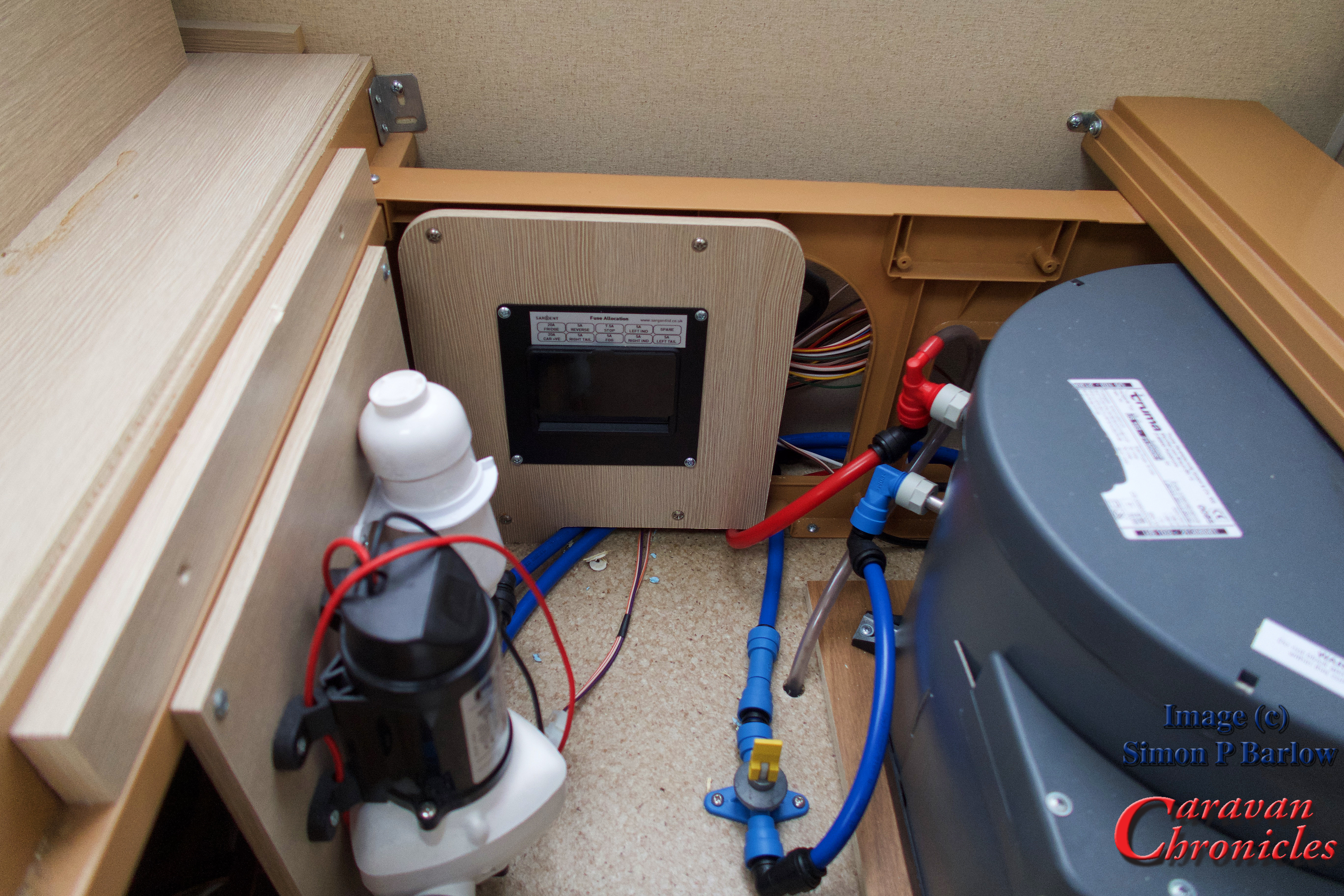
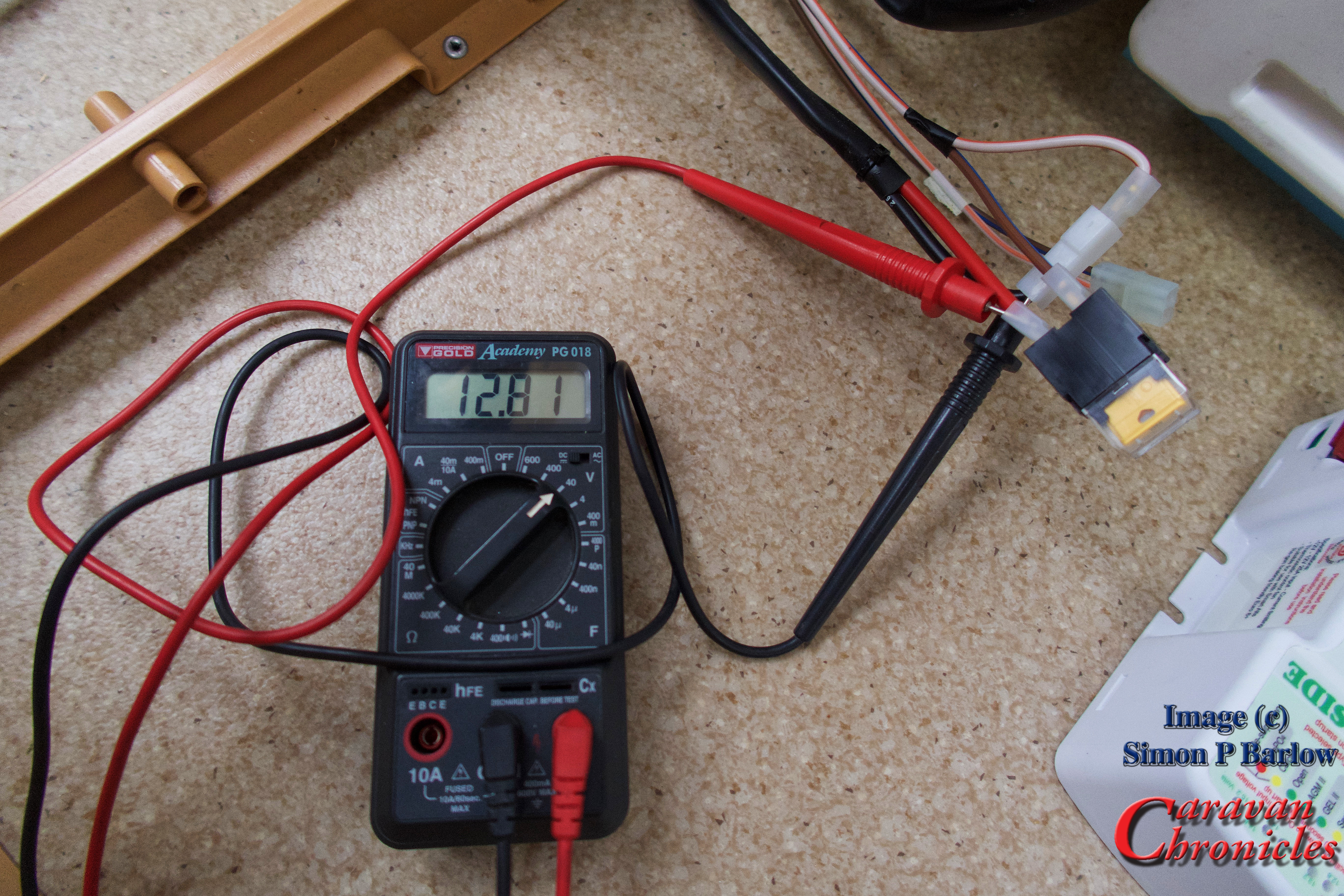
Before starting, I did a quick voltage check on the leisure battery…. 12.81 volts, which isn’t too shabby as we don’t have a solar panel and it had been February 25th when I left the Caravan show at the NEC and the battery was last charged up. Which was   about 13 weeks earlier.

IMG_1139

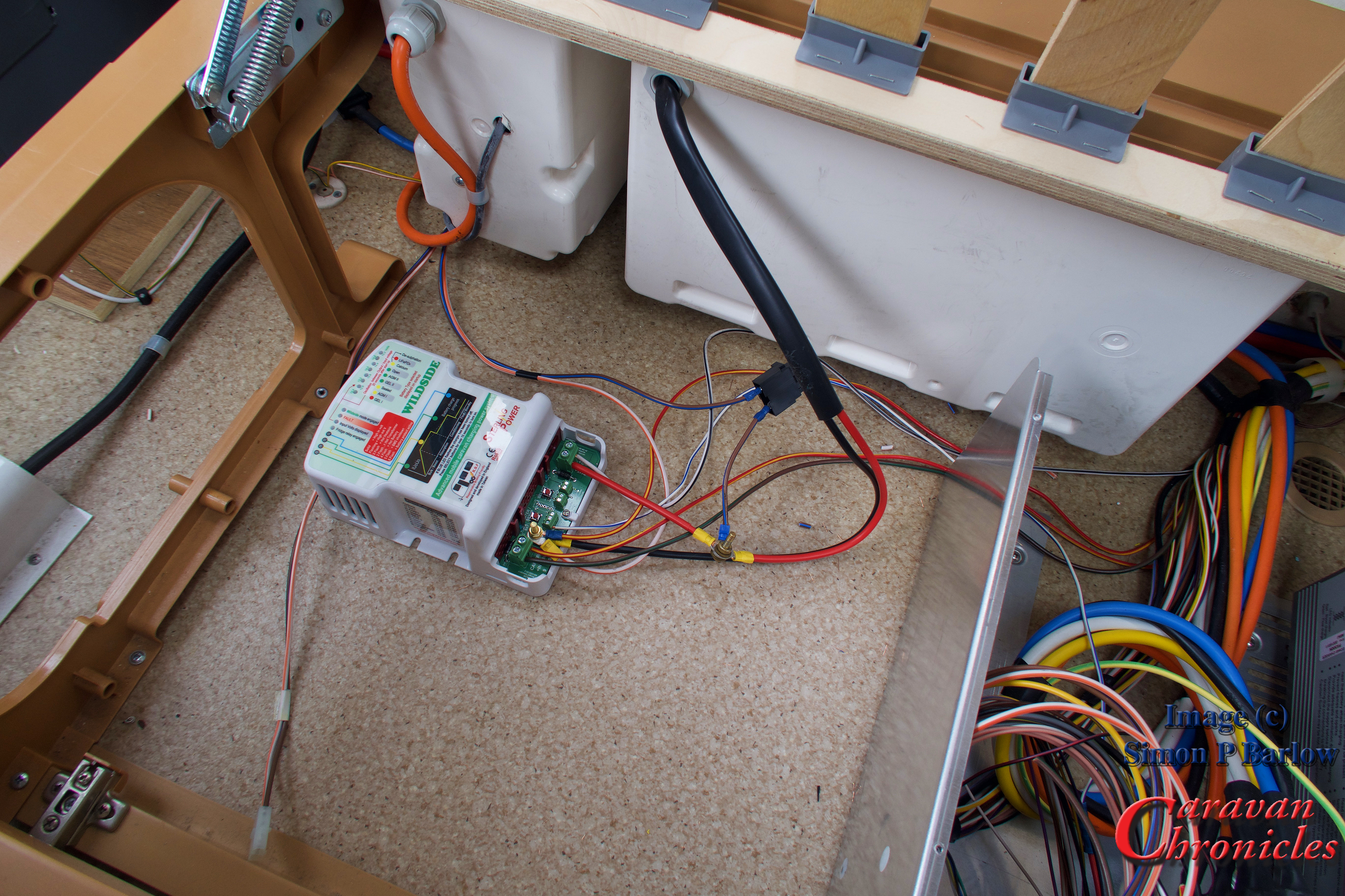
To gain access to the wiring going into the Sargent unit, I removed the 4 screws holding the top cover on and the lid simply lifted off revealing all the connections and as a bonus, service loops in the cable. This meant it should be possible to install the wild side unit without having to do any cable splicing. I did debate at this stage if it would be possible to install the Wildside unit inside the Sargent box… but I decided as I didn’t know the heat gain of the Wildside unit, it might be prudent not to attempt it.

IMG_1137

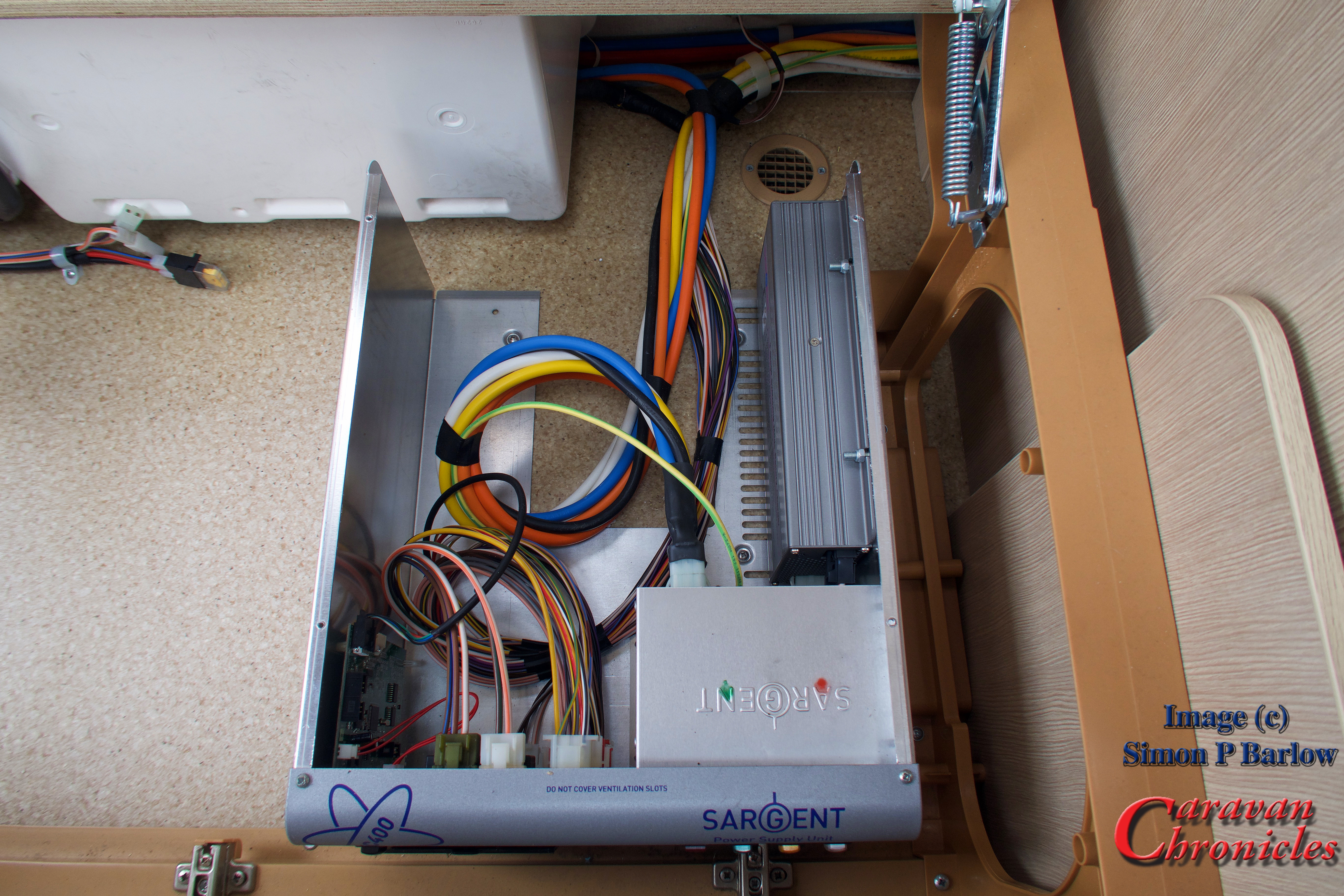
The cables inside the Sargent box are basically separated into two looms. One 12 volt and the other 230 volt which keeps things easy and neat. Also the back of the circuit board within the Sargent unit was printed with each of the plug numbers, so doing all the planning paid off as I could simply find the plug number from my diagram and locate the correct cable easily.

I decided I was going to do a pre-install and connect the Wildside unit up and do a few tests, then once I was happy I’d go ahead and do a full more permanent installation.

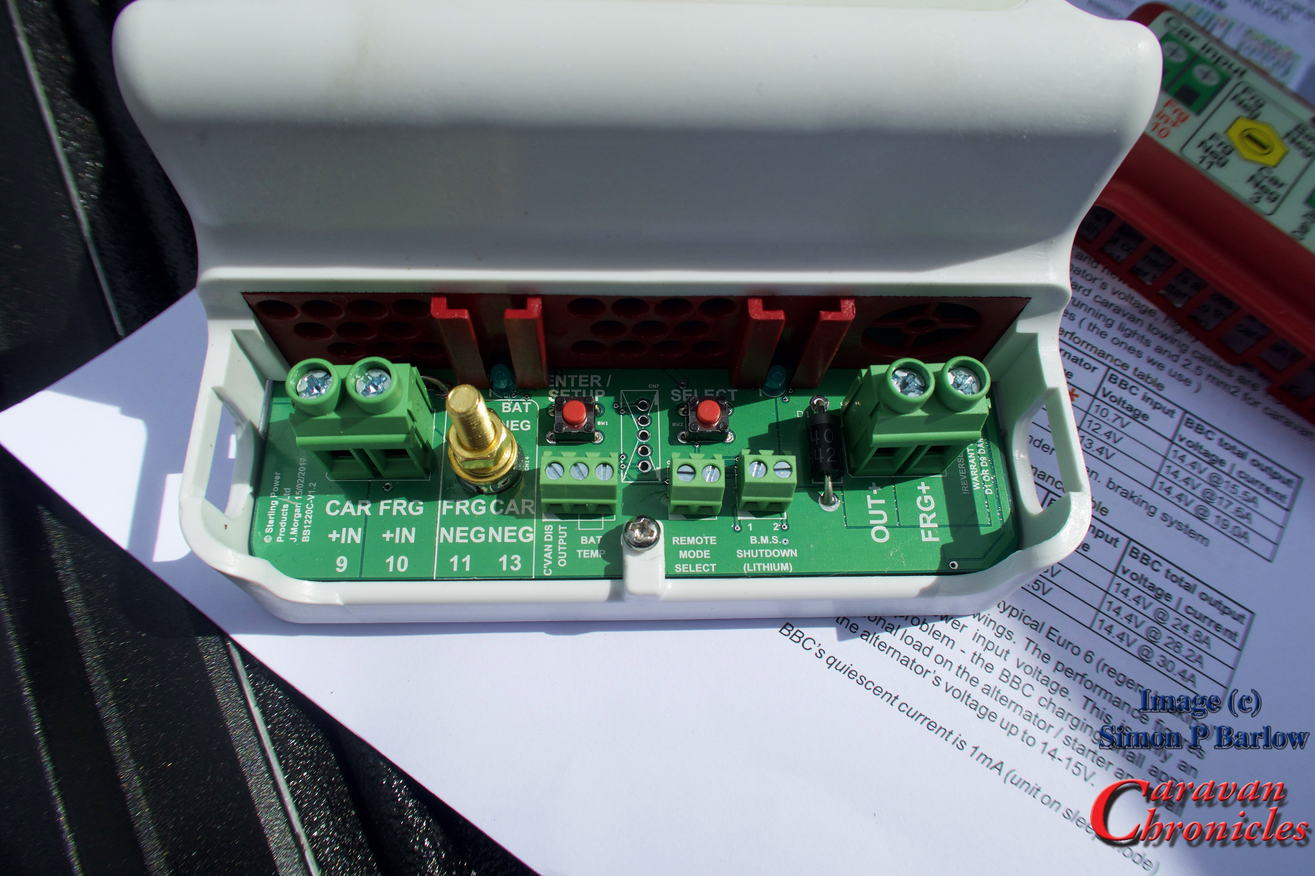
It was simply now a matter of finding the plug I needed, unplugging it, locating the correct wire, cutting it and terminating it in the Wildside unit.

IMG_1140

I cut the cables about 4 inches away from the circuit board plug. This would give me plenty of length to crimp on a sleeve connector and heat shrink if I needed to remove the Wildside unit. As a backup I have also ordered some replacement pin inserts for the plugs so I could always re-terminate directly into the plug.

The next connections would be the incoming feed from the vehicle. 4 cables, two neutral and one positive fridge supply from pin 10 and one positive charging supply from pin 9.  These arrive from the 13 pin plug via the fuse box mounted on the front wall through two 20 amp fuses and to the Sergeant unit. I had trouble identifying the cables as the colours were not as indicated in the manufacturers drawings. So to double check I removed the fuse box to gain access to the 13 core cable where it terminates.

IMG_1141

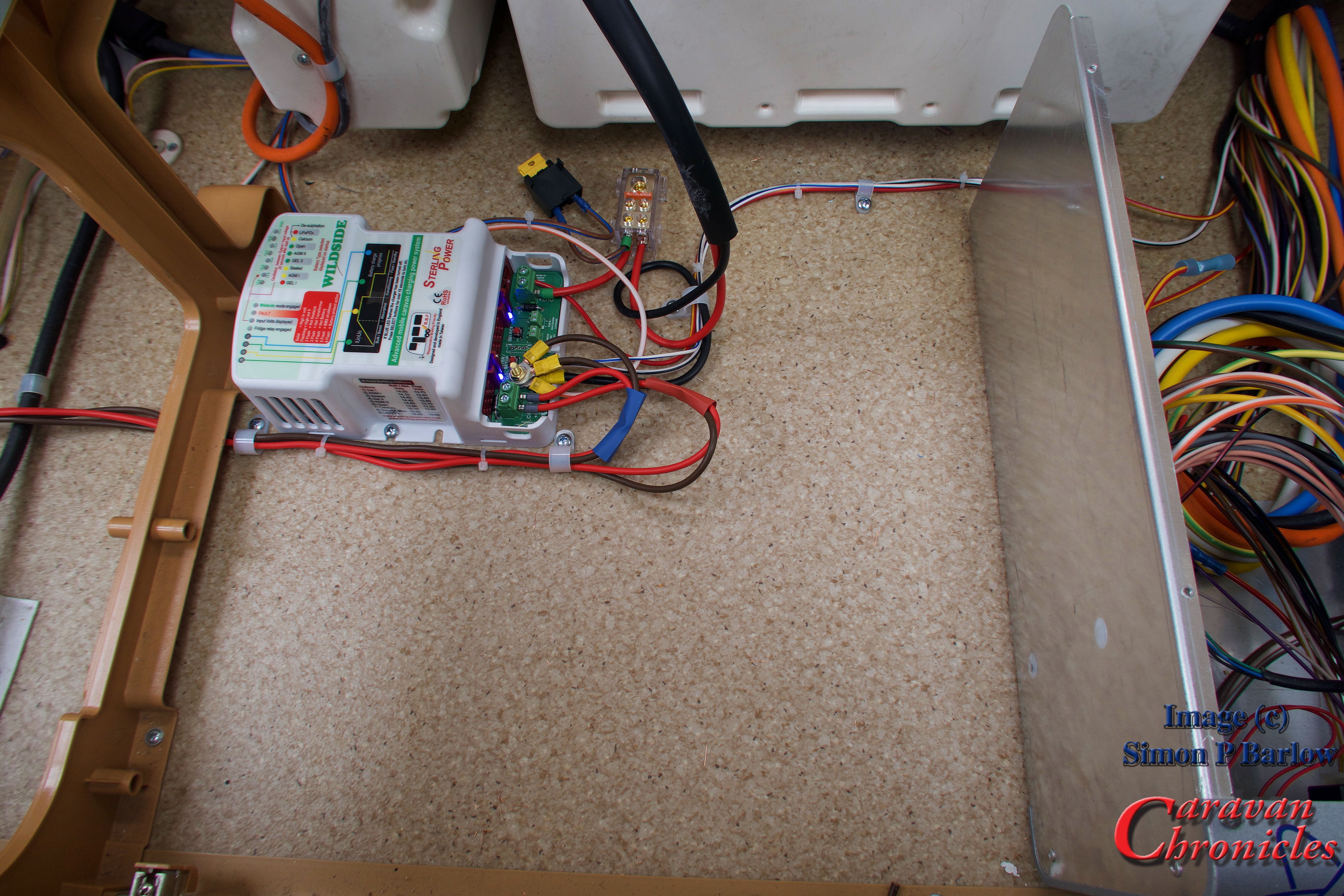
It was easy enough now to trace the correct cables and confirm with my multimeter. So all the connections now made, albeit temporary, I could install the 20 Amp main battery fuse and make sure the Wildside unit powered up OK.

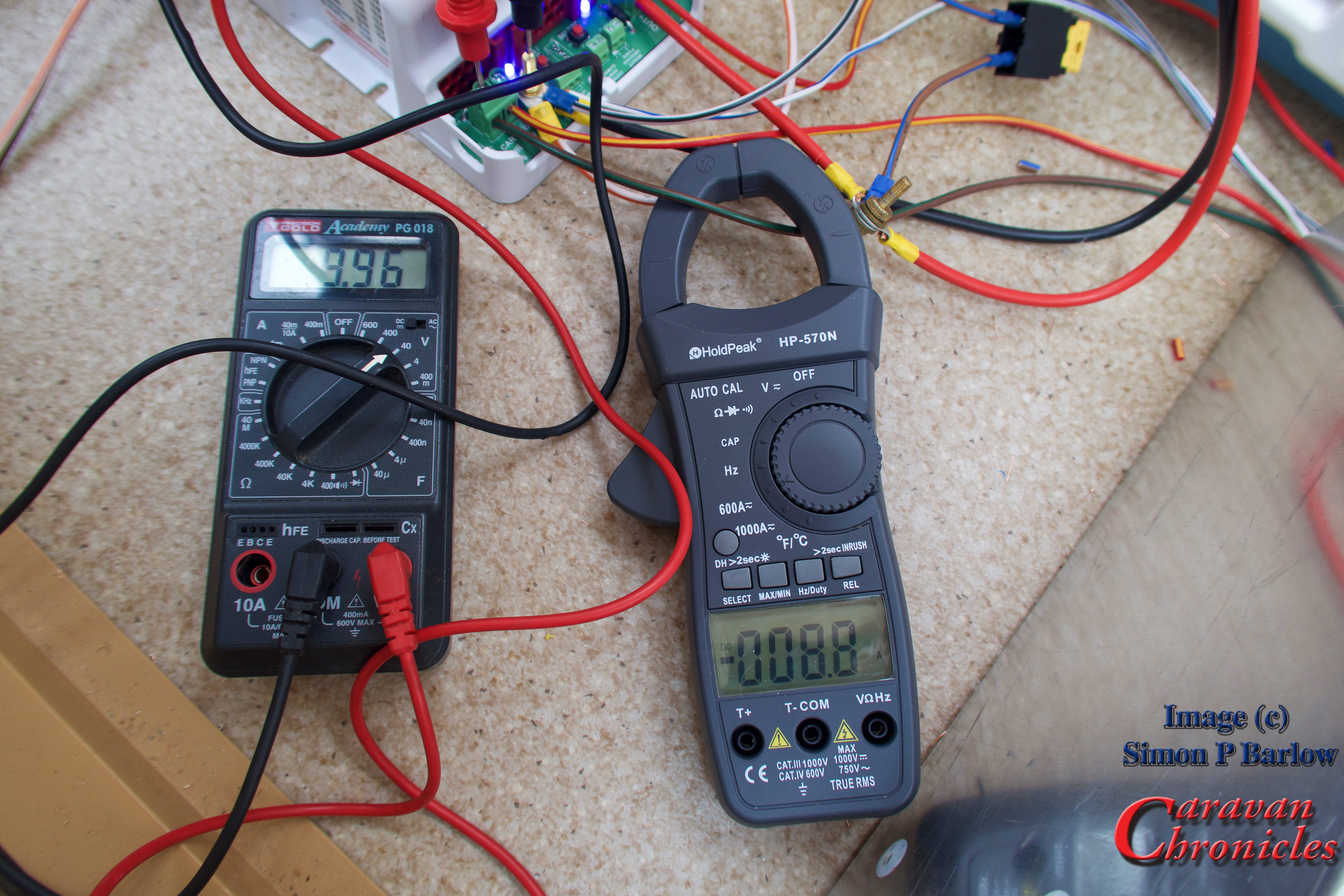
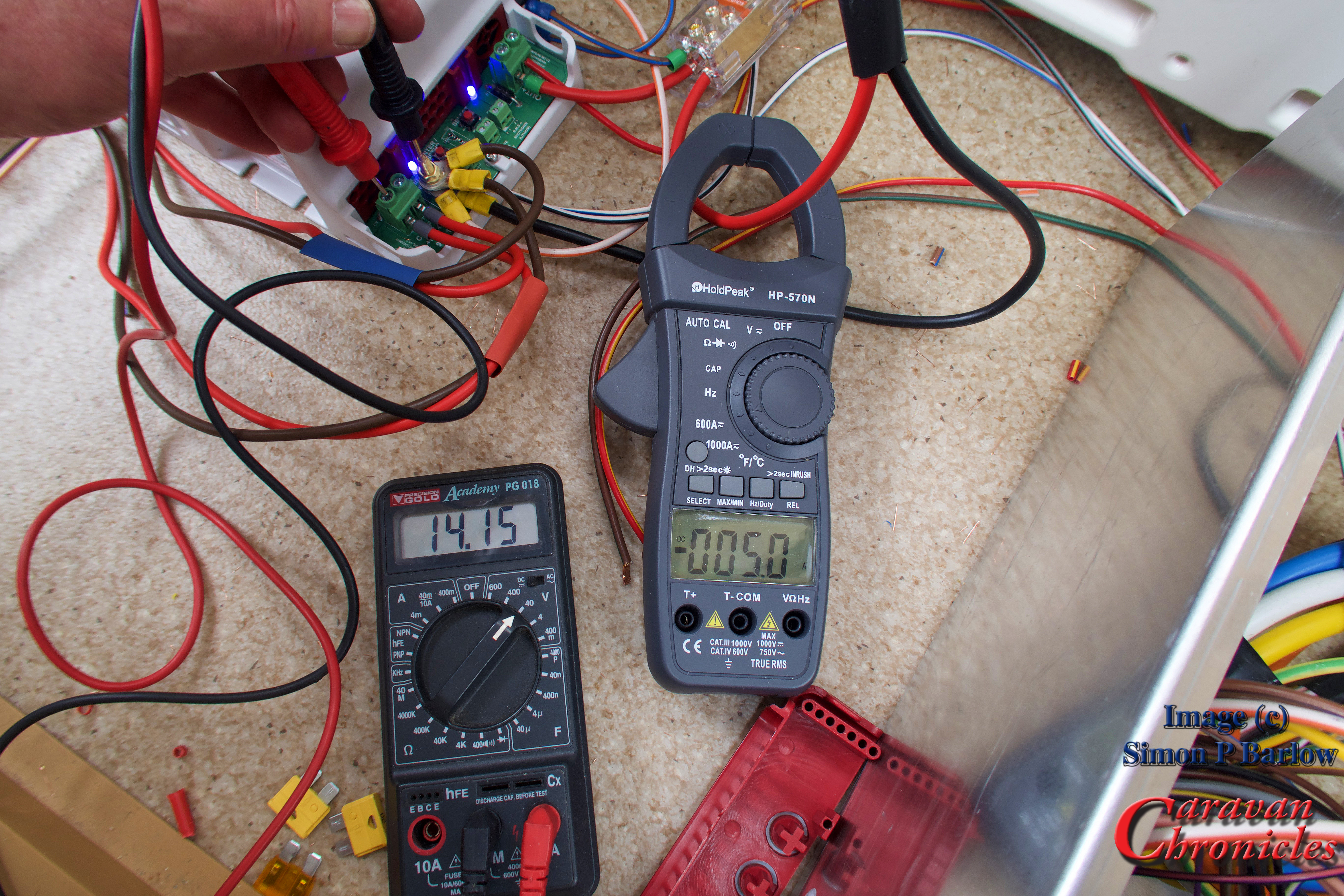
Don’t worry about the brass bolt holding together the three cables, it was so I could easily get a clamp meter on the cables to take current readings.

IMG_1142

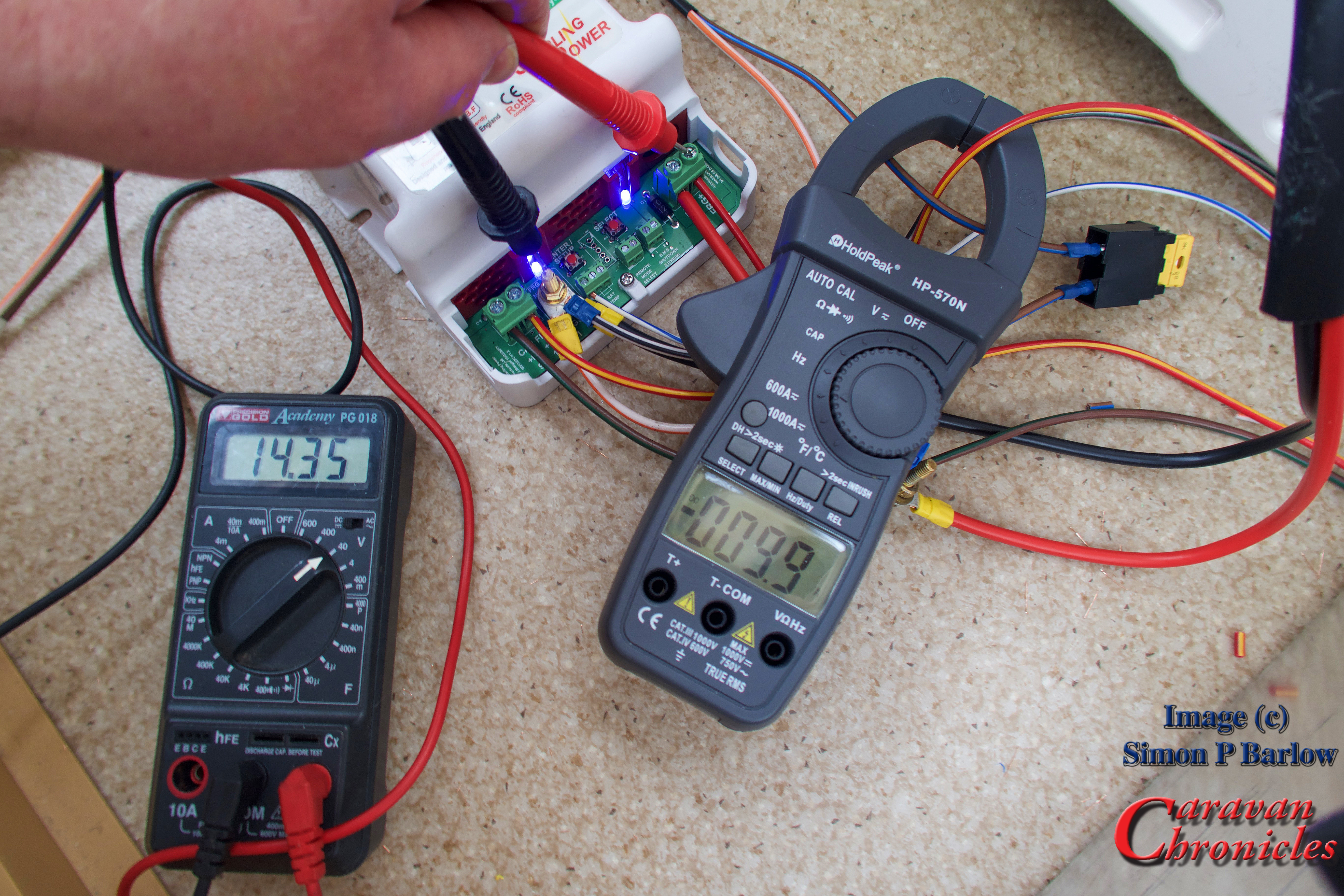
It started up without any problems and so I could connect up the 13 pin plug to the Amarok and start the engine and take a few measurements.

I checked the vehicles voltage and it was sat at 14.5 with run/stop disabled and the engine ticking over. OK how come I had a voltage of 14.5 volts in the vehicle with a Euro 6 engine ticking over? Well the Wildside unit basically makes the vehicle’s ECU think that the vehicle battery requires charging (remember an Euro 6 engine cranking battery will only ever be charged to 80% of its capacity so that regen will always work).

The first reading I checked was the leisure battery incoming link. I had a reading of 9.96 volts and a current of 8.8 amps. That was quite a big voltage drop.

IMG_1143

I moved on to test the incoming fridge circuit. This was showing 9.99 volts and a current of 13.3 amps. I had a big voltage drop somewhere. I checked the voltage at the point the 13 core cable terminates and got a reading of 12.75 volts. somewhere between the incoming cable and the termination on the Wildside unit I was getting a  big voltage drop.

IMG_1144

Continuing with taking some readings, I checked the fridge output and it was stable at 14.35 volts, 9.9 amps.

IMG_1145

A problem with the fridge…

On the original caravan wiring diagram it showed the fridge heating element connected with just two wires and on the face of it this looked simple enough. However when I first connected the fridge and powered up, the fridge came up with error code 10 – no power. There was definitely a supply voltage there and it was indicating a current draw of just under 10 amps. I wondered if the voltage detect circuit was polarity sensitive so swiped the connections round and this cleared the error code. So double check the polarity of the connection if you get an error code 10 don’t assume there is a connection fault.

Thinking cap on…

I decided to stop at this point. Unless I could eliminate that volt drop between the incoming cable and the Wildside unit it was pointless taking any further readings.

The next thing to do would be to eliminate the existing wiring for the leisure battery charging circuit and fridge circuit between where the incoming cable from the 13 pin plug terminated and the Wildside unit. I decided to replace the existing caravan wiring with some 2.5mm² cable.

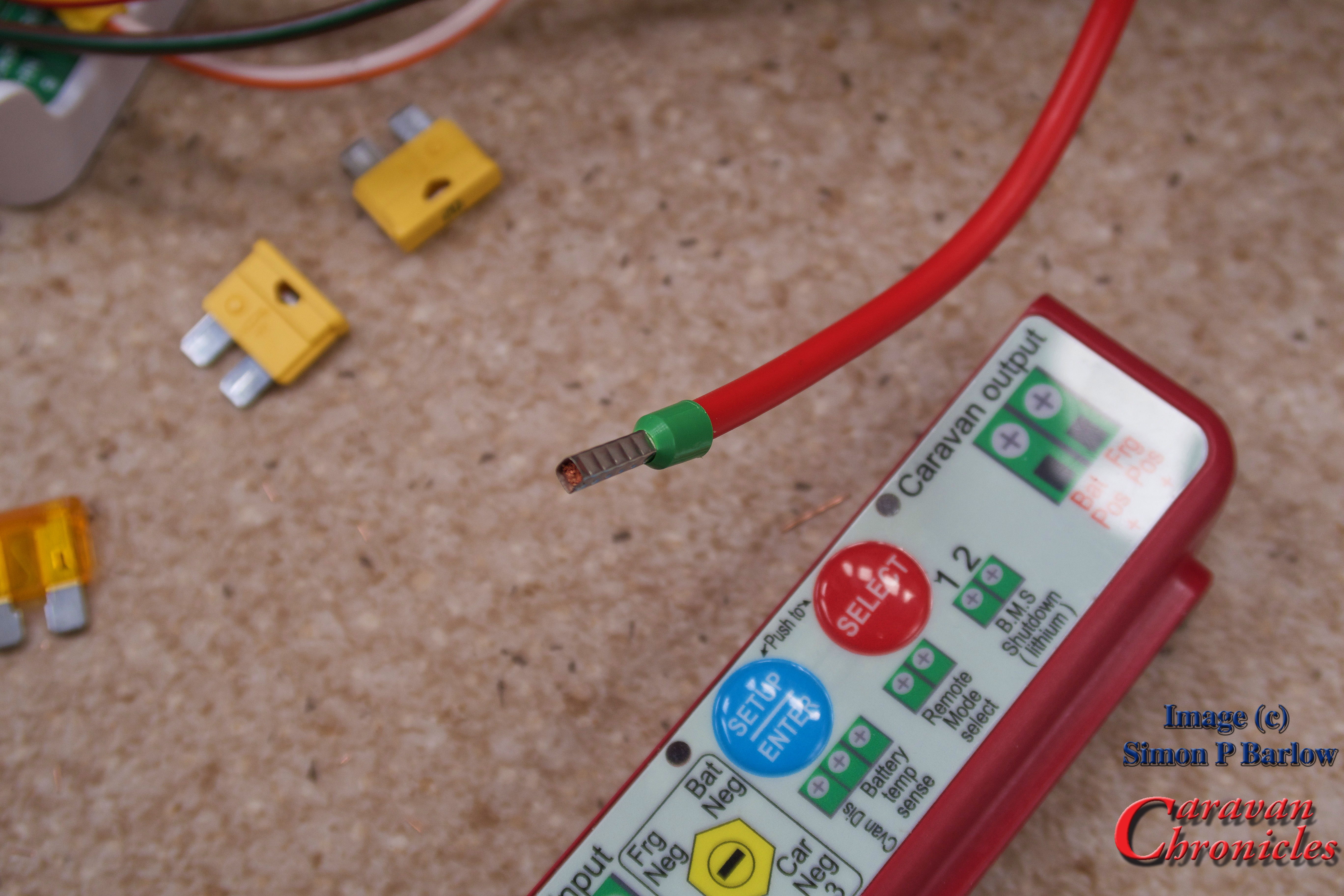
First job was to terminate all the previously terminated cables on the Wildside unit correctly with the correct size ferrule crimped on. When ever you terminate a stranded cable in  a terminal block that compresses the wire, you should first crimp a ferrule on to the cable to ensure a secure connection.

IMG_1148

Next I installed the four new 2.5mm² cables from the 13 core cable to the Wildside unit. I opted to use straight through sleeve crimp connectors to join to the cable coming from the 13 pin plug. I kept the length as short a possible – about 900mm, which resulted in not the best cable route option but I wanted to minimise voltage drop. (remember, the more current you draw through a cable and the longer the cable the bigger the voltage drop!)

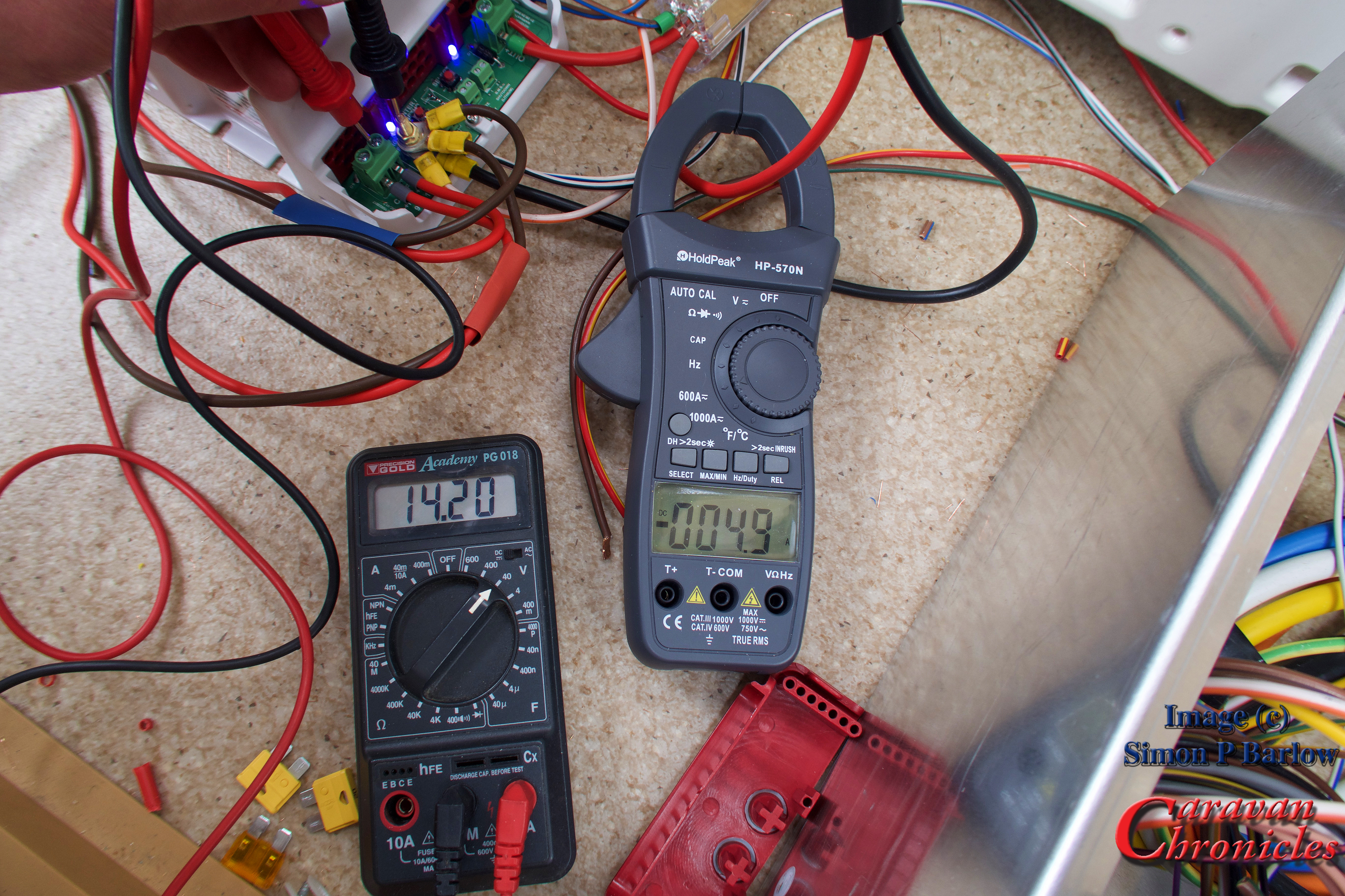
All that done, and the correct terminal block installed for the battery positive lead rather than my brass bolt, I powered up everything and hooked up the Amarok and started the engine once again. With the engine running the vehicle was showing 14.7 volts and I was now getting 14.1 volts on the incoming charing circuit with a current draw of 8.2 amps. Note: the clamp meter in the picture is actually showing the charging current for the leisure battery… 5.0 amps.

IMG_1149

Checking the incoming fridge feed I was reading 14.2 volts and a current of 8.6 amps. Which was a vast improvement over my previous readings. (Note: the clamp meter in the picture below is still showing the battery charging current)

IMG_1150

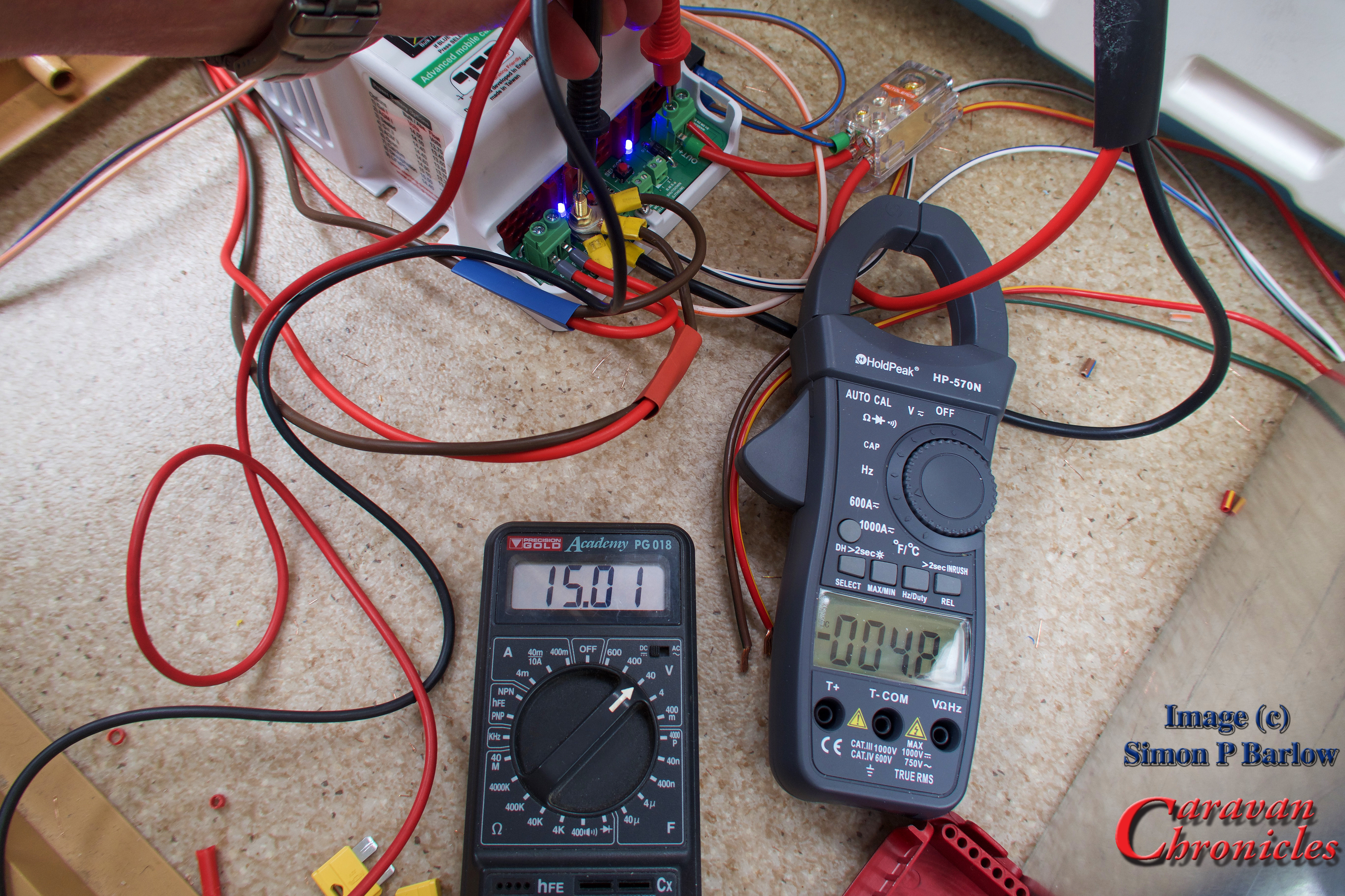
The battery charging voltage was showing 15.01 and 4.8 amps which meant I was at least charing the battery with just the engine on idle.

IMG_1152

Doing a little maths – I was pulling 8.2 Amps via the leisure battery charging circuit and 8.6 Amps via the fridge circuit giving a total of 16.8 Amps. I was supplying 9.9 Amps to the fridge and 5.0 Amps to the battery. A total of 14.9 Amps. The difference would be due to the losses due to stepping up the voltage being supplied by the vehicle to the output voltages of the Wildside unit. In terms of watts – the vehicle was supplying 237.74 watts and the wild side units was outputting 224.49 watts.

This did make me think. As the fridge was now consuming 149.49 watts (its rated at 150 watts) so it in theory should be at it’s max efficiency… did it need to be on all the time? Could the fridge be switched on a duty cycle of say…on for 75% and off for 25%? This would then increase the ability to put more back into the leisure battery, especially useful on short runs.

Speaking to Charles Sterling, I know this unit has been rated on the conservative side and in theory 20 amps can be pulled from each circuit. This would give around 560 watts of power… and in theory about 400 watts available for charging the leisure battery. Will that damage your vehicle? Well as most Euro 6 engines are fitted with 2Kw alternators, there is still plenty of power available.

Finishing up

It was now a matter of tidying up my mess and installing some cable ‘p’ clips to secure everything to the floor. The two sleeves on the cables that come from the 13 core cable are there so I can identify each circuit. Red for leisure battery charging and blue for fridge circuit.

IMG_1157

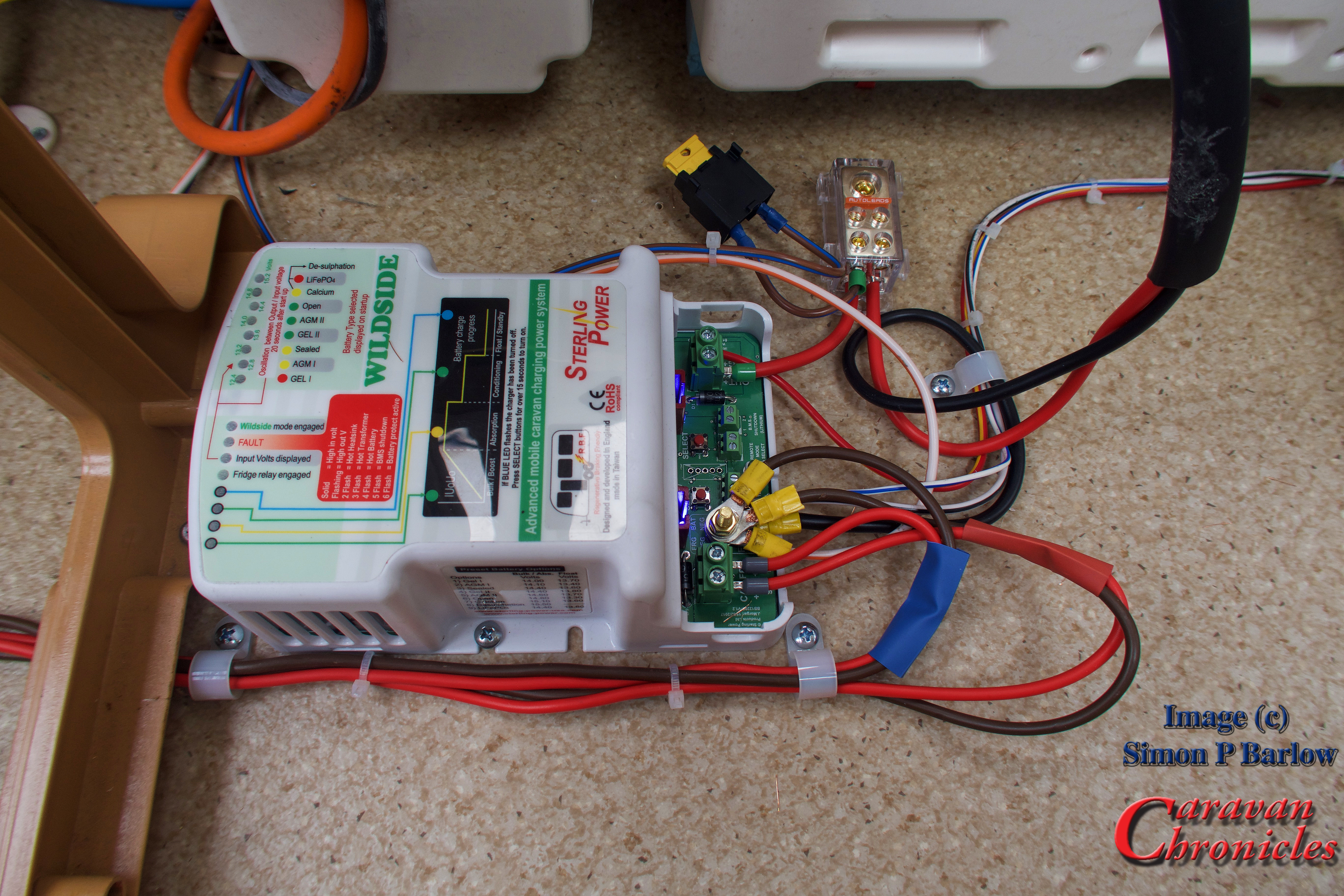
The yellow fuse you can see is the leisure battery fuse. It’s rated at 20 amps and is in circuit between the leisure battery and the caravan services, so pull that fuse and the caravan will be isolated from the 12 volt system. I’ll probably replace that with a circuit breaker in the near future.

IMG_1156

IMG_1161

A couple of things I thought about while doing this install.

The Sargent control box is a lot of wasted space. I recon that it should have been shrunk down to ¼ of it’s current size and probably relocated to somewhere else… maybe under the draw unit at the front of the caravan.

The incoming fuse connection panel too seemed a little flimsy. All it consisted of was a circuit board with multi plug connectors on one side and spade connection soldered on the other for the blades of the fuses to slide into. Some of the soldering looked ‘dry’ and I wondered if this was causing some of the volt drop I was experiencing… that coupled with the multi-plug connections in the loom. I know it makes the build of the caravan easier on a production line and you only need semi skilled labour to install but hey sometimes things like this matter.

Its obvious that caravan wiring is done down to a cost and the minimum standard required. I would have liked to seen some slightly heavier gauge cable for some of the connections. It amazed me that the leads that connect to the battery are 6mm² but drop down to 2.5mm² once outside the battery box and the connection between the two is just a simple male/female spade connection.

The other thing that struck me was how inefficiently the plumbing was done. I’d never really looked at it before, but casting my eye over it I think I could have laid it out a bit better and saved three push-fit connectors.

Who’s this unit designed for?

Well anyone really that has a Euro 6 engine in their tow vehicle or motorhome (if you have a motorhome you need to look at the BB1230 which is a step up again from this) and cares about maintaining their leisure battery.

If you have a motor mover fitted and use it to get your caravan out from its parking spot before you set off and then find sometimes you don’t have quite enough power to position your caravan on your pitch when you arrive or the reverse… your motor mover always seems to run out of steam trying to put your caravan back in its storage area when you return home, the Wildside unit should make sure you always have a fully charged battery and I’m my opinion is something that should be classed as an essential item.

From a lot of emails I have received it would seem that generally people with motor movers seem to be changing their batteries more frequently. A lot of the time when the motor mover stope working or works erratically the advice from the motor mover manufacturer is “you need a new battery” or” its a problem with your battery”. I”m going to throw this out there… I think it may be down to the batteries never really getting a proper charge and sulphating, radically shortening their life.

Alternatively if you do a lot of “Off Grid” (Boon-docking) camping, this will make sure you maximise the charge in your leisure battery to allow you to get the most from it. Especially if you have a Euro 6 engine.

How easy is it to install?

Planning is the key and a modicum of skill in being able to trace cables and terminate correctly. However a lot is going to depend on your caravan, how it is connected and the quality of the original installation. For me it was quite straight forward but the location of the existing components made it easy. Depending on your particular caravan you may end up having to run some additional cabling. Whatever you do, do not cheap-out on cable termination! Buy the right terminals and a good ratchet style crimp tool and make sure any cable you install is a good quality brand of the correct gauge.

Were there any issues?

Nope, it worked straight out of the box.

What next?

Road test! In a few weeks we are travelling down to Glastonbury which is between a 5 and 6 hour tow and I’ll be taking readings during the trip to see how the battery is being charged and the fridge temp. Just for the pure fun of it….. I’m going to try to make ice cubes in the freezer so we have ice for our drinks when we arrive! I’ll let you know how I get on.

Looking forward.

The biggest problem really is the fridge. A three way absorption fridge is probably the single most inefficient way of chilling anything. Whether its powered from 12 volts, 230 volts or gas. Its far more efficient to use a compressor fridge.

Now a 230 volt compressor fridge is relatively cheap when compared to a three way absorption fridge, great for when you are on hook up, but now imagine being able to run it via an inverter while you are driving or off grid from your battery. As they only run short periods and take less power to run. Coupled with the fact they don’t run continuously like an absorption fridge. It would be possible to do away with a 3 way absorption fridge completely.  As we now have a sensible way of charging batteries, and given the fact the price of modern lithium battery technology is dropping all the time I don’t think technically we are far off making the transition. Its just down to the caravan manufactures…. so don’t hold your breath.

Contact:

Sterling Power

Stuff I used:

You can find links to all the crimp terminations and tools that I used in the Caravan Chronicles Shop


Getting All Charged Up – Part 2…

Tags

, , , , , ,

Planning the Install

Remember the Six P’s… “Proper Planning Prevents Piddling Poor Performance”… or something along those lines! Before we start hacking away at the multitude of cables (and my email inbox fills up with help requests) we need to pull out the relevant electrical schematics from the handbook. Our caravan is a ‘dealer special’ based on a 2011 Swift Europa 550 fitted with a Sargent PSU.

We can see from the schematic below that the 13 pin plug enters into the caravan and terminates with two connectors – FB6 and FB7 on fuse unit C44 which in our caravan is located just next to the front draws near the water pump. FB6 is all the road lights and we can ignore this.

Socket Connections

The cables we are interested in are from pins 9,10,11 & 13 which are coloured Orange, Slate Grey, White/Black and White/Red respectively and terminate in connector FB7. We need to now look for these leaving the Fuse Unit and heading off to the PSU.

The most likely candidate will be connector FB2 with four cables going to connector P1 on the PSU. If they are all 2.5mm²  it’s a good clue these are the ones we want. We will need to check these with a multimeter though to be sure. The colours have changed too so we will need to confirm what the new colour is for each circuit.

Socket Connections 2

So that’s the input side of the Wildside potentially sorted out, now we have to find the fridge connections. Looking at the schematic for the Power Circuits we can see that the fridge is connected via four cables. One directly to Neutral and the other three to P7. We can also see from this schematic that the leisure battery is connected to P2 via a 20 Amp fuse. This tells us two things – the wiring is rated for 20 amps and we will have to upgrade the cable size from the Wildside unit to the leisure battery.

Fridge Circuit

For the fridge… We are interested in the two cables that power the heating element and on the drawing they are coloured W/B and R/Y (White/Black and Red/Yellow) and originate from connector P7 on the PSU.

Fridge Circuit 2

We have now identified on the schematics the cables we need to look for and where they run from and to. Next step is to create a new schematic using the information from these two drawings to show how we are going to connect in the Wildside unit.

To The Bat Cave…. err Drawing Board!

If you are handy at using a drawing package such as Sketch-Up or similar (I use “AUTODESK® Graphic” on my MAC) you can have a go at drawing it out, or simply just use a sheet of paper. The important thing here is you DO draw it out.. this is not an option, its a mandatory task!

TIP: If you are drawing this out by hand on a sheet of paper, it might help to photocopy your caravan schematics and cut out the relevant sections… like the fridge and stick them to your drawing to make it easier.

So here’s my efforts….

Wildside Wiring 01

If you remember in part 1 I said we will need to make five connections…. not including the neutral. Well we have the five connections. After looking at the layout I decided not to cut the current leisure battery connections to upgrade, but to install a new Positive and Neutral cable alongside the original cables. This will mean however I will need to drill a new hole in the battery box and install a sealed cable gland.

The three cables that we cut on P1 that are now unconnected should, in theory not be part of any circuit. However to be sure I’m going to terminate both the neutral cables (originally connected to Pin 11 and Pin 13 to the neutral point on the Wildside unit.

The cable that was originally connected to Pin 9 I’ll just crimp on a blind connector and secure out of harms way. I am not sure if this might need to be connected to a +ve supply. There are a couple of things that I’ll need to check, for example, the toilet flush always works when the caravan is connected to the tow vehicle – with or without the engine running ( handy if a quick P(it) stop is required!).

Now… To The Bat Cave!

Well it might be a couple of days as I have just ordered a few bits and pieces I don’t have in stock in the workshop… and I’m still procrastinating whether to do the install as a video to accompany my written ramblings.

Coming up in part 3. I attempt not to destroy our caravan, do a lot of crimping, consume a lot of coffee and I may be swearing a lot on camera!

Getting All Charged Up – Part 1…

Tags

, , , , ,

If you are a regular reader you may remember a couple of posts I wrote about leisure battery charging in caravans and motorhomes (Smart Alternators: how they affect Caravans and Motorhomes…. and NEC Show Roundup – it’s all technical…) and I linked to a few videos that Charles Sterling from Sterling Power has produced covering charging topics and Euro6 engines. At the recent NEC show Sterling Power were featuring a new product that would soon be available that would solve all the issues for caravan owners that were experiancing towing with vehicles that had “smart alternators” which were are standard on Euro5 and Euro6 engines and the issues around regenerative braking on Euro6 engines. Charles promised to send me one of the first pre-production “Wildside” Battery to Battery chargers specifically designed for caravans.

IMG_1127
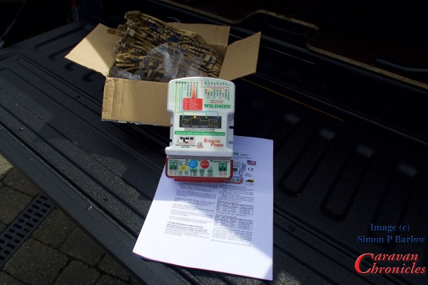
A couple of days ago I was excited to receive   a package from Sterling Power containing one of the pre-production new “Wildside” units. The unit itself is robustly constructed and weighs in at about the same as a bag of sugar – 1Kg.
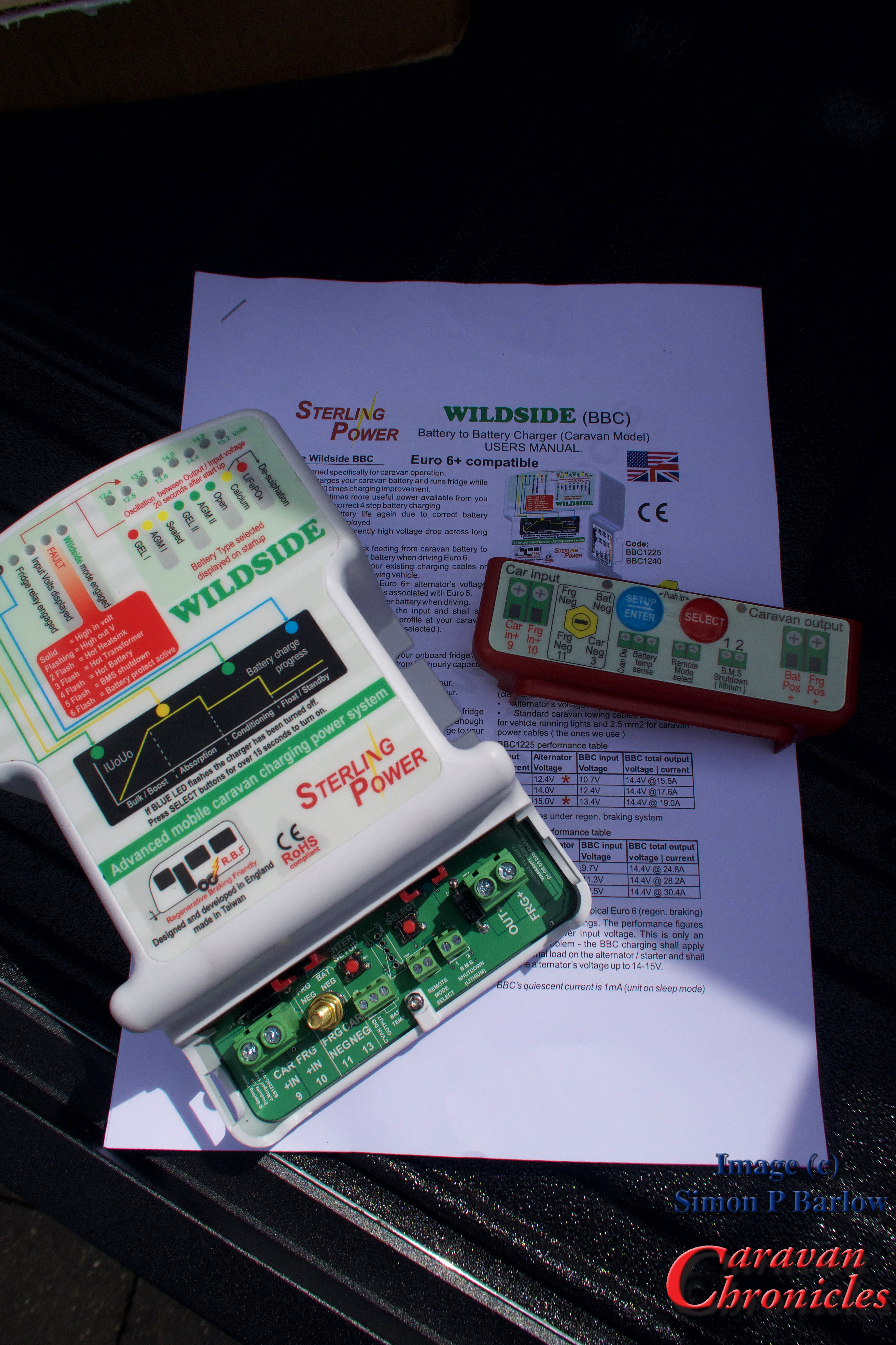
It comes with a comprehensive 11 page instruction/installation manual that goes through all the steps that you need to install the units and what all the various lights and connections are on the unit itself. For anyone that is familiar with my electrical drawings, Sterling have based their installation drawings on my format so are easy to understand (in my opinion!).

I’ll state now for the record, Sterling Power have sent me this free of charge to install and evaluate and that is what I’m going to do, but I will be honest and tell you if I think there are any issues with the installation or the unit in the way that it operates.

IMG_1131

Looking at the connections for the unit it all looks straight forward. The circuit board is labelled  exactly as the drawings in the installation manual which is reassuring and the manual goes into the various functions of each connection and the programming of the unit.

Why this unit?

Since we had changed from using our 2006 Land Rover Freelander HSE as our primary tow vehicle to our 2016 VW Amarok Atacama I had noticed that our leisure battery was not getting close to a full charge even after towing for a couple of hours. We don’t have a solar charging system installed and relied on the tow vehicle and EHU when on site to keep our leisure battery topped up. I knew about the limitations of smart alternators and have written about them before and answered lots of emails about problems readers were now experiancing. Up to this point I really didn’t have an answer to most of the problems and I was considering going down the same route as our Australian cousins and installing some hefty cables between the tow vehicle and caravan, connected together with Anderson connectors. Works fine down under and would do here, especially coupled with one of Sterling Power’s B2B units which I had been looking at.

Now this would be ideal for us, but anyone who tows using a company car, a lease vehicle or a vehicle on a LP scheme can’t just go ahead and install stuff willy nilly. Unless it is done right, it has the potential to be a bit of a ticking bomb as well and  if I was going to recommend it as a solution there are very few people with experience to do an installation of this type. I have seen some right botch jobs on heavy-duty cabling by so-called “professionals” when installing simple winches and dual battery systems on 4 x 4 off road vehicles. Using a lump hammer, cold chisel and block of metal is NOT the professional way to crimp battery cables!

I was looking round to see if there were other options and talking to the chaps on the Sterling Power stand at the show told me they had a product in development that might just be the solution…. and here we are!

How does it work?

I’m not going to give you chapter and verse on the internals (some of that would be guessing on my part and some is propriety information anyway) so I’ll simplify it as much as I can.

In current tow vehicles you have two connections that supply power to the caravan – one for the fridge which is only live when the engine runs and one for charging the leisure battery which is usually live all the time.  Now the problem is that as it’s quite a distance from the front of the vehicle where the battery and alternator are to where  the leisure battery and fridge are located in the caravan. The size of the cables providing the connections are key to how efficient it all works.

Nearly all good quality tow bar wiring uses 2.5 mm square (2.5mm²) cable for these circuits and they connect between the tow vehicle and caravan through a 13 pin plug and socket (or 12N & 12S in older vehicles). The problem with all this is down to good electrical ‘laws’. In essence the more current you draw through a length of cable the greater the voltage drop ( I go into a bit of techie detail about it here… Understanding Cable and Cable Sizes ) Some people go to the lengths of re-wiring the circuits in 4mm² or even 6mm² cable, which was OK up to a point… usually the point which is the connection between the vehicle and caravan. With the traditional installation what you end up with is two circuits that the voltage is usually too low to provide a good charging capability for the leisure battery and the fridge circuit that might or might not, depending on voltage drop, have some spare capacity but you can’t use it to charge the leisure battery.

Back to the Wildside unit…

What the Wildside unit does and this is really clever, is it takes over the two power circuits, aggregates them and manages the output. It draws the maximum current available through each of the two circuits and provides an output for the fridge always at the correct voltage to maximise the efficiency of your fridge and protect it from the voltage fluctuations inherent with Euro6 and Regen engines and any spare capacity on this circuit it added to the leisure battery charging circuit, steps up the voltage and provides a separate output via a four stage intelligent battery charger to maximise the charging capability to your leisure battery.

This is a very very simple one paragraph explanation, it does have a few other tricks up its sleeve though.

One feature is the “Remote Mode Select” switch option. This allows you to install a switch that will allow you to turn the unit to “Wildside”, “Boondocking” or “Off Grid” mode and run the fridge as though it was being powered from the vehicle. It is actually being powered from the leisure battery.

Take note though… Most caravans and motorhomes are fitted with absorption fridges which use a heated element that is constantly on to make the fridge work. However some motorhomes ( I don’t know of any caravans) are fitted with the more expensive and vastly more efficient compressor fridges which work exactly like your fridge at home but can’t run on gas. If you are camping off grid for a few days with an absorption fridge, then run it on gas. However if you are worried about your fridge not maintaining temperature on an hours ferry crossing or on a euro tunnel crossing then you can use the switch to keep the fridge running. The period you can power it will depend on the capacity of your battery(s)… I would not advise using it with and absorption fridge on a battery bank with anything less than 110Ah capacity.

If you do use this feature on the Wildside unit, it will protect your battery bank from discharging past the safe point by turning off the fridge when the voltage reduces and reaches a critical point that would damage your battries.

You also have the ability to specifically select the type of leisure battries you have installed – GEL I, GEL II, AGM I, AGM II, Sealed, Open, Calcium, LiFePO4 to get the correct tailored charging and maintenance program for your battery bank.

If you are fortunate to have lithium leisure batteries there are a couple of other connections you will need to check out too.

Installation Considerations…

We know what it does so how do we connect it. Well this is where it could get messy unless we have a plan.

IMG_1132

In essence, what do we need to do? Well we have to cut and divert the incoming pin 9 and pin 10 into the Wildside unit and connect one output to the leisure battery. We also need to disconnect the fridge from the caravan’s original control box and reconnect it to the Wildside unit. As the habitation relay is usually buried inside the original control box we need to be able to control this from the Wildside unit. There is a terminal for this (“CVan Dis Output”) but what do we connect to this to make the habitation relay operate correctly?

The original Pin 10 lead that we cut and diverted into the Wildside unit, the other end of this still goes into the installed control box and this will operate the habitation relay. Remember we disconnected the fridge power lead from the installed control box and reconnected it directly to the FRG+ output on the Wildside unit so all it does now is operate the habitation relay.

So summing up, we have to cut 3 cables and re-terminate 5 ends into the Wildside unit. This of course does not include the neutral connections which will be easy and straight forward.

Other Considerations…

The installation of the Wildside unit must be easily reversible so it can be moved to another caravan at some point in the future.

We must also use the correct size cables to connect to the leisure battery as we will now be charging at higher currents than was possible before, the original cable that was installed in the caravan to connect to the leisure battery may not be of a sufficient rating.

We must document the changes properly so that at some point in the future someone can follow what we have done incase they have to fault find.

We must make sure all the connections and general installation are done to a high standard to ensure the installation is safe.

Finally we must be able to do the install without invalidating any warranty on the original installed control unit (i.e. not opening it up) and retain functionality of all the elements of the caravans electrical system. It’s no use installing the Wildside unit if half the electrical features of you caravan don’t work afterwards!

IMG_1130In Part 2…

In the next part I’ll go through the manufacturers electrical schematics of the caravan and show how to find and trace  which cables we are going to look for when we do the install and how we produce a simple drawing showing the changes.

I’ll also come up with a quick check list for all the additional bits (cable, terminals etc) that we will need for the install.

They Say Things Come in Three’s….

Tags

,

… well I hope they don’t!!

Number One. We were supposed to go to York a few days ago for a five-day break. However that got scuppered at the last-minute by one of our Siamese cats. Polo who is 14 years old suddenly decided he was not very well and it looked like it could have been touch and go and would have warranted that sad last trip to the vet. Something we absolutely could not ask our long-term cat sitter (and house minder) to make. However as it was the sunniest week we have had so far (just our luck) he decided rally round and he’s now fine.. or as fine as a 14-year-old Siamese can be.

Number Two. Last night while clearing up after our evening meal, I was finishing the washing up and Sue took out the kitchen rubbish to the bin. I watched her pass the kitchen window en-route to the bins which are the far side of the vehicles and out of view. After about five minutes or so She hadn’t returned and I guessed She might have been giving our next door neighbours cat a bit of a polish as it does drop in to our garden from time to time to say hello. I sat down in the lounge and thought Sue was being a particularly long time and went out to check. Continue reading

Fit2Go Tyre Pressure Checker…

Tags

, , , , , , ,

Back in December last year I did a write up and little video with Andy Harris from RoadPro about the Fit2Go tyre pressure monitoring system. In the video he promised to send me one of the new Fit2Go Tyre Pressure Checker units as soon as they were released. Well Andy kept his word and yesterday I received a little package from Road Pro.

IMG_1112

I had seen a sneak preview of one of the first early production units available at the NEC show in February and managed to have a quick run through of it very simple operation.

IMG_1113

The unit comes neatly packaged and isn’t contained on one of those damn near impossible to open blister packs thankfully. It arrive complete with a set of AAA size batteries, a holder which has a pad of 3M VHB tape to allow it to be attached and stowed securely inside the vehicle. VHB if you don’t know stands for Very High Bond, so choose your storage location wisely… it might be a bit of a do-dah to move!

IMG_1114  
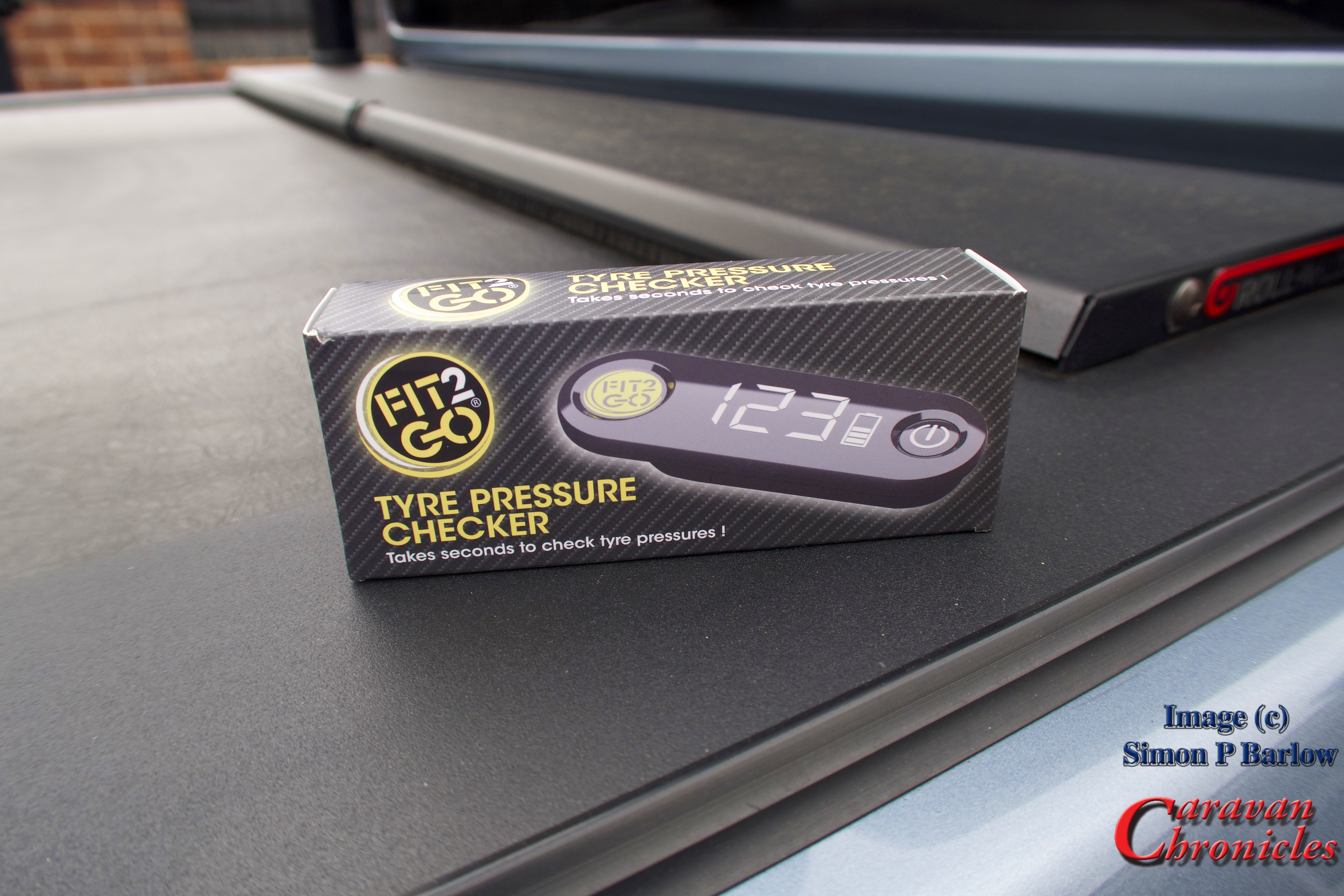
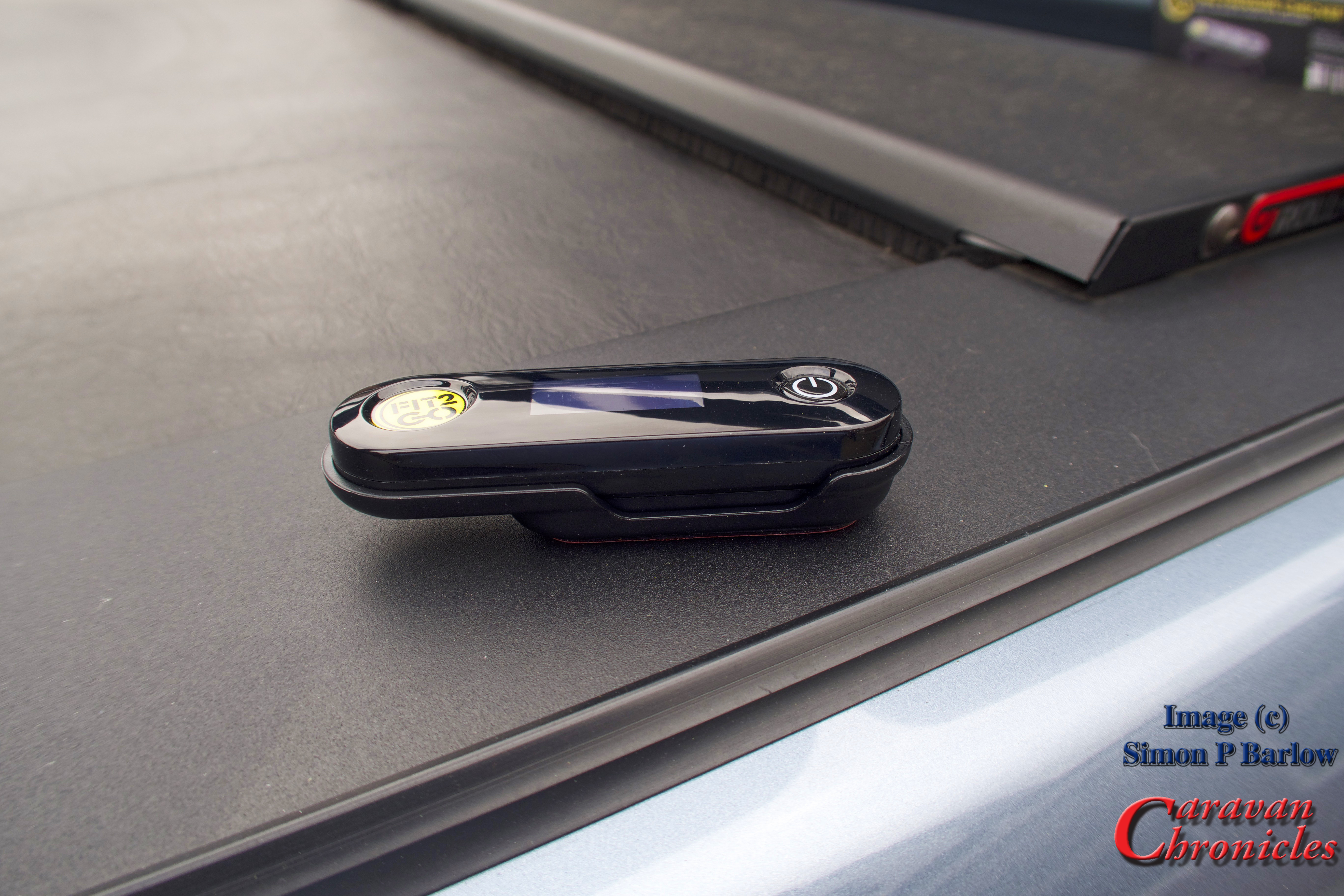
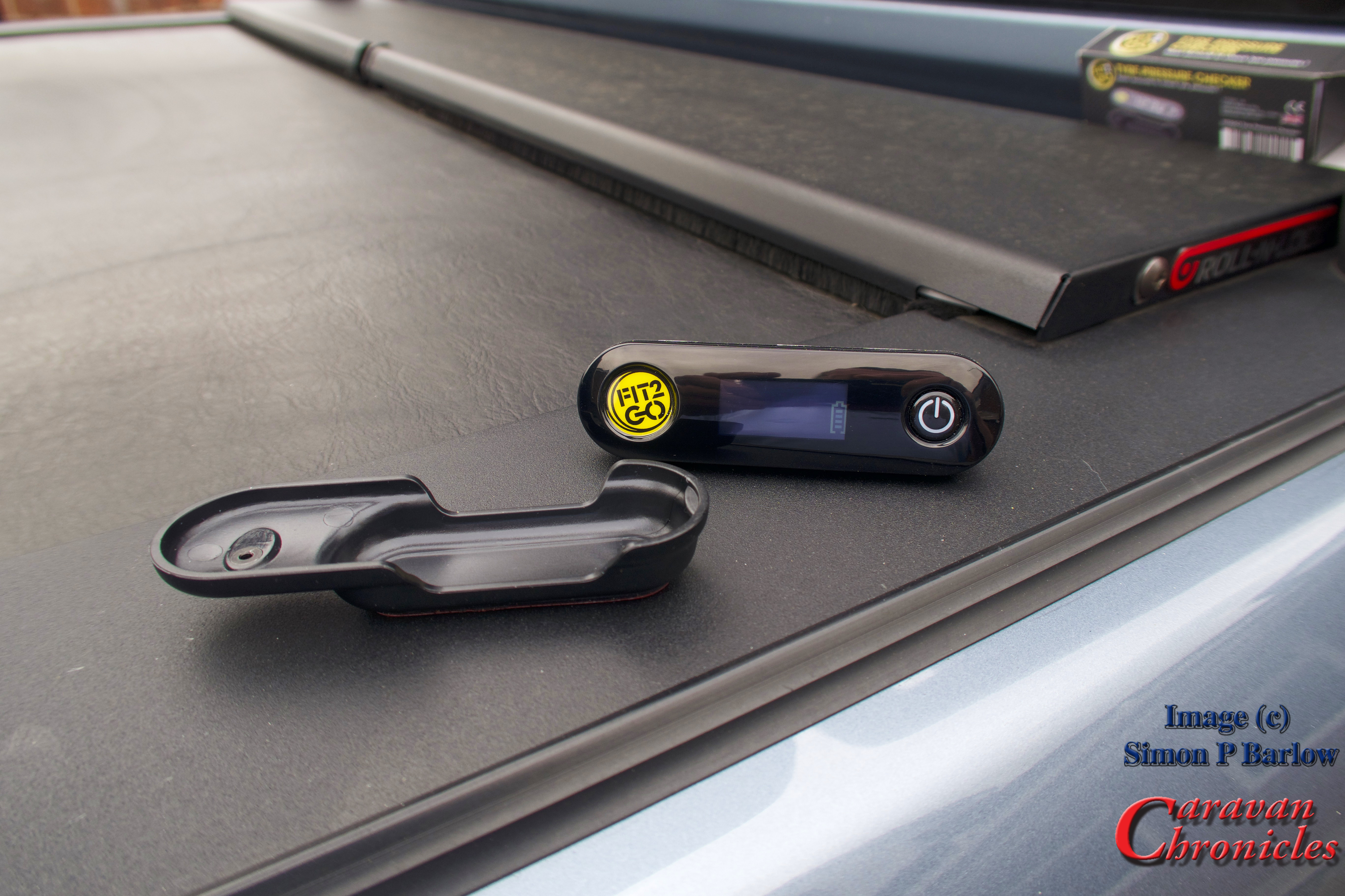
Operation is really simple. Press and hold the on button for five seconds and the unit will power up and display the status of the units own batteries.

IMG_1116

To obtain a pressure reading, simply place the unit’s logo over the tyre pressure sensor and you will feel a slight pull as the internal magnet pulls it towards the sensor, it’s this magnet that ‘wakes up’ the sensor.

IMG_1118

29 PSI is correct for the Amarok running light, and this sensor is showing 3 battery bars.

After a few seconds the Pressure Checker will beep and you can read the pressure for that wheel… and cleverly, you can also check on the battery level in the sensor. The display is in good old PSI, however if you don’t work in PSI and much prefer BAR, while the Pressure Checker is turned on, simply press the on/off button five times in quick succession and it will beep and the reading will now be in BAR. To change it back, simply do the same again to revert to PSI. To turn the Pressure Checker off, simply hold down the power button for 3 seconds and it will beep and turn off.

That is about as complicated as it gets.. really. The only real challenge is to find a spot to stick the holder!

IMG_1115
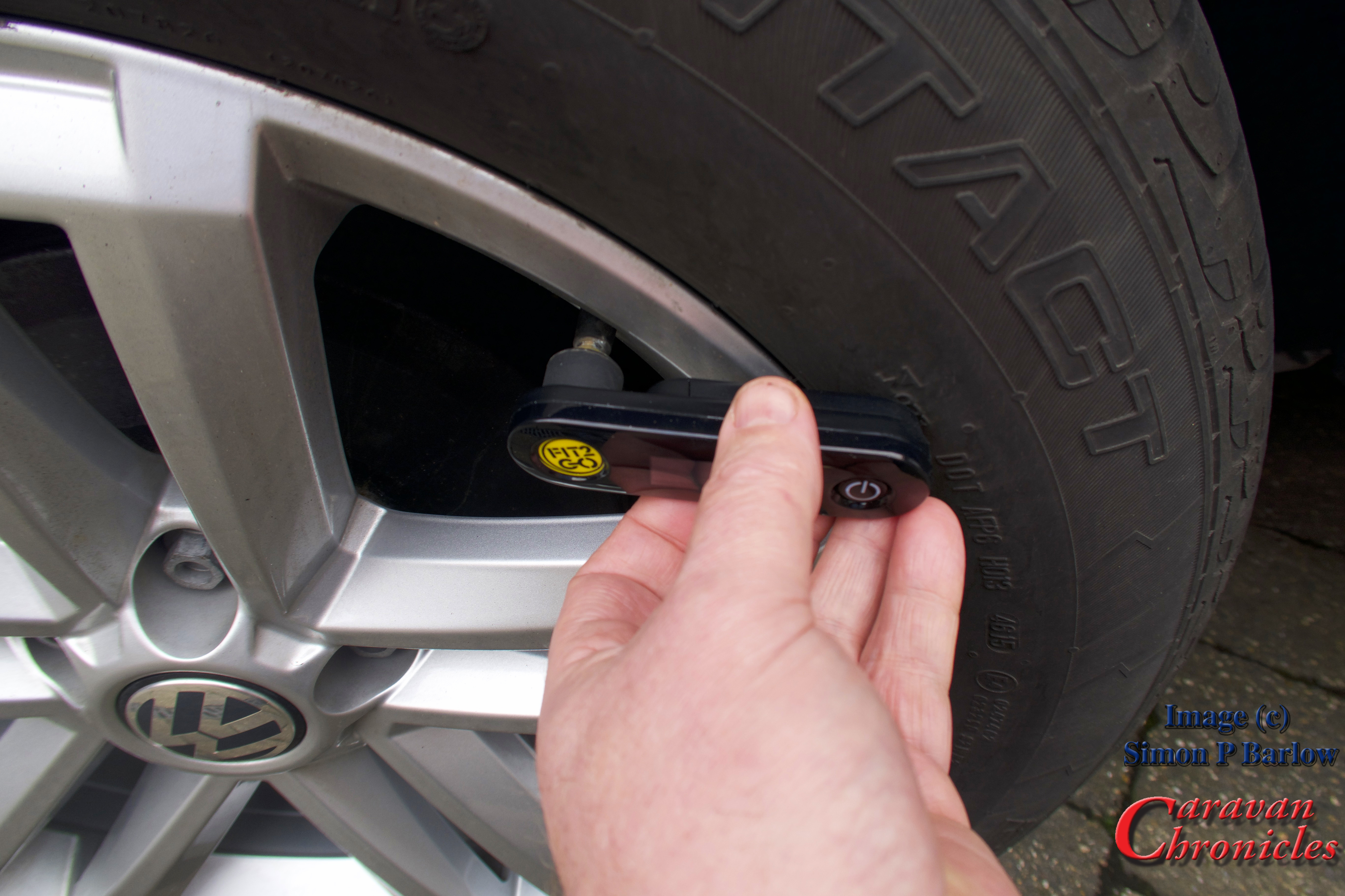
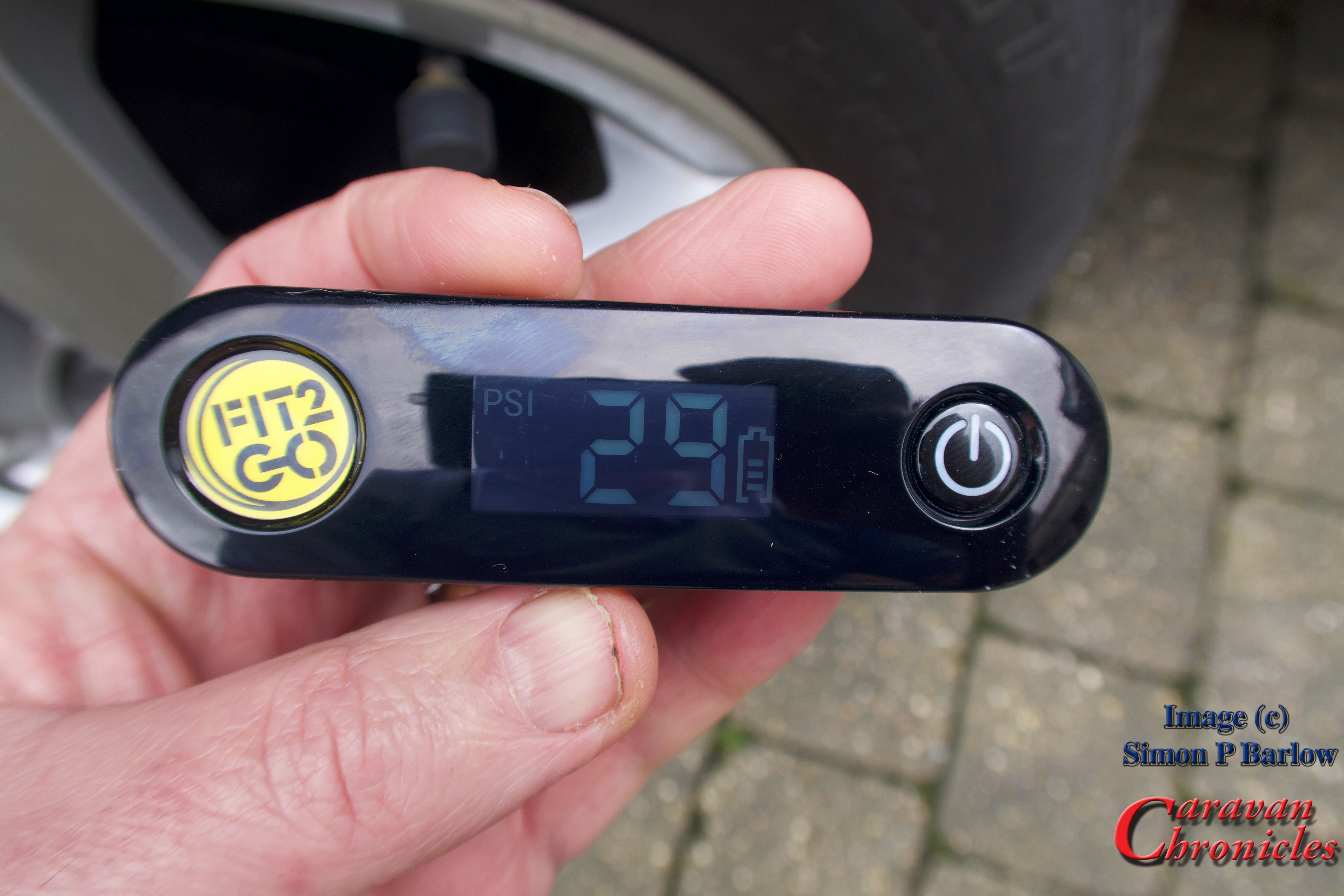
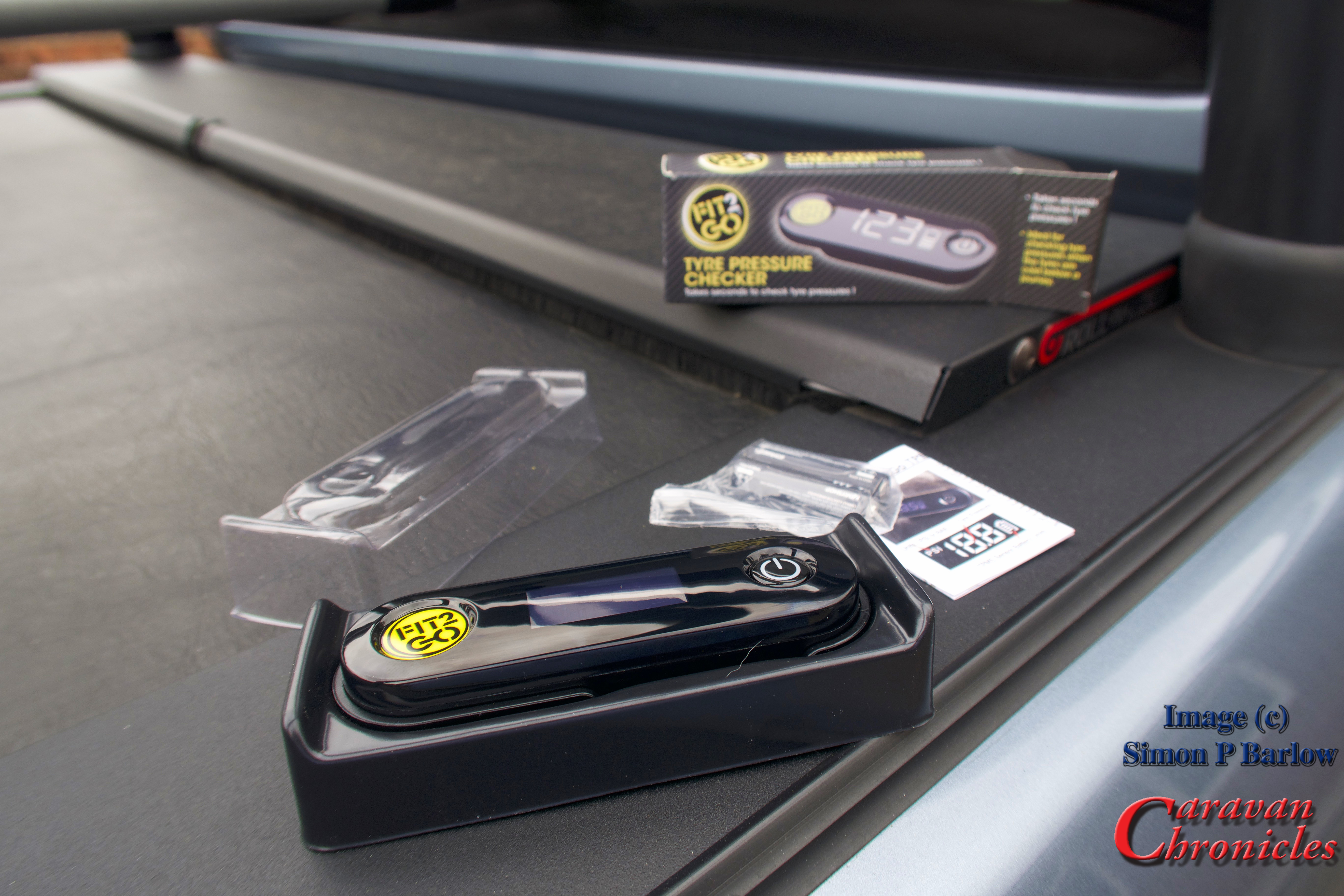
I have tried a few different TPMS ‘solutions’ over the past couple of years and all have plus points and minus points. As I am one of these people who likes to do walk rounds before setting off (throw back to my flying days I guess) I really didn’t want Formula 1 type information thrown at me all the time. I wanted a simple warning system and a simple way to check the pressure without having to remove any sensors. Fit2Go ticks these boxes.

If I did have a negative point about the Fit2Go system it would be the fact that the batteries in the sensors are not user replaceable. At least I do have a way to check the status of them now. The sensors are not too expensive when they need replacing, but  will be more expensive that replacing just a battery. Part of my brain is shouting “recycling” at me… and I do wonder why the manufacturer hasn’t come up with a recycling scheme… exchange your old sensors for new for a few pounds less than buying new and we will recycle them. Or maybe a discount voucher scheme when you recycle?

The Fit2Go Tyre Pressure Checker is available from RoadPro for just under £40 (exc shipping) or you can always find it on Amazon.

Fitting A Bike Rack to the VW Amarok – Finale…

Tags

, , , ,

It’s time to wrap up the bike rack install. I had to wait a few days for the final rack to arrive. Although I had ordered a twin pack of the Thule FreeRide 532 from Holdcrofts via Amazon and they had shipped out a twin pack, it would seem that their courier had ‘lost’ one and to Holdcrofts credit as soon as I emailed them they dispatched another… which the courier took four days to deliver.

IMG_1098 Continue reading

Fitting A Bike Rack to the VW Amarok – Part 2…

Tags

, , , , ,

OK, so now to fit the actual bike carriers onto the rack I had previously installed a couple of days ago.

We had opted for the Thule FreeRide 532 over the ProRide version. What put me off the ProRide were a couple of videos on YouTube showing just how easy it was to remove a bike supposedly locked on to the rack. The FreeRide 532 has two arms supporting the bike and offered an option for additional security…. which I’m not going to go into for obvious reasons!

I had ordered a twin pack of the FreeRide 532, unfortunately I only received one. It seems the other was lost in transit somewhere according to my enquiries with the supplier. The other thing I found out was they (or it) didn’t come with the “T” track fixings. OK so a quick trip down to my nearest Thule dealer Northwest Towbars to pick up the elusive fixings. They would remain elusive… Northwest Towbars didn’t have any in stock. Not to be out manoeuvred I’d make my own.

To the bat cave again…

I just happened to have some 2mm aircraft grade aluminium handy and cut eight 21mm x 45mm pieces. The FreeRide 532 normally has three mounting locations, but as there was an additional hole that lined up with the “T” track it would be rude not to use it! So I made four for each rack.

img_1069For the threaded bolt I had some dome head bolts handy. The width of the dome head was wide enough so it would not pull through the slot on its own so I was not relying on a 2mm think aluminium plate entirly. To hold the bolts in place I drilled a slightly undersized hole in the aluminium…

img_1074

img_1075img_1077…and used my small press to force the square shoulders of the bolt through the aluminium plate to hold it in place.

img_1078The result was eight “T” track bolts. A quick dressing up on the sanding belt and fine grinding wheel to remove any rough edges finished them off.

img_1079 The excess length of the bolt would be trimmed later.

Fitting the FreeRide 532 Racks

Sliding four of the newly made “T” track bolts in to the WingBars I could place the FreeRide 532 on to the bars.

img_1080I used a couple of nuts to hold the rack in place while I test fitted one of the bikes. It was a bit too tight. The swing up frame section that clamps on to the bike only partially engaged on the bike frame. The whole rack needed moving rearwards by about 10 to 15 mm.

Not a problem, as the WingBar mounting is off set laterally compared to the “T” track, reversing the bar so it faced the other way would solve this and effectively move the “T” track slot rearwards by about 20mm.img_1081

With the WingBar mounted in the other direction the bike was a perfect fit. Also it made it easier opening the end caps of the WingBar as configured the correct way round they were a bit tight against the roll bar.img_1083img_1084img_1082The next thing to address was the overhang. I still had around 50 to 60 mm of adjustment I could make to the rails of the FreeRide rack. Removing everything again and a bit of ‘adjusticating’ with a small rubber mallet soon saw the rails in the correct position. I had not been able to get the rear of the mount flush with the pickup tailgate as was my original hope, but checking with a plumb bob…

img_1090img_1091… It was still shorter than the tow ball and only about 40mm longer than the rear bumper. So the overhang wasn’t anything to worry about.  Even with a bike on the rack it would be clear of the caravan in the tightest of turns. Next it was just a matter of squaring things up and tightening everything down.

img_1092

I ended up locating the rack more to the side than I first planned. This was for two reasons. Firstly, once the second rack is in place it leaves me with nearly 800 mm between the two racks which will allow for the option in the the future of having the ability to install a mesh tray, ski rack, surfboard rack (we don’t ski or surf… ho hum) or slimline roof box if we ever run out of storage in the Amarok. The second reason is it will give the rear view dash cam a relatively unobscured view rearward even with two bikes on the back.

Everything torqued to the correct settings, I topped off the nuts with an additional nylon lock nut to make sure they could not vibrate loose…

img_1093img_1094… and using a Dremmel I cut off the excess thread and ground off any sharp edges.  I need to find a suitable plastic or rubber push on cover for these then I can give them a quick coat of preserving grease.

One thing that I did think about was the prospect of the swing arms bouncing up and down when bikes were not on the rack. A quick rummage in my straps box produced a few of these little blue straps and a handy slot on the mounting plate seemed ideal…

img_1096… problem solved. A simple solution to something that may or may not be a problem.

So one rack fitted, all that is left is to repeat for the other side, when it arrives!

img_1097

Fitting A Bike Rack to the VW Amarok – Part 1…

Tags

, , , ,

It’s been a few months since we bought our VW Amarok and I hadn’t originally intended it to take this long to install a bike rack or carrier. What slowed us down was sorting out the bits needed for mounting a bike carrier above the bed of the Amarok. In the USA, pickups are plentiful and there are various companies that make carrier systems and mounts for pickups. My initial thoughts it would be fairly easy and started perusing the Thule website. Unfortunately they did not sell the correct mounting hardware for where I wanted to mount the rack.. on the side rails for the Roll-N-Lock cover.

Searching the internet found plenty of results for the type of mounting I wanted… all in America and the most promising system was produced by Yakimar.

However, trying to find a retailer that would ship to the UK was a bit of a problem as most would only ship to the US and Canada. I did eventually find a company in California that would. The next hurdle was the cost. To buy everything and get it shipped over here would ring up a massive £2180 bill at the checkout. This was not worth it. I out the bike rack on the back burner for a while… and the pound against the dollar slipped in the meantime.

Getting ready for installing the bike rack

I started looking around again at the start of this year and returned to Thule and Fiamma. Could I make up my own “kit of parts” to do the job? Fiamma while having a great selection of racks and bits didn’t provide anything in the way of a roof bar so back to Thule again. While mooching about their website I accidentally got on to the American  area of their site and while looking for mounting feet came across one specifically designed for mounting on to flat roofs. The part was intended for a Fibreglass canopy on a Jeep Wrangler but pictures showed them being used on a number of vehicles and camping trailers. This was exactly the part I needed.

I checked with a number of Thule retailers to see if they had Kit 3113 which was used to mount Rapid Podium Foot Pack 460R on flat surfaces. No one had it, so a quick email to Thule asking if it was obtainable in the UK or Europe was fired off. The answer was a bit surprising. It was an American part produced by the American Division and was not obtainable in Europe.

OK, back to my contact at Worldwide Cyclery in California… did they stock it and could they ship it? It arrived within six days. I also ordered the Foot Pack 460R as it was over £60 cheaper even after paying import duty than buying it in the UK on-line. I now had the means to mount the WingBars(Aeroblade). I just needed to check the size and order these and two FreeRide 232 bike mounts. Before I ordered, I checked the width I’d need. Next problem, The WingBars in the UK were 1500mm wide and in the US being manufactured in English sizes were slightly wider by about an inch. They arrived a few days later from the US!

OK, so now I had all the parts… to the bat cave!

Assembling the 3113 mounting plates

Assembling the 3113 mounting plates

The first task was to assemble everything so I could to a test fit of the whole caboodle on the back of the Amarok before drilling anything… always a good idea! The four Kit 3113’s were assembled first and the four 406R feet were mounted on to them.

img_1048

Assembling the 460R on to one of the 3113 mounting plates.

img_1045

 Once this was done, the sub assemblies were slid on to the ends of the WingBars.

img_1050

Once this was done, I could roughly position the two partially completed WingBars across the bed of the Amarok.

img_1051

I now needed to check the position of the bike on the FreeRide 532 so that would in turn give me the position I needed to mount the WingBars. From the centre line of the mounting plate the front edge of the front wheel is about 550 mm, so the front WingBar needs to be at least 550mm back from the rear of the cab.

img_1044

However, the Amarok’s sport bars have to be taken into consideration as these stop the front wheel of the bike going too far forward and will help protect the cab.

img_1067

This presented a problem. The rear of the FreeRide232 protruded back and hung over the rear tailgate by about 350mm and if possible I wanted everything flush. Not a problem, the two bike wheel mounts can be slid forward and backwards to accommodate various size bike frames and the main mounting point… with a little assistance from a rubber mallet and be slid backwards. So in effect I nudged the two main bars forward so they didn’t protrude over the tailgate and the bike still fitted. You can see my mark as I started to move the main mounting plate on the picture below:

img_1053

While doing the test fitting and adjusting the position of the mountings, I discovered I had a bit of luck. On the Amarok sport bar there are two ABS plastic mouldings that fit round the bars that are designed for mounting spot lights or work lights that just happen to line up and can be used as ‘rub strips’ to stop the front wheels contacting the coated stainless steel sports bars.

img_1065

I could now measure where I wanted the WingBars to be located and marked out the positions. I wanted the rear cross-bar to be as far to the rear as possible (something planned for the future) and worked out the distance from the front bar which had to be located so the bike rack fitted with the front wheel tucked against the roll bar.

img_1054

As the sides of the Roll-N-Lock cover had a slot underneath, I’d previously machined 4 pieces of steel to fit in them and pre drilled and tapped the holes. All I needed to do was drill the sides of the Roll-N-Lock cover.

img_1057

The (supplied) hex bolts passed through and screwed into the steel plates I’d machined. I also added a spreader nut and lock nut underneath… just to be sure! The lock nut wasn’t tightened up to the spreader nut, so if someone tries to undo the hex bolts, they will simply back off a little then spin round.

OK, first one done time to do the other side…

img_1056

Other side complete a quick test fit of the WingBar…

img_1059

While pre-positioning the front bar ready for marking out, I was interrupted by Sue… a welcome coffee and hot pie break!

img_1062

Both rails fitted, it was time to add the covers and rubber strips…

img_1051

A final position check of one of the racks and time to call it a day as the rain set in again.

img_1063

The spacing of the bars will give us lots of options for the future to add a top box, ski mounts – these will allow ski’s to be carried angled upwards over the cab (have to learn to ski first though!) or a mesh tray.

I’ll post part two soon showing the bike carrier mounting and go into some of the little pitfalls I have come across.