Tags
Caravan Cleaning, Caravanning, diy, Electrical, Maintenance, Modifications, rv, Trailer Lights, Water Pump
OK we are still working on a few bits and pieces but the weather on Friday and Saturday was ideal for cleaning the outside of the 5th Wheel. So while Sue made a start on the cleaning of the nose cap, I finished the first stage of the water pump relocation project and upgraded the wiring.
At some point the original wiring had been modified to include a 10 Amp socket in the wet bay to allow the use of an external pump to fill the fresh water tank. We still wanted to use this as the original external electrical connector was missing the original plug and it was just easier to sort out the wiring. It had been modified using 6 amp rated cable to both eh internal water pump AND the 10 socket. All fused on a single 10 Amp fuse. The wiring I upgraded to 16 amp rated cable but retained the 10 Amp fuse. So there should be no issues with cable rating in the future.

You can see from the photo above some of the work involved in moving the water pump. It was originally mounted where the holes are on the vertical wall. This resonated quite badly as it is located just under the bathroom and was particularly loud at night if the loo was flushed.
So to reduce the vibration from the pump before mounting it in a different location I made a aluminium cradle to mount the pump to and sat this on rubber isolation mounts before mounting it to the floor using stainless steel bolts, washes and lock nuts….. in fact I used stainless hardware for all the mods.
The next job was to install a 0.75 L SeaFlo accumulator with the bag set to 15psi and isolate this from water knock caused by the pump using a stainless jacket flexible hose in a loop. I have another stainless hose that will be used in a future upgrade that will allow this pump to be used to draw water from a 120 litre bladder in the back of the pickup truck….. but for now that’s going to be a end of season upgrade.
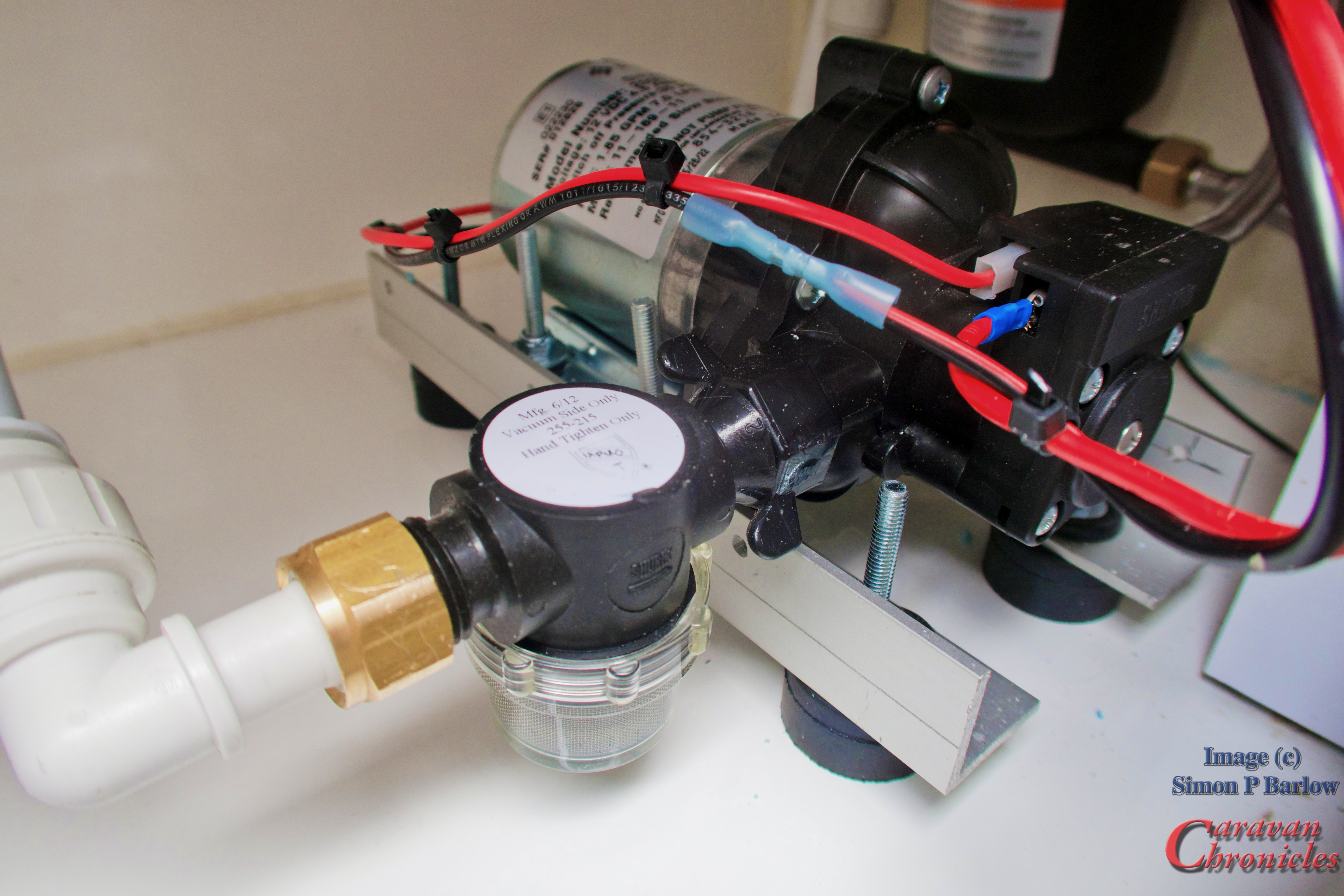
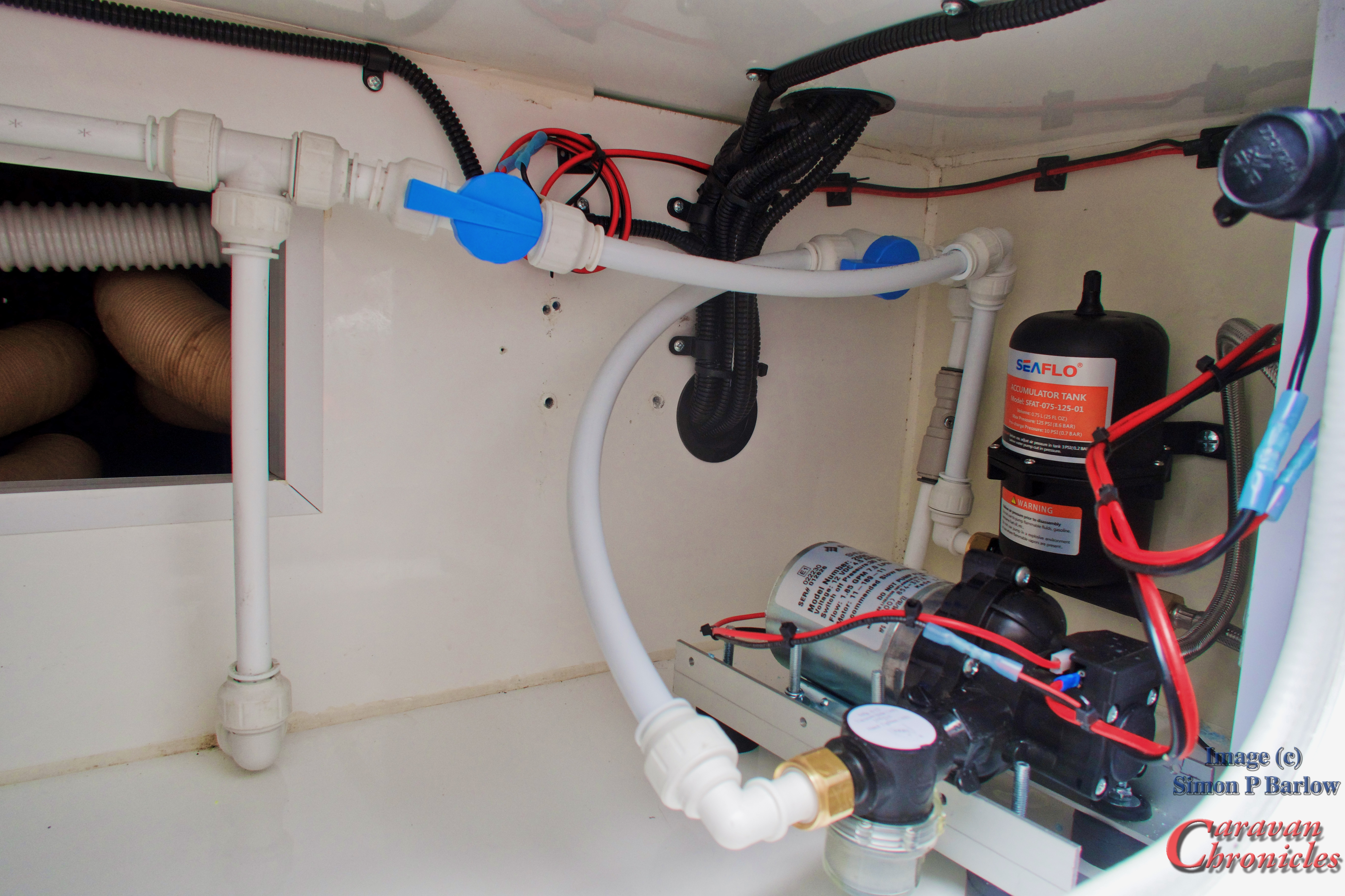
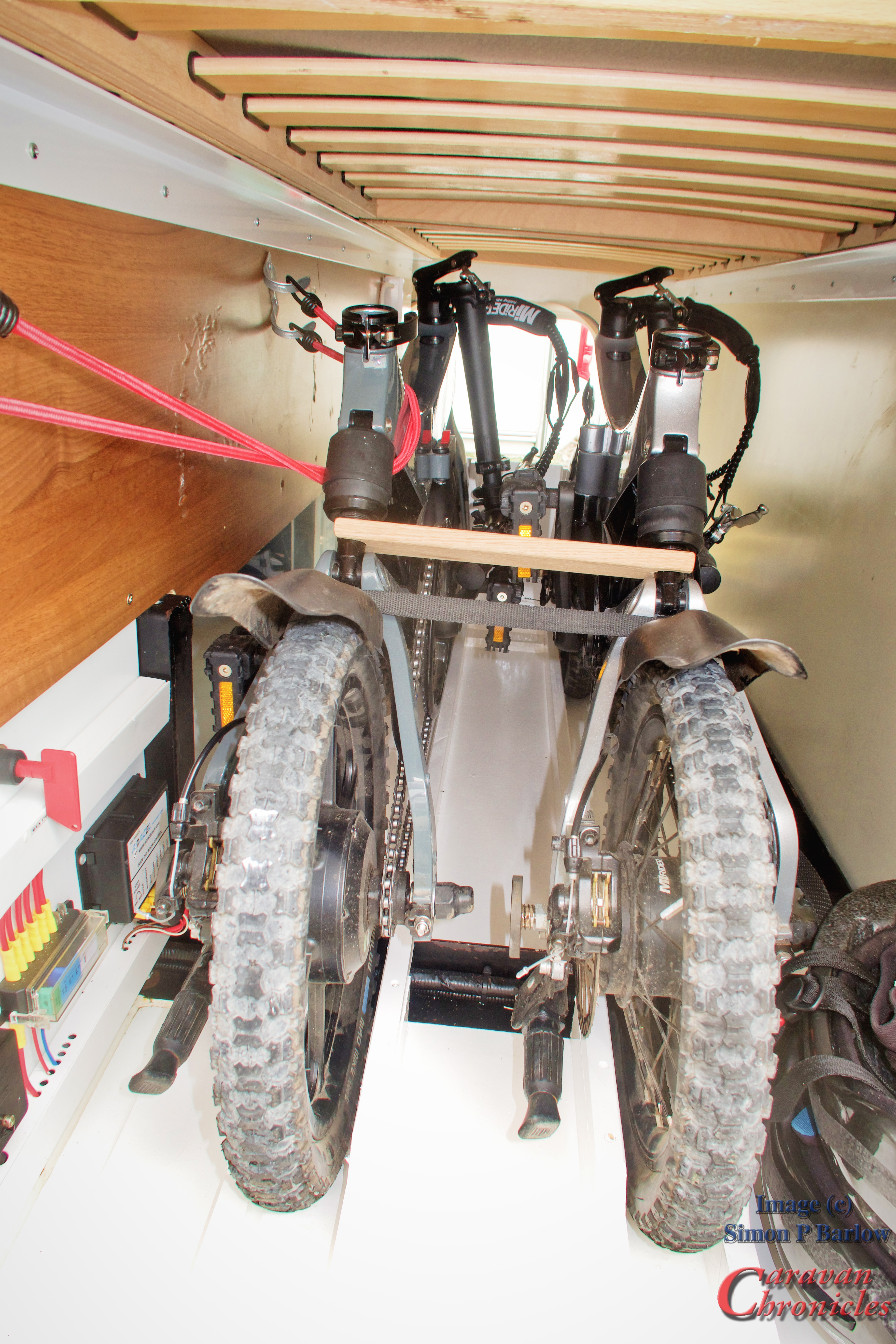
The two valves [in blue] are used to isolate the feed from the water tank and the output from the pump and are a bit untidy…. these will be repositioned shortly as I’m going to add an outlet to allow me to connect a hose so I can wash off the bikes and flush the grey water drain pipe when I disconnect after dumping on a serviced pitch. I’ll also swing the pump filter 90 degrees for a bit of space saving and I’m thing about a water treatment pre filter between the tank and pump. We have a filter on a separate clear water dispensing tap the we use for the kettle or food prep…. but this would allow all the taps to be protected.
The result of moving the pump, anti knock loop and accumulator is that now we cannot hear the water pump running in the caravan. Result!
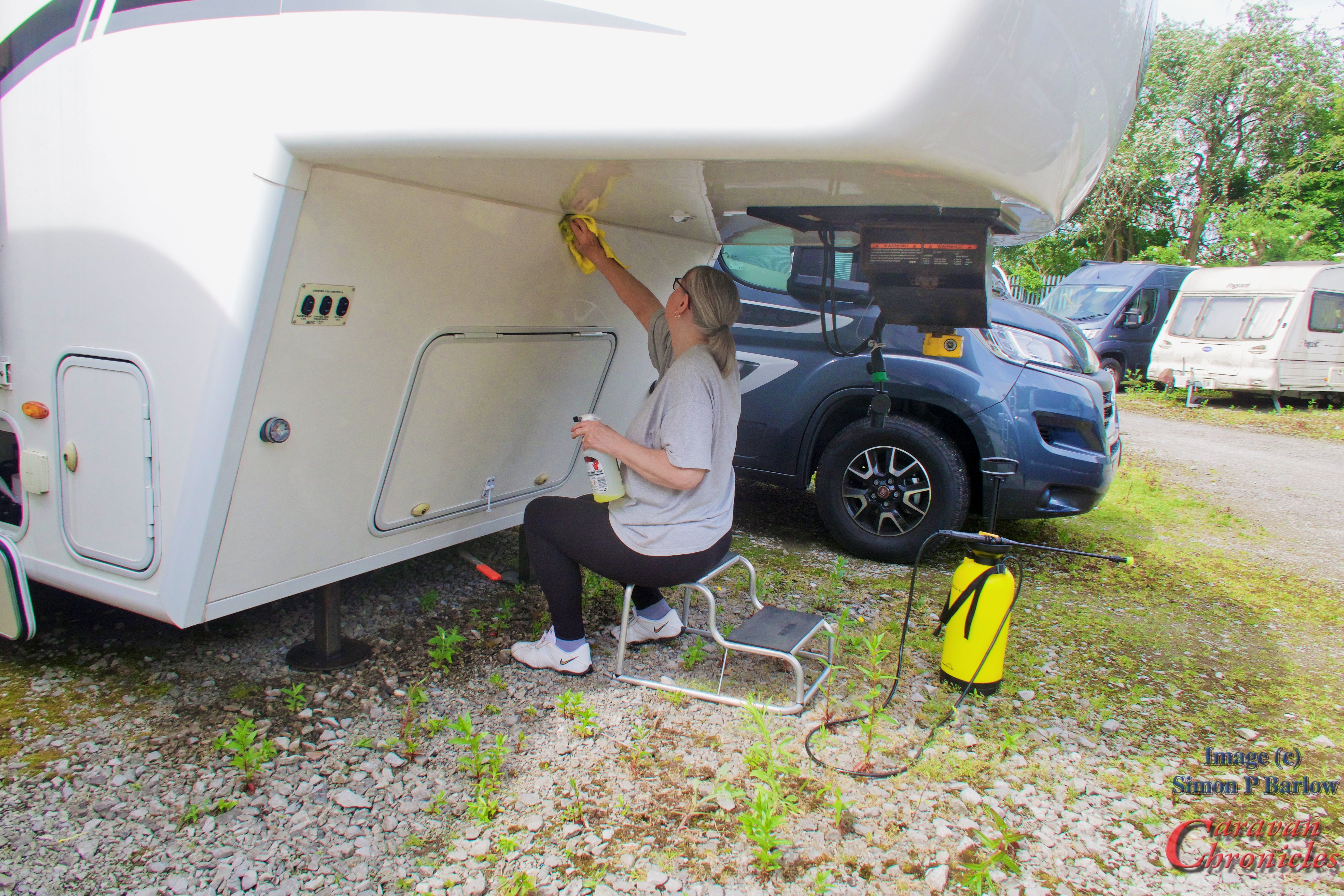
Sue working hard cleaning the front locker wall after going a grand job on the front cap above. The task of cleaning…. including the use of a tooth brush around all the door seals eventually took two whole days.
If anyone has tips about restoring the plastic handles on the lockers I’d be grateful if you could leave a comment. I’ve been steered to something called “The Pink Stuff” miracle cleaning paste by a couple of other 5th wheel owners
Let there be light…. more light in fact!
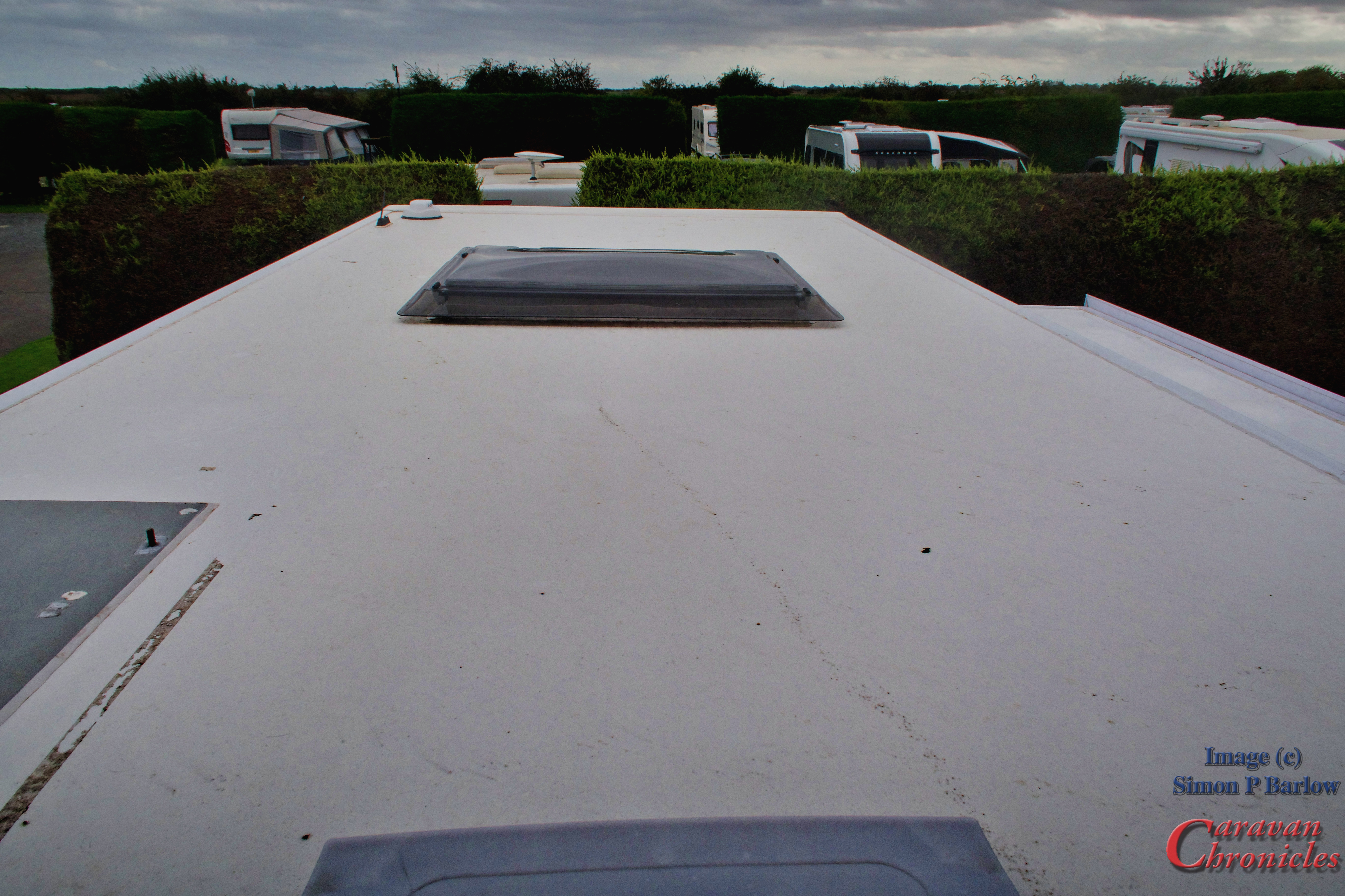
The other title upgrade was to the rear of the 5th Wheel. I have been reading up on some proposed lighting changes for articulated trailers in some countries. What used to be called front and rear marker lights seem to have gone through a name change….. these are now called “edge out lights”.
If you are parked in a straight line they are not required to be seen, but if you park at an angle exposing the edge of the trailer, the edge is required to be seen by either on coming traffic or following traffic… depending on the angle you are parked at. I’m not exactly sure how this affects things in general in the UK, but it was interesting that I picked up on the watching a couple of training videos about hitching and unhitching a articulated trailer in preparation for your HGV test.
As I understand it, if you are stopped and an edge of the trailer is exposed past the normal line of the prime mover unit and trailer straight line width then this edge must be marked with lights.
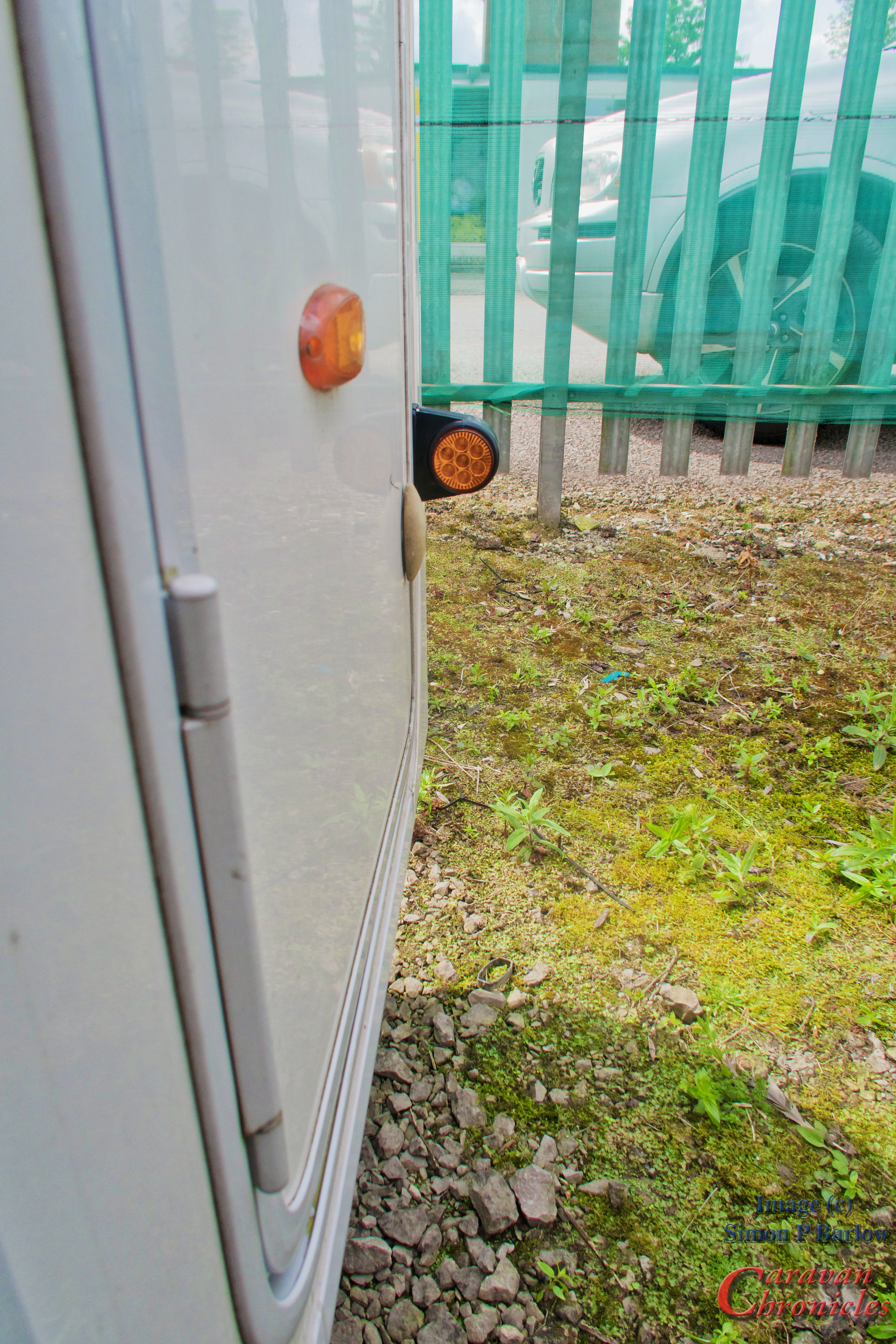
From the front our ‘marker lights’ seemed to be located in the correct position…. but I could not find out about the rear in much detail, so a quick chat with a man that knows all about this he pointed me in the right direction. Although that said he was also unclear as how this would affect 5th wheel caravans as he thought it might only apply to commercial vehicles. I did mention that the VW Amarok as most of the heavier pickups are actually listed and taxed as commercial vehicles. That brought some “Hmmm’s and Ahhh’s” into the conversation….. including “in that case you will need the ‘angles of death’ stickers in Europe….. Angles Morts”
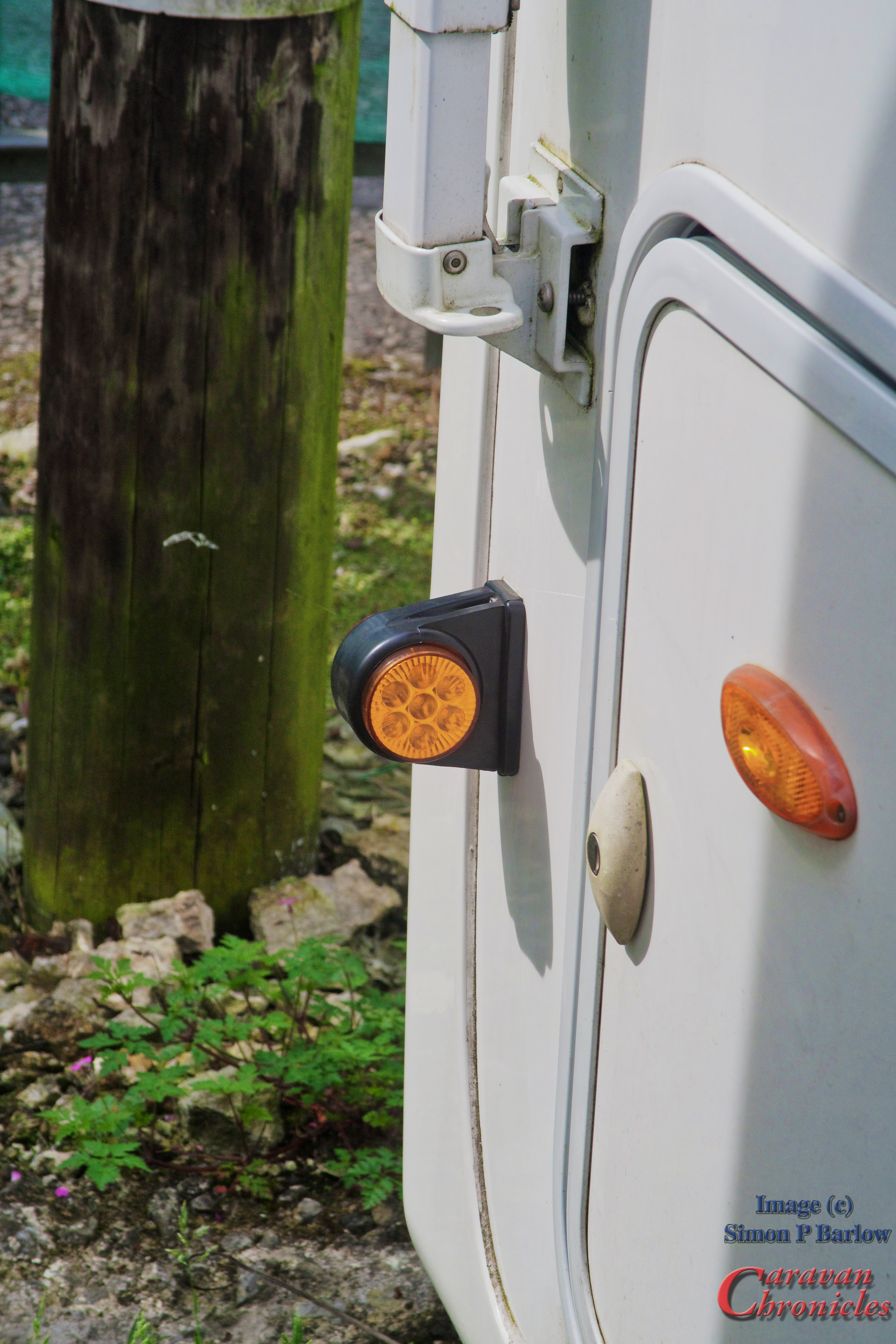
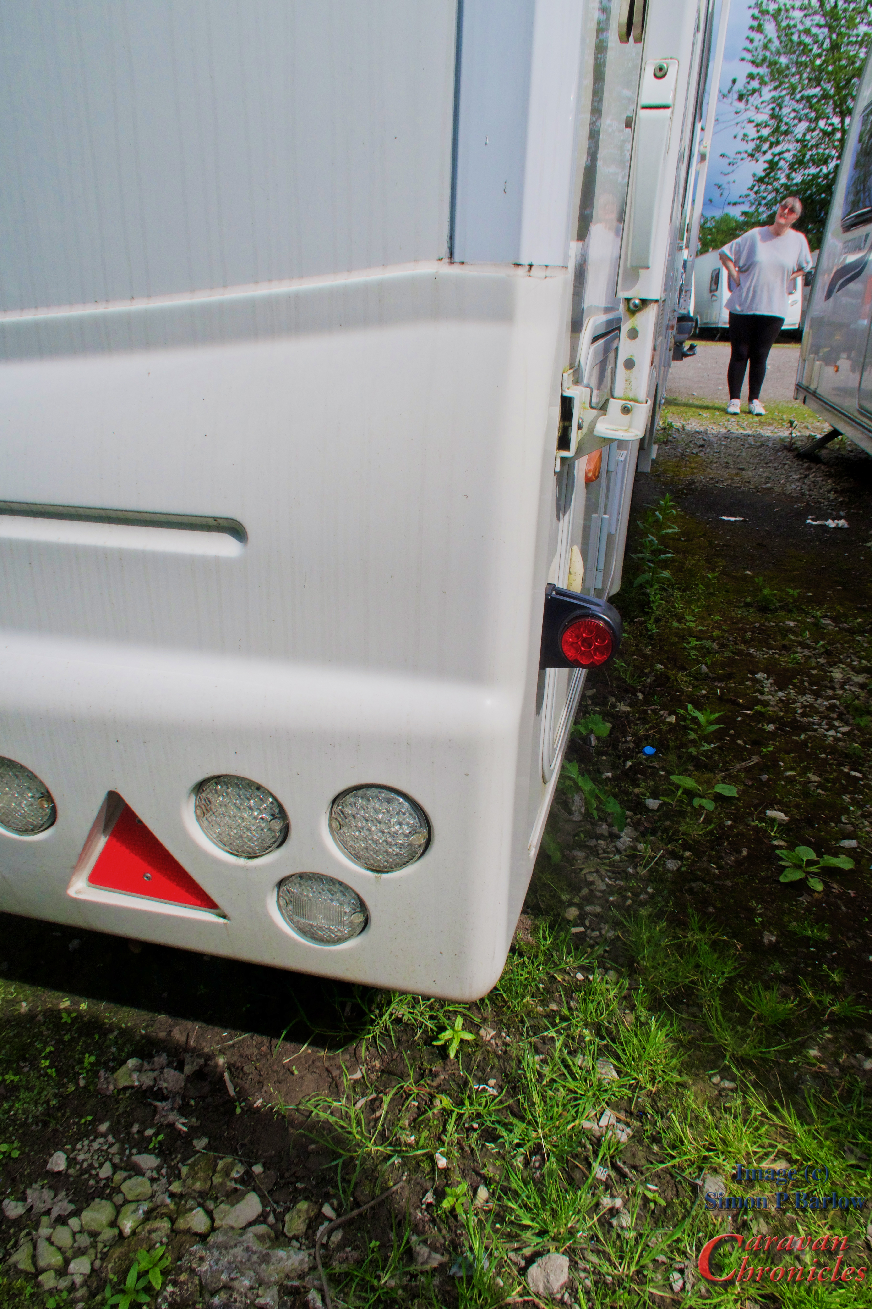
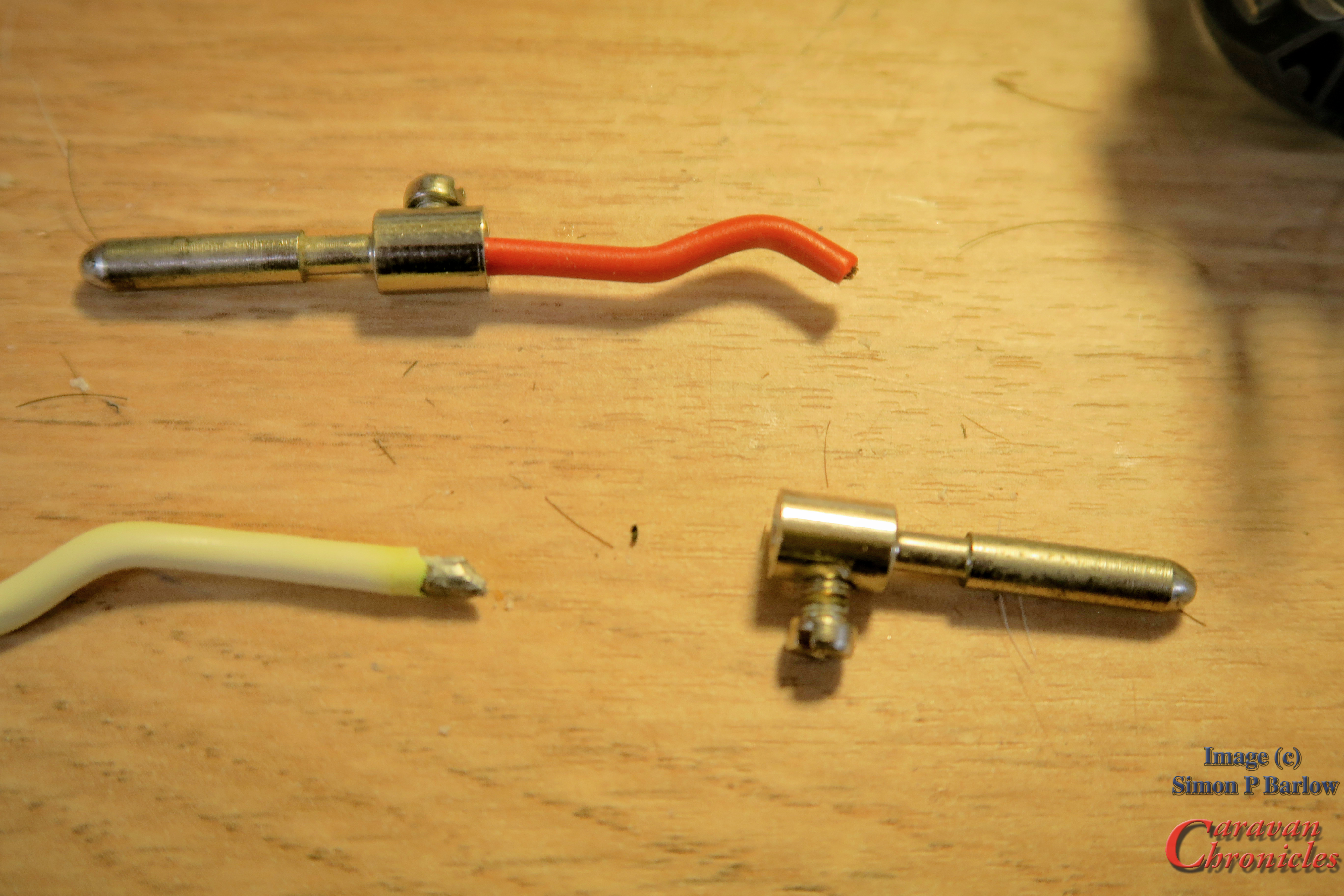
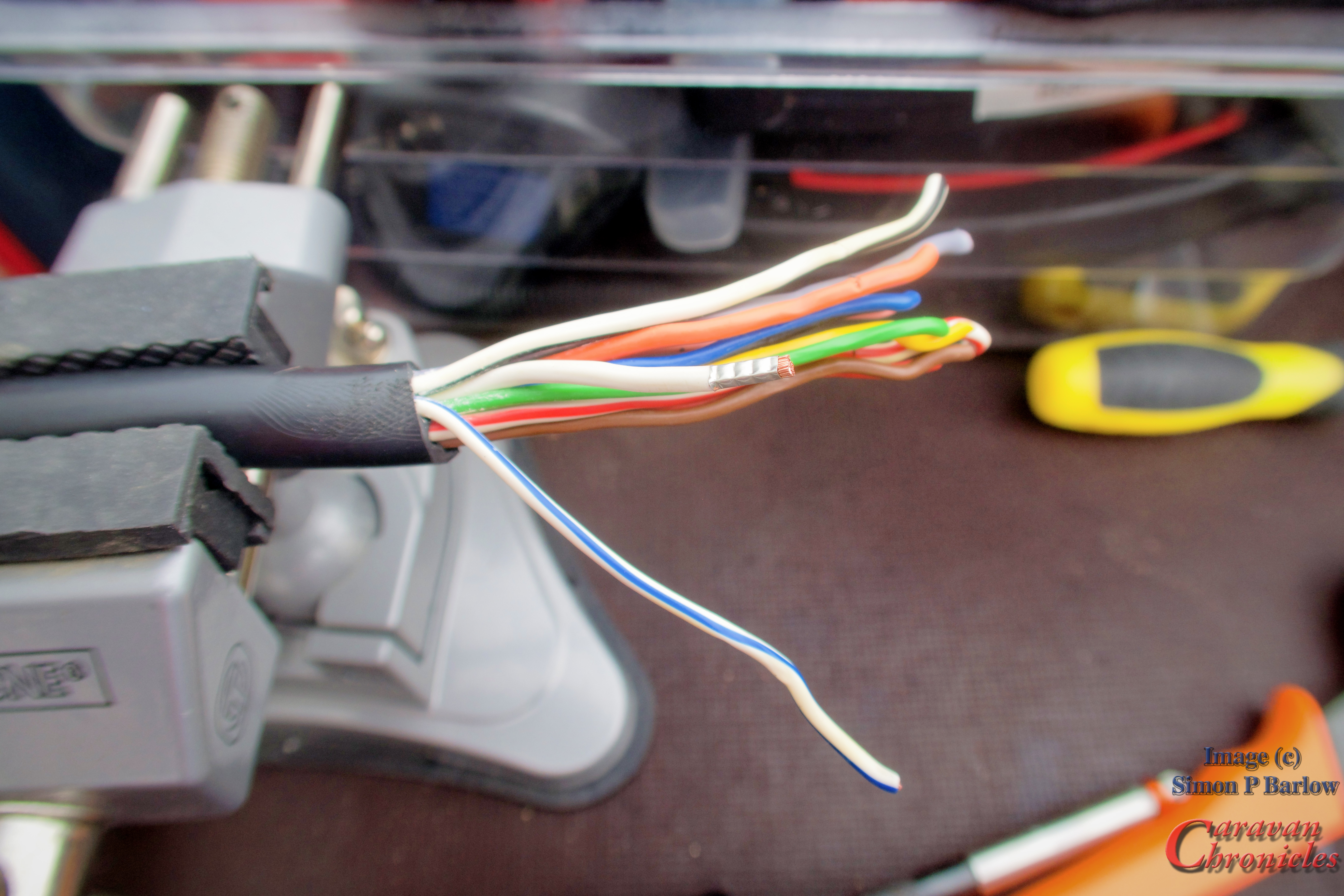
These lights show red to the rear and orange to the front. As they are located at the widest part of the trailer…. on this side that has to include the awning frame they indicate the edge of the trailer to the rear…. and from the front the amber side also indicated the edge of the trailer to oncoming traffic.
A really handy thing for me is when driving even during the day I have my side lights on. The amber light I can see in my side mirrors and it clearly marks the end of the trailer…. in inclement weather this has become a bit of a game changer as I now can clearly see even in a lot of road spray where the back of the trailer is.
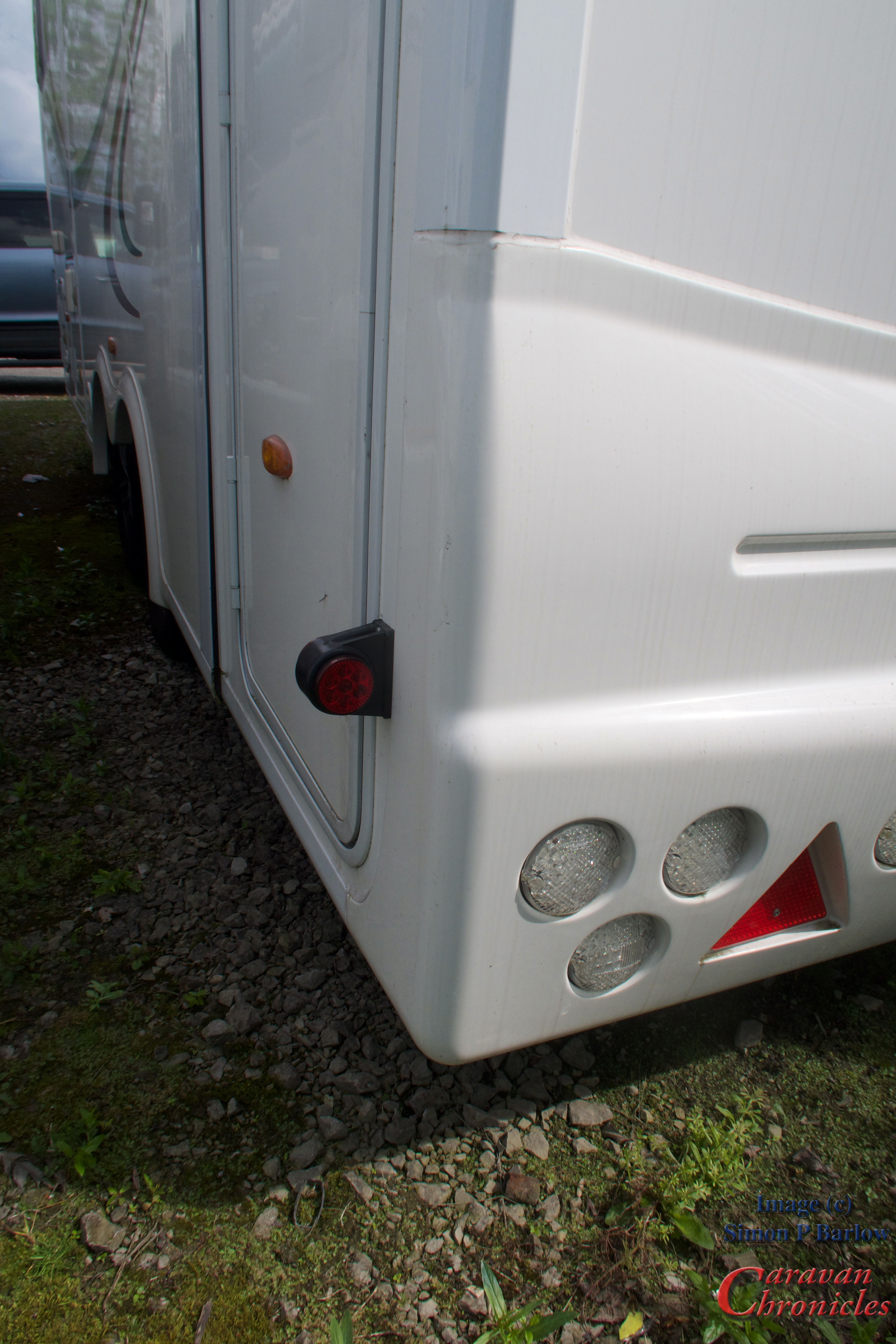
when following lorries I always notice how bright these tiny LED rear lights on rubber stalks are that stick out from the side of the trailer…. I tend to notice these before I sometimes see the rear light cluster….. these are the same… they are CE marked along with the UK / Euro markings so must be compliant with regs but they are brighter that the 5th wheels rear red side lights….. and the more rear lights I have hopefully will reduce the chance of someone getting to intimate with the rear of the trailer!
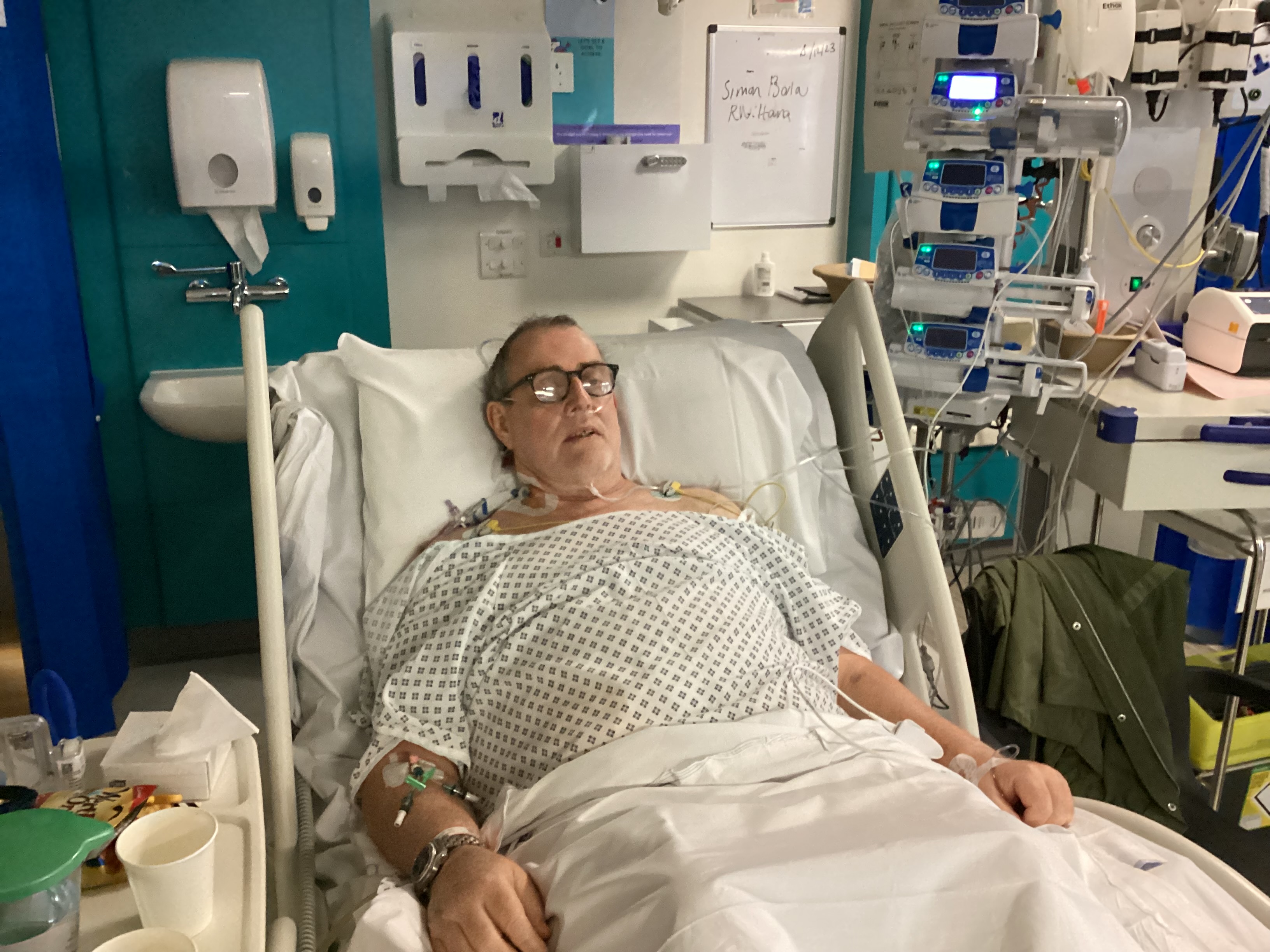
Personal note….
Thanks to everyone asking how I’m progressing….. the chemo is going well and I seem to be quite lucky as I have very few side effects to the point that really the couple I have is a mild inconvenience.
I have settled down in to a routine of having a stoma and bag…. bit of a shock to me when I had it done as it wasn’t mentioned in the pre-op that this might be an outcome….. but there again it might have been…. I was on that much medication I was convinced that I’d had a conversation for about an hour with a man stood at the end of my bed dressed in 1040’s clothes complete with trilby hat and chain smoking staring up the ward never taking his eyes of someone I could not see because of the curtains around my bed. He told me he was tasked with keeping an eye on this person as he was suspected as being a spy for the Germans.
What the hell were they medicating me with!!