I seem to have had an increase over the last few weeks of emails from people involved in building, modifying or upgrading Overland Expedition type vehicles. I think some of my posts must have been quoted or referenced in related forums. A lot of questions are related to roughly the same group of topics so I thought I’d produce three drawings to help answer the bulk of the questions. If you read down the comments on some posts I have answered a lot of specifics that might help. I’ve merged a lot of the questions into a paraphrased ones…
Question 1
“How can I get my LED light bar and spotlights to come on when I use my main beam switch but I want to disable them when on the highway?”
The questions were from a number of 4 x 4 Off Road enthusiasts and Overland vehicle people. Simplest way I could come up with was using a couple of diodes (details on the drawing) Three switches… one for LED Light Bar, One for Driving Lights and one that allows you to sync the LED Light Bar and Driving Lights to the operation of the main beam in the vehicle. Flash the main beam and with the Sink Switch ON… all the lights will flash. Note… this may be illegal in some countries, so having the option to turn off the facility when on the roads ‘should’ keep you within the law…. don’t quote me on it!!!
Question 2
“Whats the best layout for connecting a solar controller / inverter / isolation switch to my battery bank?”
The best schematic I could come up with that is flexible for most situations. I’ve put a few notes on the drawing. The various components I’ve drawn generically…. all can be found at your preferred supplier.
Question 3
“What’s the basic layout of the vehicle fridge and leisure battery charing circuit?
This I think has come from a few on-line discussions relating to poor performance of the fridge and leisure battery charing in older 4 x 4 vehicles. I was receiving for a while a number of questions related to upgrading older installations. I also receive a number of emails asking how to add the facility of fridge and leisure battery charging to older vehicles and upgrade the 7 pin tow socket or old military lights socket.
You can download the PDF’s and are free to use for personal use. If you post them on other forums I’d appreciate a link back to this page and/or an acknowledgement.
I’d appreciate any feed back in the comments below.
A few weeks ago I posted a blog post called “A Quick Fault Finding Tip…” and that generated quite a few emails regarding electrical testing and how to trace faults. In fact a lot of the other electrical posts I’ve done over the years still generate emails and comments (it’s always worth checkingback on some of th eolder posts to read the comments) I’m going to try to explain a technique that’s really handy to have in your tool box for general fault-finding.
Earth Side Testing
Most people who perform general maintenance on their vehicle, motor home or caravan will be familiar with checking the voltage of the vehicle or leisure battery using a multimeter. Great little things to have and personally I think everyone should be able to do the basics with one. So as a bit of a refresher I’ll go through this scenario with you. Checking the lights on your tow vehicle you notice one of the brake lights is a lot dimmer than the other. Let’s find out why. I’m going to simplify the circuit a bit it should give you the idea behind the principle.
Depending on the device you re reading this on the drawings might be small. If you want to see the drawing full size just click on it to open it up full size.
In the drawing above you can see the basic circuit. The positive lead from the battery goes through the ignition switch and on to a fuse. From there through a connector to the brake pedal switch and on to another wiring loom connector to the back of the vehicle. It passes through another connector before arriving at the brake bulb holder. The holder is connected to the vehicle chassis via another wiring loom connector. The vehicle chassis is connected back to the battery in the engine bay. You can see we’ve checked the battery voltage with out meter and it reads 12.68 volts… so not a flat battery. We’ll make a note of the battery voltage.
OK… so the problem is this bulb is not at full brightness.. so it’s got to be a loss of voltage supplying it somewhere in the circuit. We need to check the voltage along the circuit with the bulb lit (circuit live) and the black negative lead of our multimeter attached the battery negative terminal. (I’ll explain how to do this later).
Probably the next place to check it would be the fuse… 12.66 volts, not too bad only 0.02 or 20 mV loss… lets keep going….
..next is a wiring loom connector, back probing it gives a 10 Mv drop (loss) normally these modern connectors are pretty good.
Brake light switch… Hmm a bit more of a drop… maybe a quick spritz with contact cleaner will sort that…
Back probing the next connector gives a bit more of a loss… I’ll come back and check the brake light switch connector.
OK, now at the back of the vehicle and a bit more of a drop at that connector but nothing too much…
Well 12.13 volts on the bulb contact… so between the battery and bulb positive tip a total loss of 0.55 V or 550 mV…. that’s about within limits as I would not expect to see much more than a 500 mV… half a volt drop on a typical circuit like that. So what’s going on? A 500 mV drop can’t account for the dim bulb?
However, if we keep going and measure the voltage on the earth side of the bulb holder….
Hang on we see a reading of 2.67 volts. How can that be? We are connected to ground at both ends of the meters test leads? A circuit has two sides, the positive side to the load – in this case the bulb and the return or negative side back to the battery.
Just because the negative wire on the bulb holder is only short and goes to a bolt securing it and maybe many others to the chassis doesn’t mean we can assume it is the same as being clamped to the negative battery terminal.
A few things to ponder…. vehicles are made of steel… steel is not as good conductor of electricity as copper… nether is aluminium that some vehicles have in their construction. At one time steel panels were all spot welded together… now a lot are bonded on with specialist adhesives. The earth point may well be in the boot or under the floor and will be subject to corrosion as will the main battery neutral cable in the engine bay. All this can compromise an electrical path back to the battery.
If we look at the voltage drop on both sides of the circuit we have 0.55 volts on the supply added to 2.67 volts on the neutral side…. 3.22 volts in total, so we are trying to light our bulb with only 9.46 volts.
Could we have got there quicker?
One of the checks I always do first with the ignition on is the battery voltage check to get a reference to work with and then simply move my red positive test lead over to some main point on the engine block….
If I get a reading of more than 0.4 volts (400 mV) obviously my negative return path from the vehicle chassis is compromised. Time to turn everything off and undo the main earth cables to the chassis and engine and give them and the mounting points a good clean with scotch bright or fine emery and a dab of specialist grease (see “Shopping” below) to protect them from further corrosion.
In the scenario we have just gone through, I’ll bet a wet weekend in Blackpool that cleaning both the earth terminal at the back of the vehicle and the battery earth to the chassis would have sorted the problem. I’d also have a look at the brake pedal switch as there is a bit more of a voltage drop than I’d like. Most likely it’s the connector rather than the switch itself.
For those that tow…
Nearly all tow bar wiring looms will ground to the same point in the back of the vehicle with some of the other assorted vehicle earth cables…. installers take the easy route and if there are already cables earthed there … then another couple won’t make a difference.
This can and will have an effect on the performance of your caravan electrics. Both the leisure battery charging circuit and fridge circuit will probably be earthed at that point.. So in the case of the fault above, each of those circuits will have a voltage drop of 2.67 volts. Therefore if you have leisure battery charing or fridge issues its possibly not the wiring in the caravan, it could be the wiring in the vehicle. Check the ground path first.
One quick check is with lights and ignition turned on, do a volt drop test between the battery negative terminal and one of the cable secured under the earth point at the rear of the vehicle where the tow pack electrics are terminated. If it’s above 0.5 V (500 mV) then give the earth points a clean.
One bit of advice I’ve given to people in the past is to run a 4mm or 6mm cable directly from the negative battery terminal to the back of the vehicle and terminate it at the earth point where all the rear lights and tow electrics terminate. Makes a heck of a difference.
Back Probing…
Right…. Franky Howard fans stop it now! Back Probing, you might have heard of it and really it’s nothing special. It’s a simple technique used when fault-finding and involves using a fine probe to get into the back of the connector where the cable enters to test the voltage without disconnecting the connector. Sometimes you can get away with a straightened paperclip wound round the tip of the multimeter test lead. You can buy test lead accessory packs that have various attachments or ‘caps’ that fit on the end of your test leads to make the task easier.
How do I test between the battery and some other point on the vehicle or caravan?
I have made a few of these over the years… basically it’s a long length of wire, about 20 feet with a battery terminal sized crocodile clip at one end and a small crocodile clip at the other… and I don’t know how many I’ve given away to people. I have a couple, one long enough to get tot he back of the vehicle and one long enough to get to the back of the caravan when its hooked up to the vehicle. SImply clip one end to the battery negative terminal and the other to the negative lead on your multimeter. Often its an idea to tie a loose knot in the two leads to stop them coming apart. Caution though, this lead is connected to the ground side of the battery – don’t let it dangle where it might touch something… put a bit of tape for protection around the connection if required.
Shopping…
Multimeters…. a person can never have enough multimeters…. and since the demise of Maplin a couple of great places to keep an eye on is Aldi and Lidl. I got a couple of great general purpose multimeters from Aldi for £9 each. Not always available as they generally come up as special buy’s. However if you are an Amazon shopper then this https://amzn.to/2I91q91 seems like a great little multimeter with a lot of positive reviews for £12
I use Liqui Moli 3140 Battery Clamp Grease – https://amzn.to/2Vn0qSo for battery and chassis terminals. It’s a small tube but does last a while.
If you want to make your own long test lead this box of crocodile clipshttps://amzn.to/2VedU32 for about £4.50 is always handy.
A dream test tool…
If you are into testing or it’s part of your job then there has been something on the market for a while called “Power Probe” Now while the original is obscenely expensive and there are a number of copies out there. The Auto Power scan PS100 is priced at about £80 and does the job in one simple instrument – https://amzn.to/2OJHYAW (Any sponsors out there… hello….hello…) This is on my “I really want one of those” list!
Finally…
As always when working on anything electrical think safety. Oscar our Health & Safety Cat would like to remind you that working on vehicle electrics can be just as dangerous as working on house electrics. If you are unsure then DON’T…. get in touch with someone who is qualified. Find the right person and they will usually help you to do it safely. Be like Oscar – Be Safe.
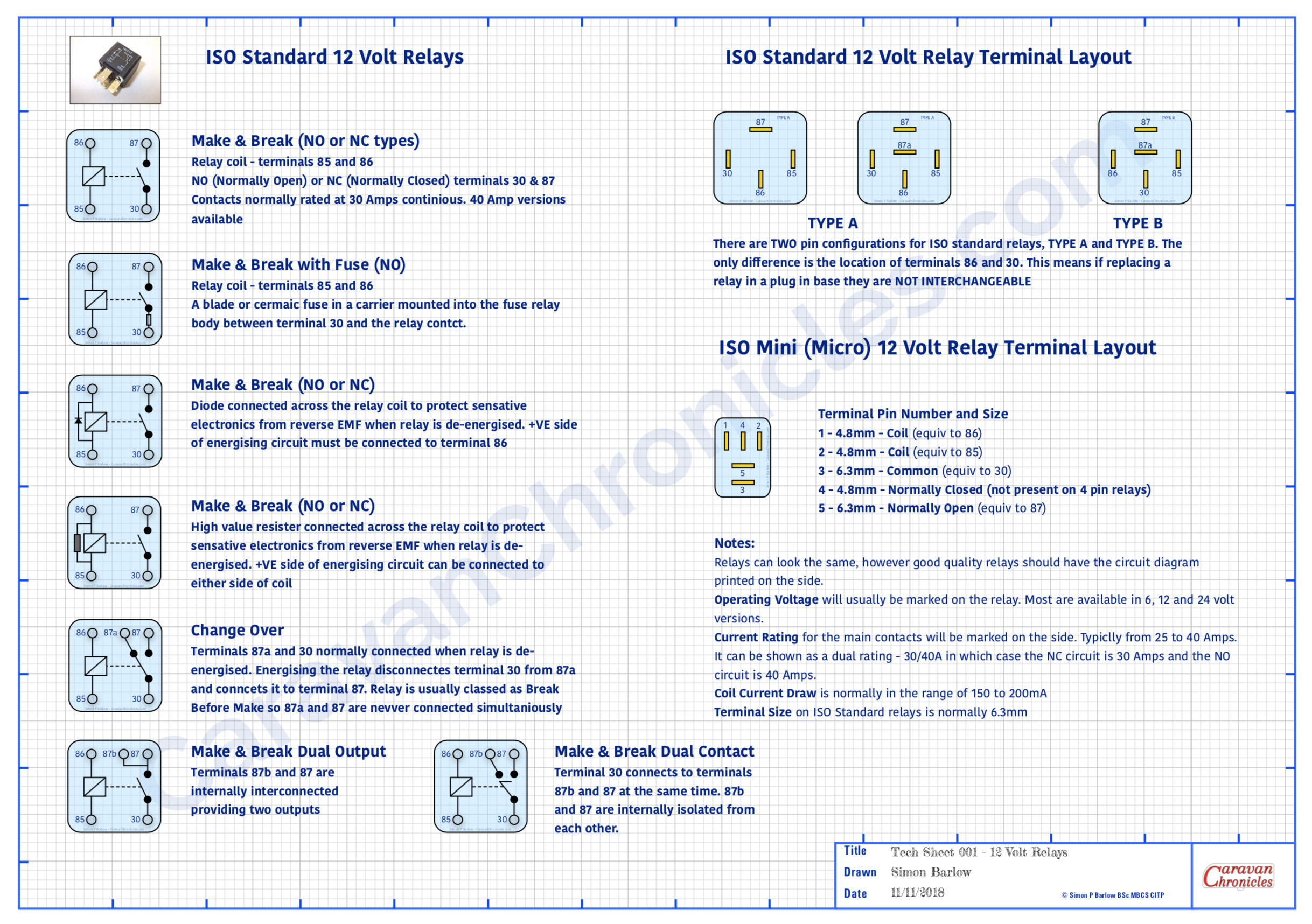
Ok, not one of my usual blog posts. I get a lot of email asking about various electrical items related to caravans and motorhomes and a few things seem to keep cropping up on a regular basis. One is to do with 12 volt relays… what types are there and what are the pin connections.
Another is to do with cable size relating to load and its relation to the length of cable…. “I have a 40 Amp load and its 3 metres from the battery… what size cable do I need?” type questions.
In the past I’ve emailed back with answers, but one caravan engineer asked me if I know of any information sheets that had this type of info that he could put above his workbench.
So I’ve produced a couple of A3 size PDF information sheets (they will print A4) that can be downloaded printed out and pinned up, shoved in your notebook, glued to the lid of your tool box or used to wrap that must have tool present for your beloved caravan or motorhome DIY enthusiast in your life (seasonal eh!)
(I have been told that Office World can print and laminate A3 PDF’s cheaply…. I never knew that!)
I have stylised them as technical drawings and I’ve had to watermark them and some of the icons as I found a lot of my drawings were ending up “as is” or edited on various sites and forums without any credit or link back to Caravan Chronicles. You are free to print out and use them for your own personal use, but if you wish to use them (or any of my drawings) for commercial use, inclusion in blog posts or forums please include a credit line back to CaravanChronicles.com and drop me a line to let me know.
We are just back from Chester Fairoaks after doing the Chester Christmas market and a bit of shopping at Cheshire Oaks Designer Outlet Village and will be adding off to York for a bit more Christmas Market action.
I have a couple of more information ‘posters’ in development but if you have any ideas for future offerings, drop a line in the comments below. Of course my legal advisor – Henry has asked me to point out E & OE
(Everything on the internet is improved by a cat apparently… so here’s Henry)
Sometimes things you take for granted and have in your toolbox of fault-finding tricks are a dark art to others.
I was talking someone through a bit of fault-finding on their vehicle and asked if they had measured the current in the circuit. “No” came back the answer. I asked what type of fuse and rating it was and asked the person to just put their voltmeter across the fuse and tell me the voltage across the fuse. “Ah… that’s about 3.2 amps then” I said.
“How do you know that?”
Simple really – all fuses have a resistance and if you know that you can work out the current from the voltage drop. Even simpler really – there are tables for various fuses that have it all worked out for you. I have a selection collected over the years stuffed into the lid of my tool box, along with a lot of other junk paperwork!
I created a volt drop table based on PEC (Pacific Engineering Corporation) fuses that are supplied as OEM fuses in most Japanese, Korean and European vehicles however it is pretty accurate for almost all other makes of the same type of fuse. I printed mine out, laminated them and added them to the collection in the top of my toolbox.
It’s quite easy to use. Just set your multimeter to read DC mV and read the voltage displayed. Now select the fuse type, in this case an ATO fuse – the most common used in vehicles, caravans and motorhomes and from the chart look down the left column until you see the voltage measurement that matches the one on your multimeter… lets say 0.011 volts (11mV)
The fuse is a red 10 Amp fuse so follow the 0.011 volt line across until you get to the 10 Amp fuse column and read the current figure… in this case 1.3547 or 1.3 Amps. It’s as easy as that, no need to break the circuit to put your multimeter in as an Ammeter.
I have a couple of these cheap handy plug-in ammeter’s… although they do have limitations and only work up to 20 Amps.
Although the table is based on PEC ATO/ATC and MINI fuses (download info below) it is pretty close with most manufacturers fuses and as a general reference for fault-finding will be good enough to 0.1 amp.
If you need to know the actual current through a circuit, you need to use an ammeter and not rely on tables but for general work they are close enough.
These tables also come in handy if you are trying to find out why a battery is draining. Without turning anything on it is easy to run through a fusebox checking to see if any circuits have a current drain on them without having to constantly pull fuses and insert an ammeter, which sometimes can upset or reset the circuit you are working on.
One thing to remember with this test if you’re tracing a fault, is you are only measuring the volt drop across the fuse to determine current. You really need to know how much current you should be drawing. For example, If I was testing the 12 volt fridge circuit fuse and I only got a voltage drop across the fuse that calculates to 6 Amps then I’d know there was an issue somewhere along the circuit as I’d be expecting around 10 Amps or more.
A word from our Safety Officer…
Oscar would like to remind you that working on a live circuit has risks and never attempt to undertake volt drop measurements on mains circuits. Most cheap multimeters do not have the internal protection or fused test leads. Be safe. Be like Oscar.
You can down load the table in PDF format (4 pages) and either print them out or save them to your device from the following link:Fuse Voltage Drop Table
Unfortunately due to a lot of my drawings and text being used elsewhere without credit back to CaravanChronicles.com I’ve had to start putting watermarks on a lot of things. I hope this doesn’t make the table too difficult to read.
P.S. Someone told me that everything on the internet can be improved by cats and my “likes” would go through the roof!
After a quick four-day break at the Caravan & Motorhome Club’s site at Wirral Country Park (excellent by the way… already trying to work out when we can go back!!) and a bit of work getting in the way it was time to get going again not he catch can… really it should be called the “Air Oil Separator” Install.
Last time, I’d decided if IKB would have been shaking his head… then it wasn’t right. I decided to make a new bracket out of 1.8mm aluminium sheet and go into full on origami mode. (ps.. after the last post someone emailed me asking what IKB was…. Mr Brunel was not pleased).
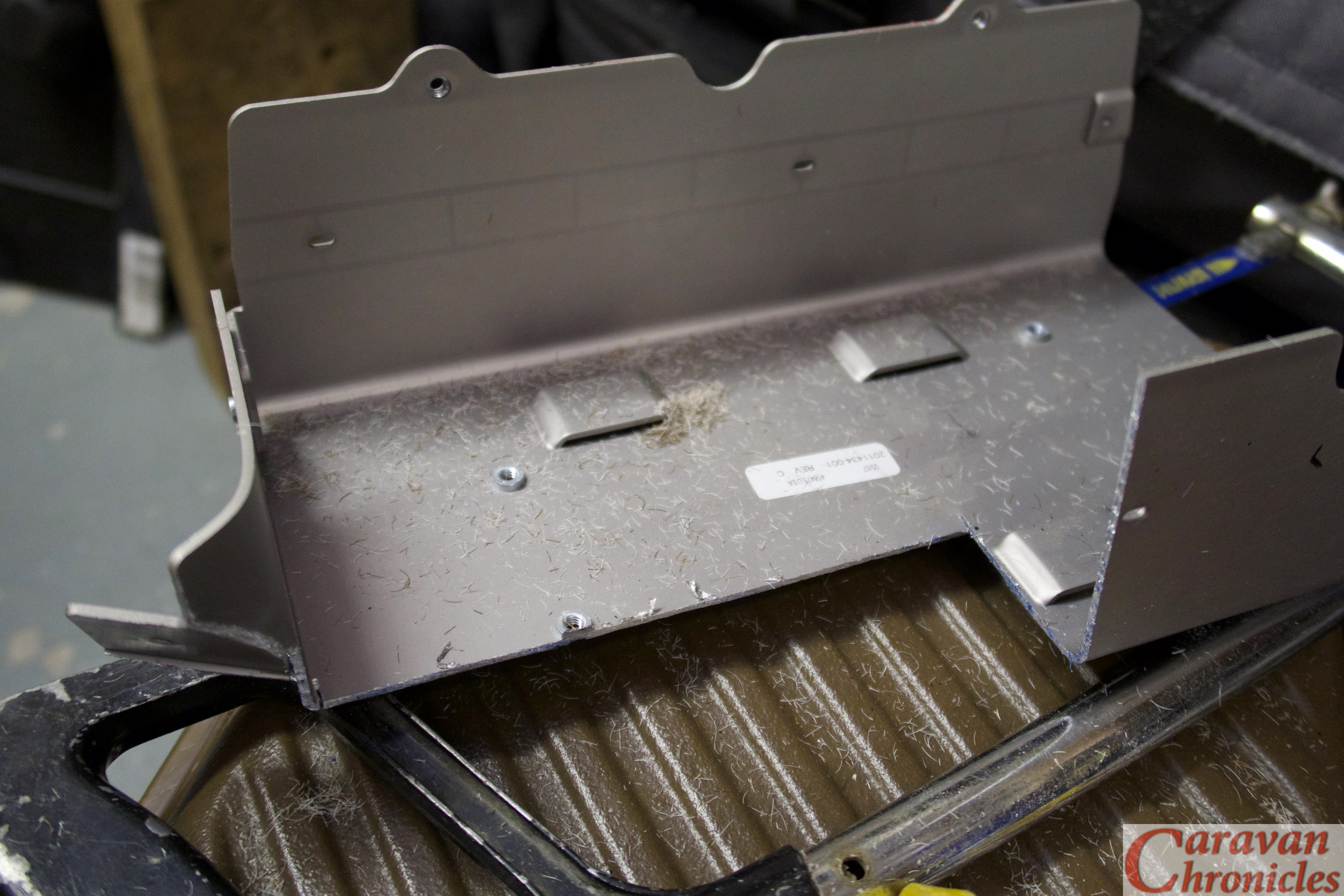
I wanted to make a bracket that passed under the air con pipe and bonnet cable release fitting so that it cleared everything and gave good access at the same time. As a test I did a trial bend if some 1mm thick steel I had just to get the shape…
Once I’d got the angles and size sorted it was time to move on to the aluminium sheet. My press brake… well I call it a press brake, in reality its a cheap basic hand folding machine but it works very well as long as you know its limits and don’t get daft trying to fold big stuff. It was all about the angles…
The first two were easy and I could form the lip with two folds, the second was less than 90 degrees so I just about got away with enough clearance. However folding the return that would lip over the front cross brace which was also less than 90 degrees also meant that I’d have a problem fitting it in the folder.
However, a little lateral thinking and taking the blade off the folding machine, inserting my workpiece and re-installing the blade meant I could fold in the opposite direction (downward)… result!
A quick trim and rounding off the edges gave me a rough folded bracket. A quick file of the edges and work-over with some fine emery removed all the tool marks… quickly followed up with a coat of etch prime to protect it.
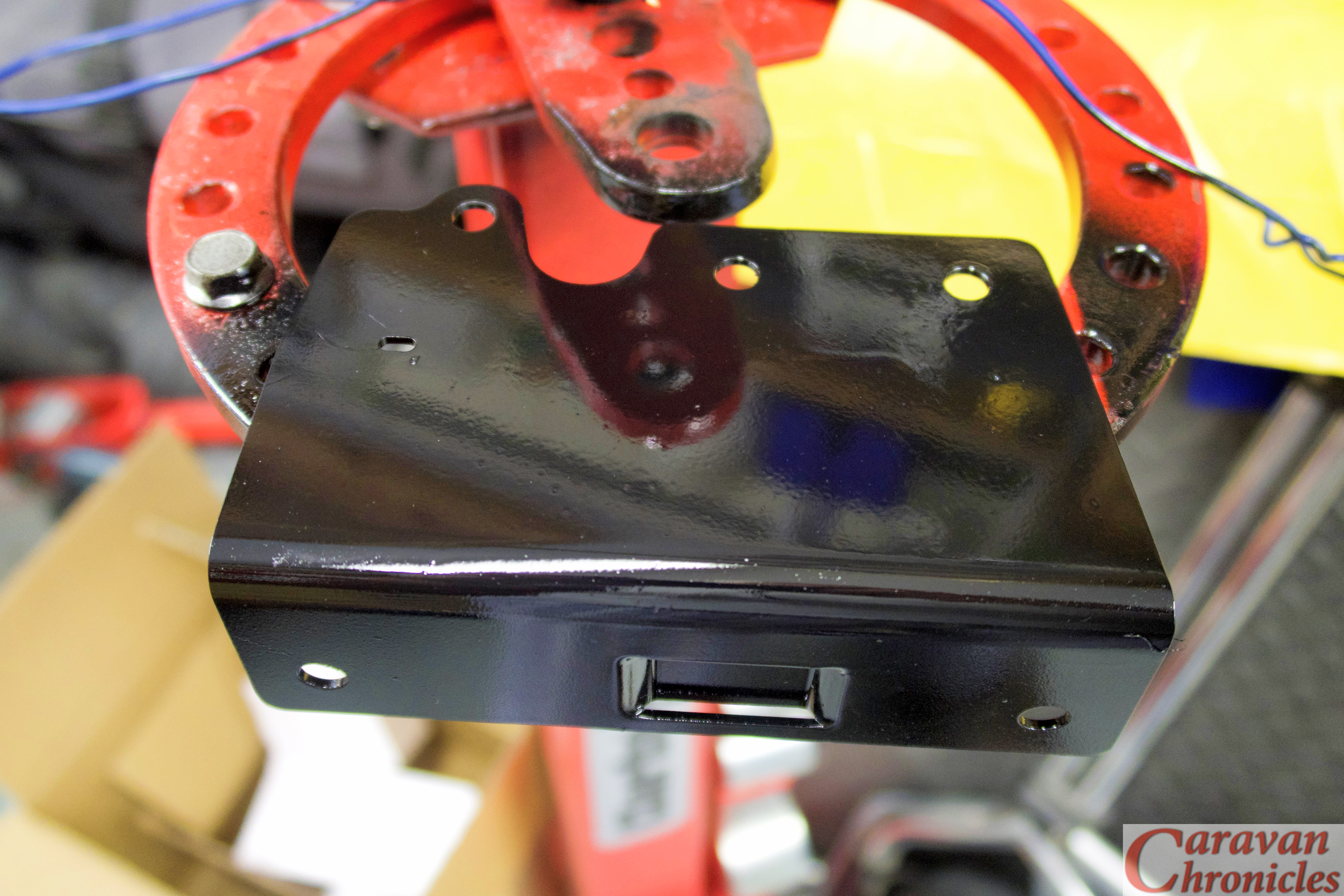
I now had to work out how to mount the plastic housing the bonnet release cables were located in. On the rear of the fitting were two plastic tabs that locked into two square holes punched into the vehicles cross member.
So a few minutes spent with a dremmel and a couple of suitable sized swiss files later…
… and the piece was ready for a final rub over with scotch bright a second coat of etch primer and two coats of black.
The Installation…
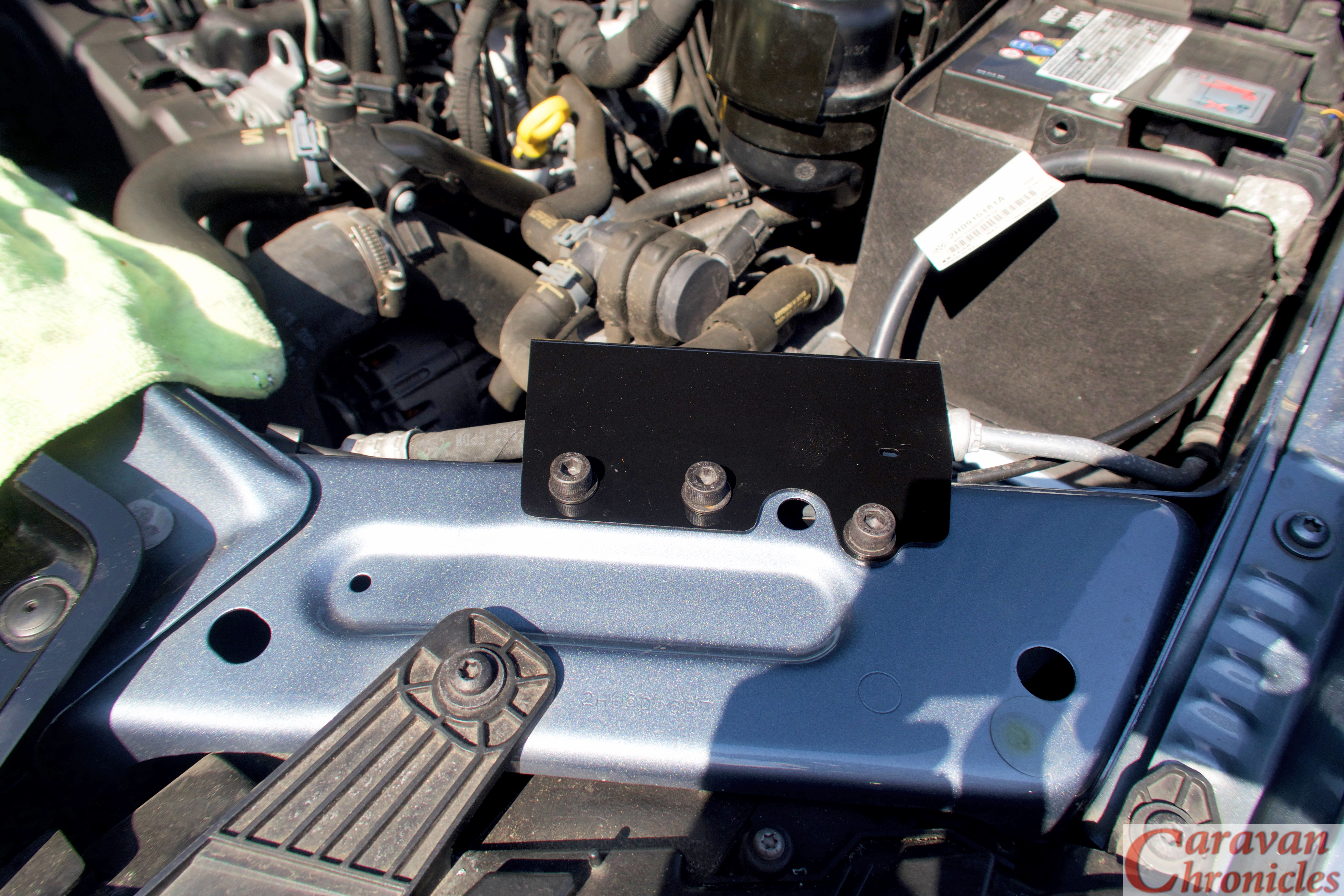
All went a bit easy actually… which is flipping’ unusual for me. I released the bonnet (or ‘hood’ for my American friends) cable fitting and simply clipped it back in to the two new holes I’d made.
The Provent was installed next…
… again without any issues. Next was to sort out the plumbing.
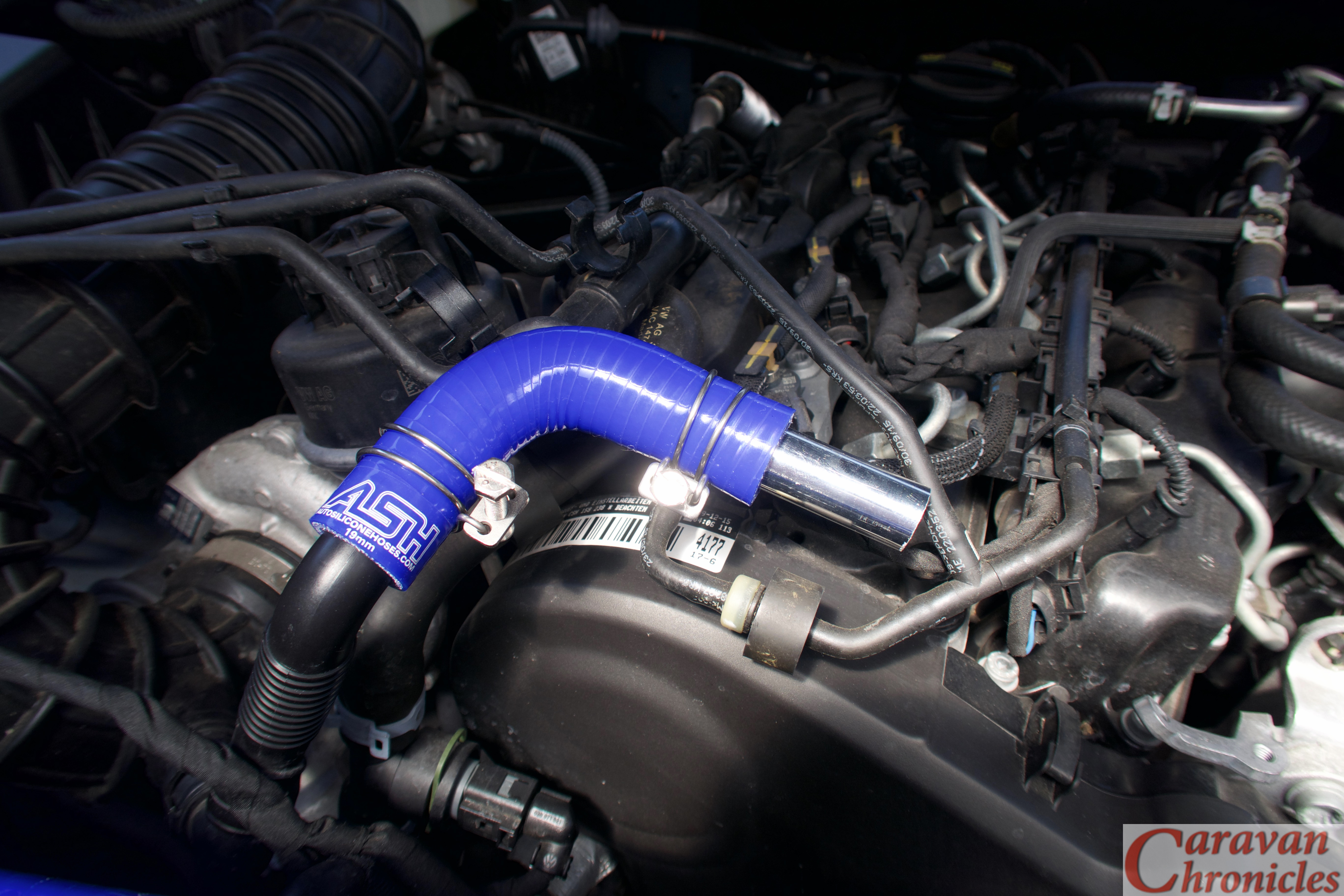
I’d done a bit of research and asking around and the guys at ASH… AutoSiliconHose.comhad come highly recommended. So a road trip over the Pennines to Mirfield (just east of Brighouse in West Yorkshire) was scheduled.
I had a basic list of what I thought I’d need and the chap behind the counter hooked me up with everything… including the alloy couplers he cut to size while I waited. Great service from ASH and I can definitely recommend them.
Back home with my shopping, it was time to start on the plumbing.
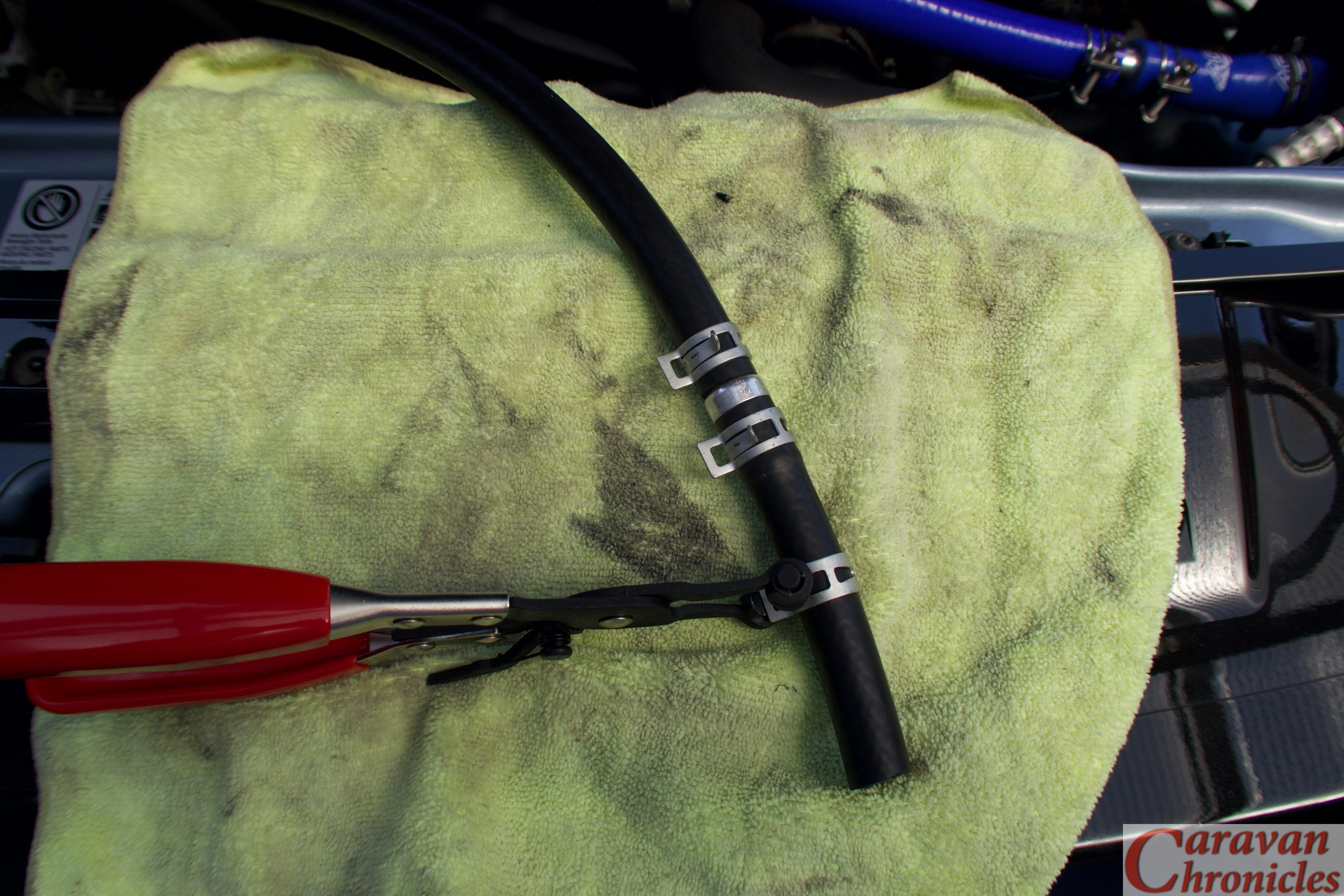
For securing pipes, I personally prefer spring clips… the type you install with special pillars, however the silicon hose OD was slightly too large for may normal stock of clamps so I had to opt for using the wire type. I’ll order some of the correct size and replace the wire clamps as soon as they arrive.
It was really simple now to just assemble the bits, cutting the silicon pipe to length as required. I used a pair of plastic conduit cutters to easily slice through the pipe.
Before I made the final connections to the crank case breather port or the turbo inlet port I blew the pipes clear using a high pressure air line.
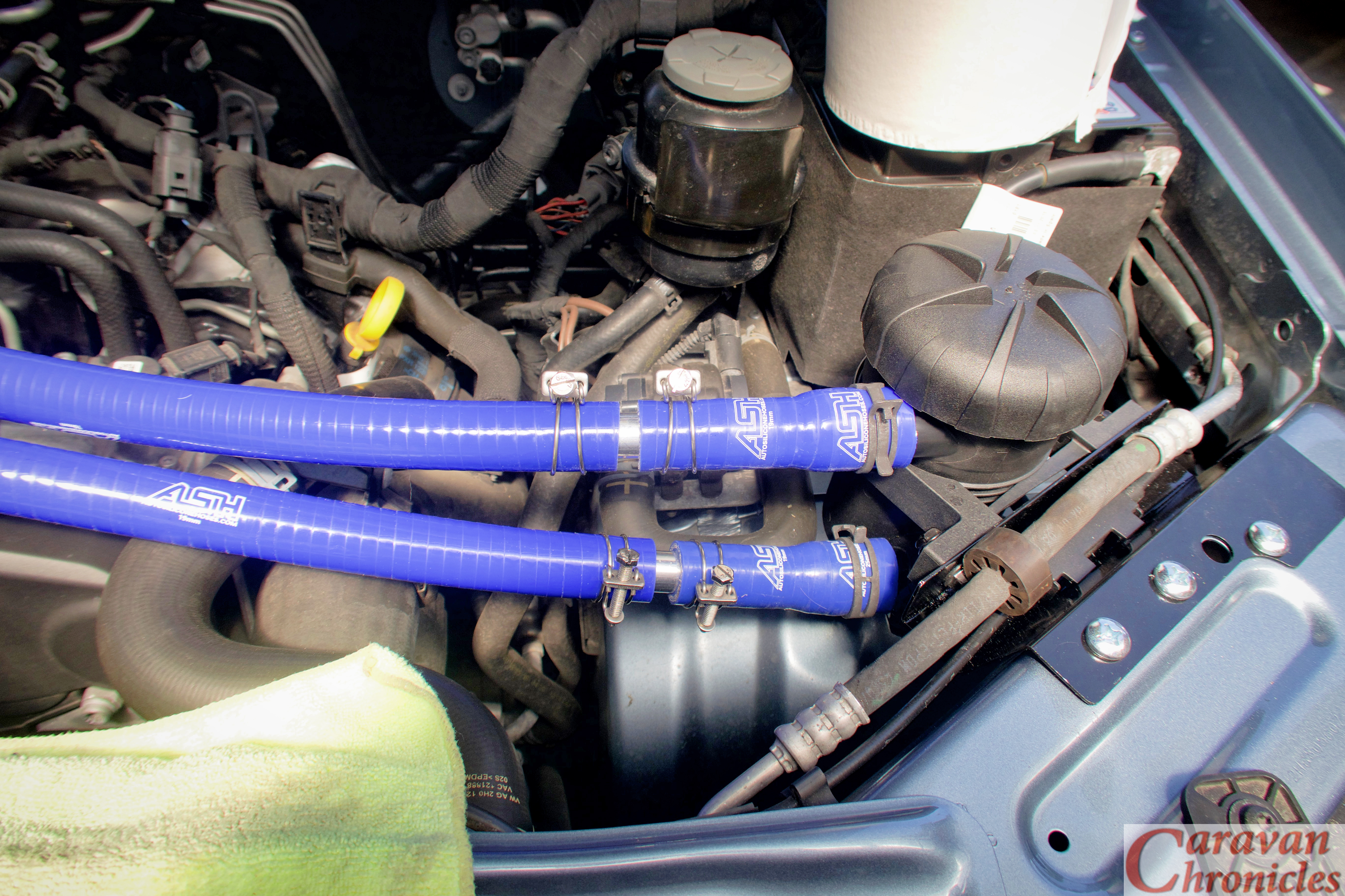
All that was left to do was install the drain hose, one way valve and drain tap. I used normal 20mm oil line for the drain, inserting the one way valve about three inches below the outlet of the Provent catch can. The remainder of the hose was dropped down to chassis level and the drain tap added and secured with a couple of zip ties.
The Finale…
I secured the pipes in a couple of places with zip ties, now I know the route I can make a small stand-off bracket with two rubber lines “P” clips to mount on the engine to hold the pipes, although they are self-supporting because of the short length.
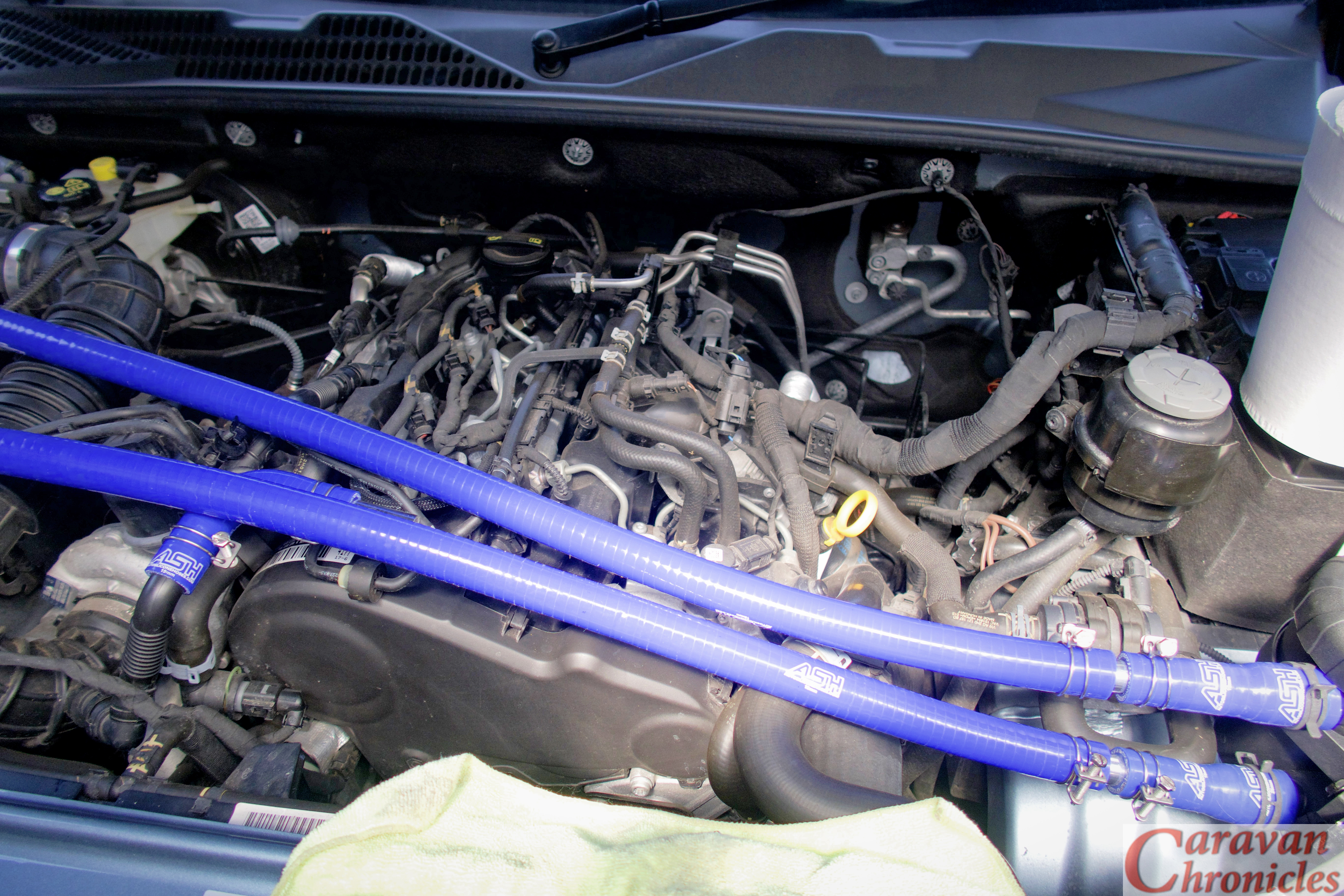
In the photographs above it looks like the piping is tight across the engine, I did do a pull and push test and there is plenty of movement at the 90 degree bends to allow the torque twist of the engine without pulling or pushing on the pipes at the catch can end.
The current mileage is 11,750 or there abouts, so I’ll check the drain and filter in 100 miles and each 100 miles after that so I can get an idea of how the setup is going. I’m not sure how long the filter is designed to last, but Ill put it on the schedule to replace ever main service. The other thing that is an unknown is how much oil I’ll get. I have been watching some YouTube videos made by Berrima Diesel in Australia (if you watch any of the Australian 4 x 4 or off-road channels you will recognise the name). I only found out about their catch can experience when one of the guys from one of the 4 x 4 adventure channels got in touch… even if you don’t think you need a catch can but drive a big diesel their videos are well worth watching.
Ok… I was saying I don’t know how much oil to expect… but it did surprise me that Berrima Diesels posted a video showing a new 4 x 4 with about 6000Km on the clock had produced about 300ml’s of oil using the same Provent catch can. It’s also worth taking look at what the have to say about the current oil specified in diesel engines.
The other thing I noticed was when I left the engine ticking over for about ten minutes. Bearing in mind I had just come back from West Yorkshire via the M62 and M60 and started the pipe install as soon as I got back so the engine was still hot, the difference in temperature between the short length of pipe exiting the crankcase vent and the inlet pipe of the turbo. The pipe exiting the crankcase vent port was almost at the temperature I could not keep my fingers on it, while the inlet pipe I’d connected too was still cool. I’ll have to get my thermomiterbob laser do-hicky out and get some readings… but anything that helps cool gasses going into the turbo has to be of benefit right?
That’s it for now, I know it’s not caravanning related that much… unless you want to get the best out of your diesel while towing. I promise the next one will be caravan related, honest!
As in part one I’d also like to give a shout out to Charles at HumbleMechanic.com for all the information and videos he produces about VW vehicles. Charles has been an absolute gold mine of information for all things VW and if you drive any of VW’s vehicles please be sure to drop in on his YouTube channel and take a look.
I’m installing a “Catch Can” can on our VW Amarok and this little posting is all about it, but first a bit of history on why I’m installing one.
If you look at modern high performance diesel engines one of the things that they do to reduce emissions is have a number of systems to reduce the harmful emissions. EGR or Exhaust Gas Re-circulation wich is feeding part of the engines exhaust back into the intake but probably the most widely known is the DPF… or Diesel Particulate Filter which captures fine soot particles from exiting the exhaust. The DPF needs to be cleaned regularly, through a process called regeneration. Either active, passive or forced, the accumulated soot is burnt off at high temperature (around 600°c) to leave only a residue of ash, effectively renewing or regenerating the filter, ready to take on more pollution from the engine. To regenerate, the vehicle electronics adjust the timing of the engine to increase the exhaust gas temperatures or commonly it can be achieved by passive regeneration usually on the motorway when exhaust gasses are generally hotter.
In city driving or short trips the regeneration my not take place fully, leading to blocking of the filter. This can lead to higher fuel consumption and a visit to the mechanic for cleaning or replacement.
Forced Regeneration
If the DPF become blocked you will get an engine warning light and/or a DPF warning light to let you know that a regeneration or cleaning is required. If the vehicle continues to be driven and the engine load is not enough for the automatic process to be initiated you will get a second stage DPF warning. When your vehicle displays second stage DPF warning lights it will usually go in to ‘limp mode’ and should be taken to the dealer to ascertain the extent of the problem.
A forced regeneration involves the garage using a computer program to run the car, initiating a regeneration of the DPF. This will also usually require changing the engine oil & oil filter.
Why does my Diesel Particulate Filter (DPF) block
Problems arise around town with stop start driving where the regeneration process might not complete or the engine never get hot enough for a long period. A warning light will illuminate or a message indicating the DPF is full displays on the dash. If you continue to drive in the same manner, the soot build up will increase until other warning lights illuminate and the vehicle will go into ‘limp’ mode, where driving speed is restricted.
Crankcase Ventilation
In all piston engines a certain amount of ‘blow by’ happens, this is some of the hot gasses treated in the cylinder combustion leaking past the piston rings.. or ‘blowing by’ and entering the crank case in the sump area. This pressure needs to be released and twenty years ago the engine oil filler cap used to have e vent in it. However in modern emission controlled vehicles this is not acceptable and the excess pressure is vented into the air intake of the engine where it passes through the engine cycle and exits through the exhaust. These hot gasses passing through the sump on their way out pickup fine mist of oil from the sump which is carried through to the intake of the engine and this creates three problems. The first is a sticky residue build up on the intake valves that hardens with temperature – especially on direct injected engines. Secondly the intake pathway gets coated in oil from the engine. If you have a turbo charged engine with an intercooler, this can become an issue as it reduces the heat exchanging effects of the intercooler. Thirdly, when the oil is burnt in the engine it creates a heavy soot that increases the build up in the DPF.
When towing, you generally use more power for accelerating and maintaining speed which is great in one respect for the DPF. The downside though is the piston blow by is more and therefore the crank case pressure is increased.. picking up more of that fine oil mist from the sump.
Now the diesel engine tuning guys and the 4 x 4 guys in Australia have known about this for a number of years and they have a solution to the problem.
Cleaning up the crank cases gasses – “Catch Can’ or Air Oil Separator?
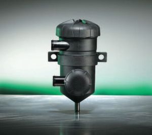
There is a difference. a ‘Catch Can’ is usually just that. A can that the gasses are fed into with an outlet that is fed back into the turbo inlet. Some do have some form of baffle but a lot don’t. More expensive ones may have a gauze wad inside for the oil droplets to form on. A lot don’t have a drain, you have to remove the bottom of the can to empty it. If you look on auction sites you can find nice looking anodised aluminium ones for £20 or £30 but for that sort of money all you are really paying for is the nice looking anodised aluminium. Not for an efficient effective unit.
On the other hand, a true Air Oil separator will have multiple traps in the form of differing size materials making up membranes for droplets to form on. A number of them are designed to swirl the gasses around first before exiting through the centre after passing through the filter membranes.
I wanted to get as much oil out of the gasses before they enter the engine inlet. So I opted for an Air Oil separator with replaceable membrane filter rather than a cheap ‘catch can’. Seems like a simple device really, but there are a few more things to take into consideration…
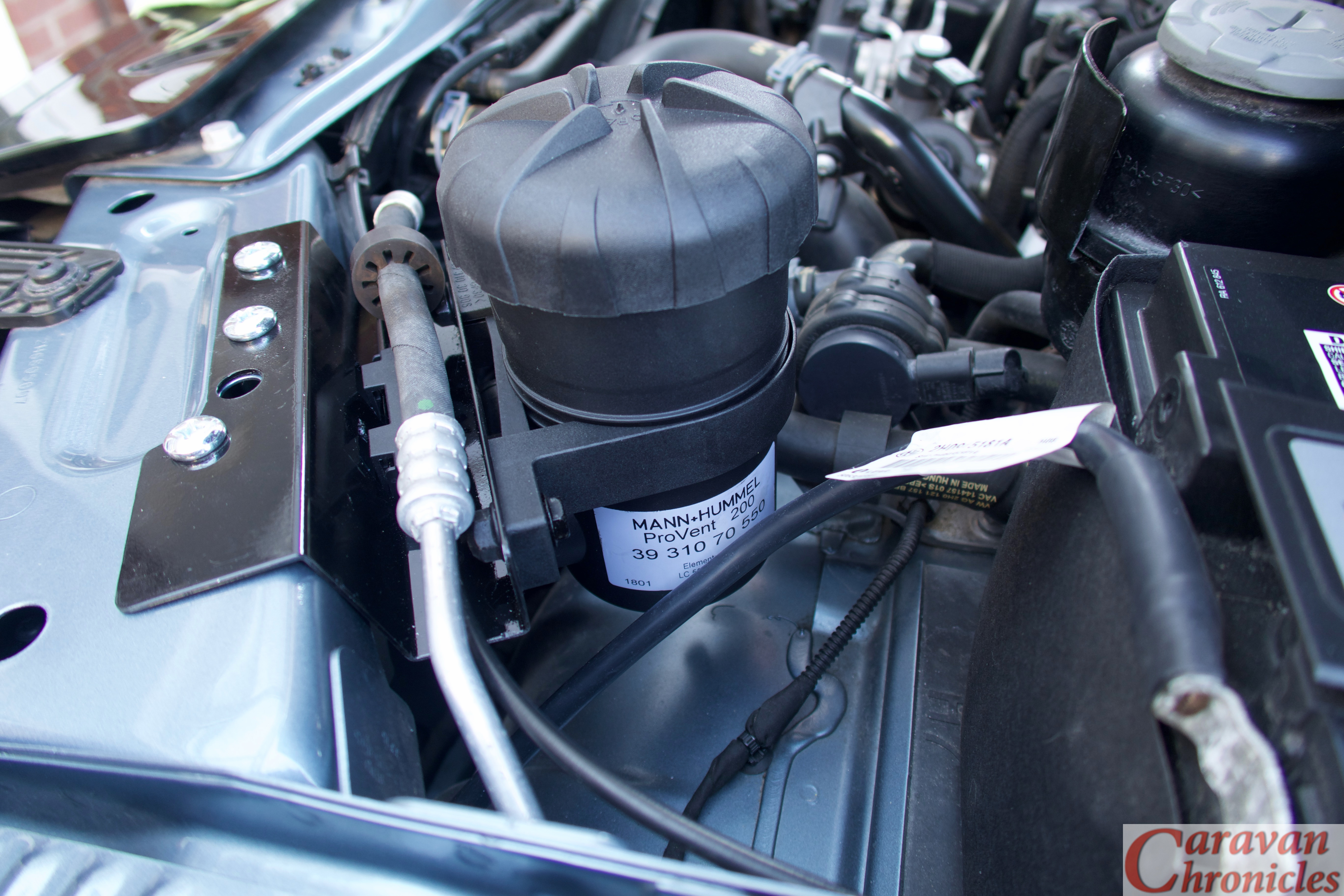
I’ve opted to use the Mann-Hummel ProVent 200 on our VW Amarok. It’s been used all over the world with hundreds of installations on Toyota’s, VW’s, Mitsubishi’s, Land Rover’s and not just on 4 x 4’s.
My hope is that I’ll reduce the emissions through the engine while prolonging the life of the DPF, keeping the inlet clean and oil free and importantly preventing that soot and carbon buildup in the inlet ports and valves while maintaining the efficiency of the intercooler.
Getting Started
I did look at the kits available for the VW Amarok and all were sourced in Australia. However I could buy all the individual components in the UK a lot cheaper than importing a kit. Bit’s ordered, the first decision was where to locate the unit…
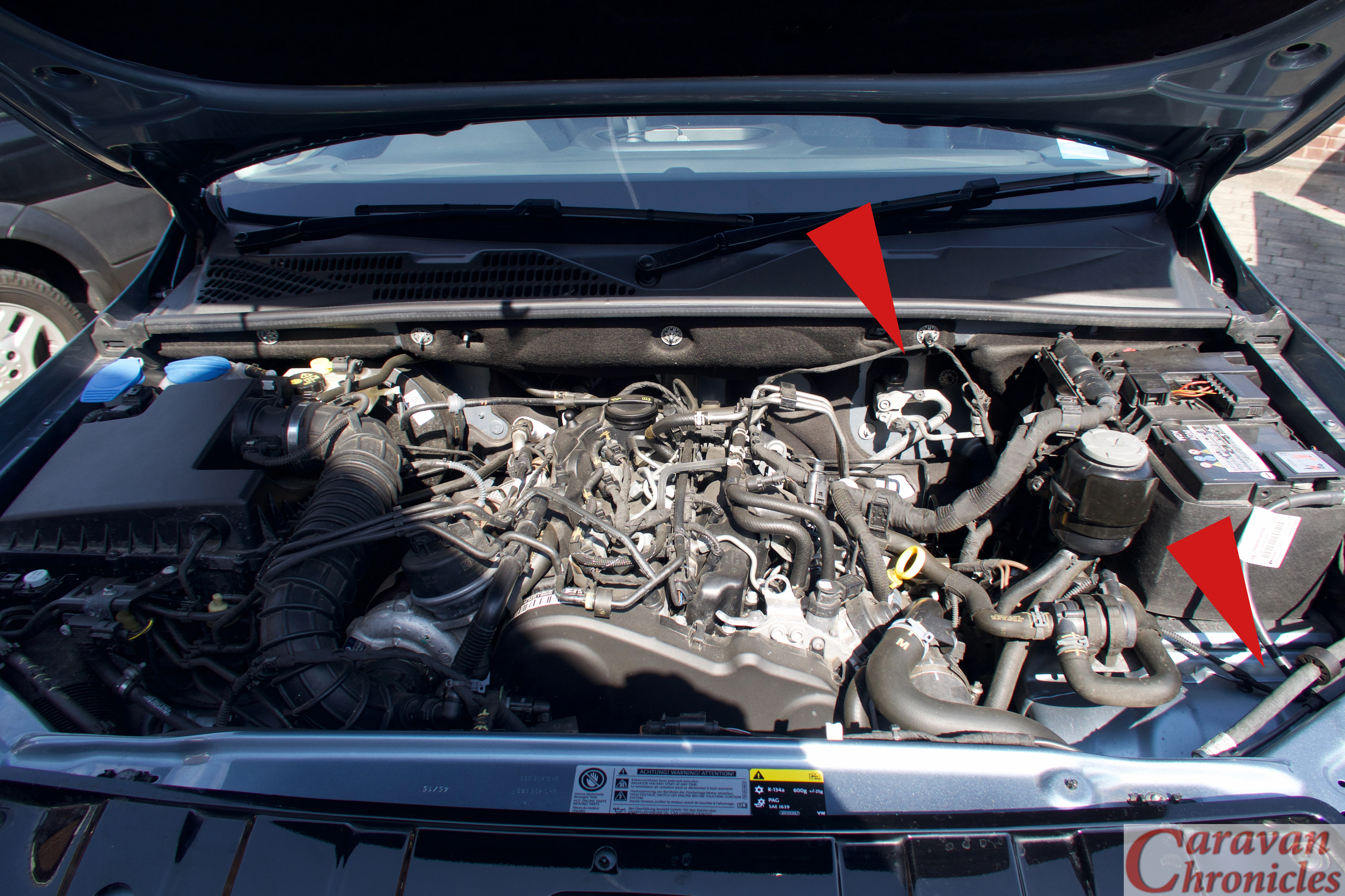
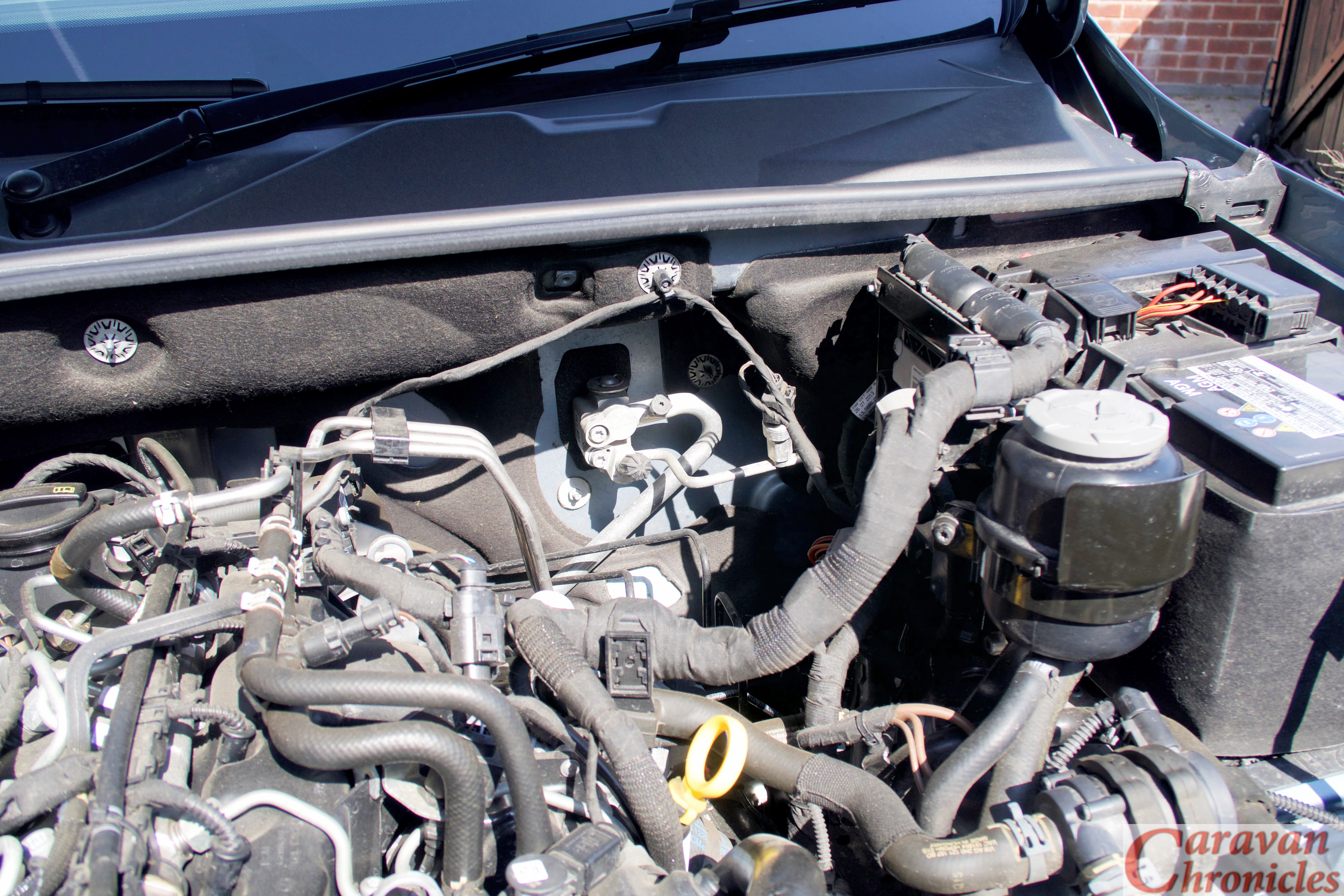
In the Amarok’s engine bay there is only two real places viable for the location of the ProVent. The first is on the back wall next to the engine ECU which seems to be the place of choice for most of the kits I’d found, and the second is in the front right hand corner in front of the battery.
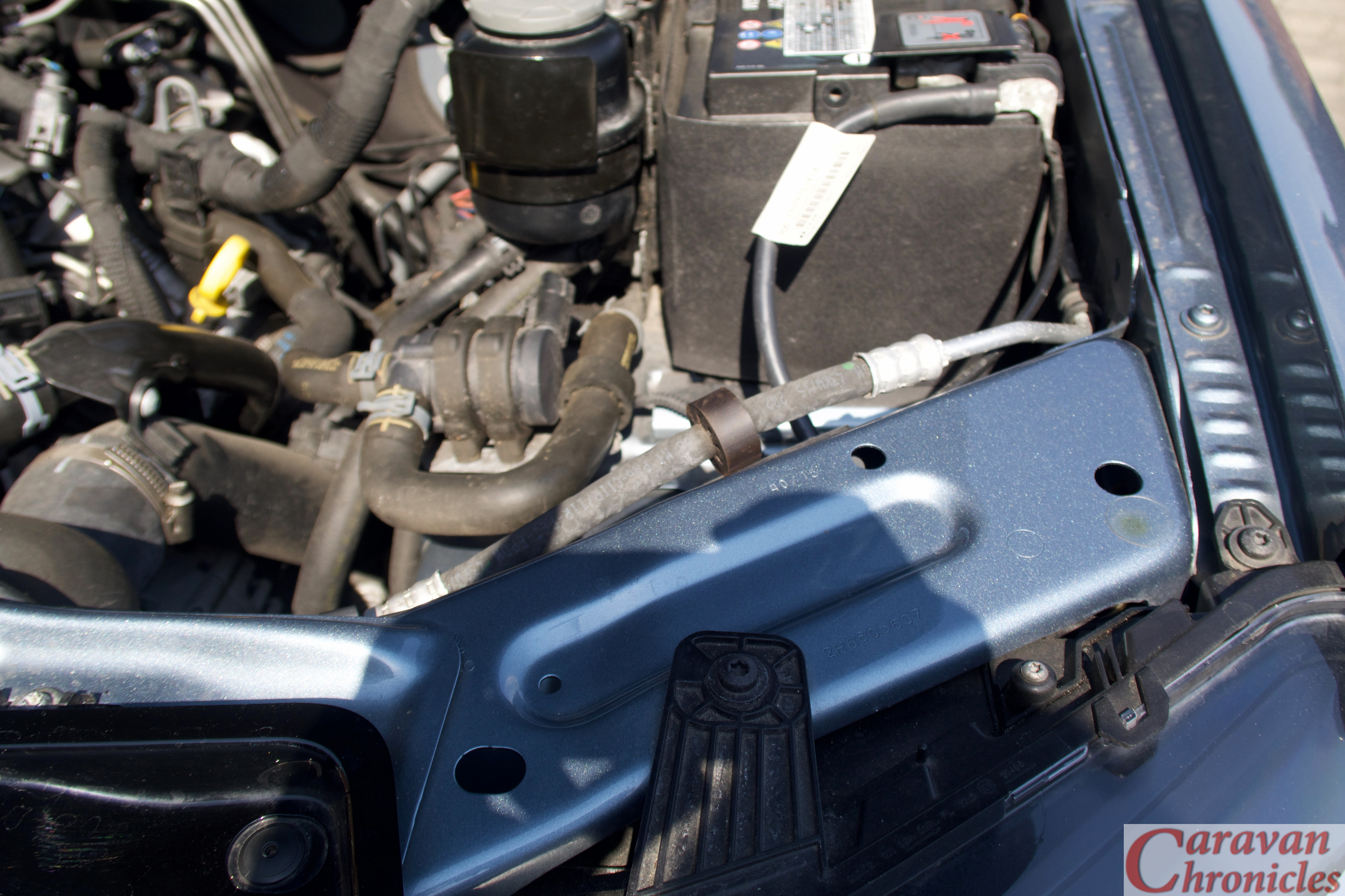
Installing it on the rear firewall next to the ECU would mean partially covering up the Air Con gassing ports and I just knew that would be asking for trouble in the future…
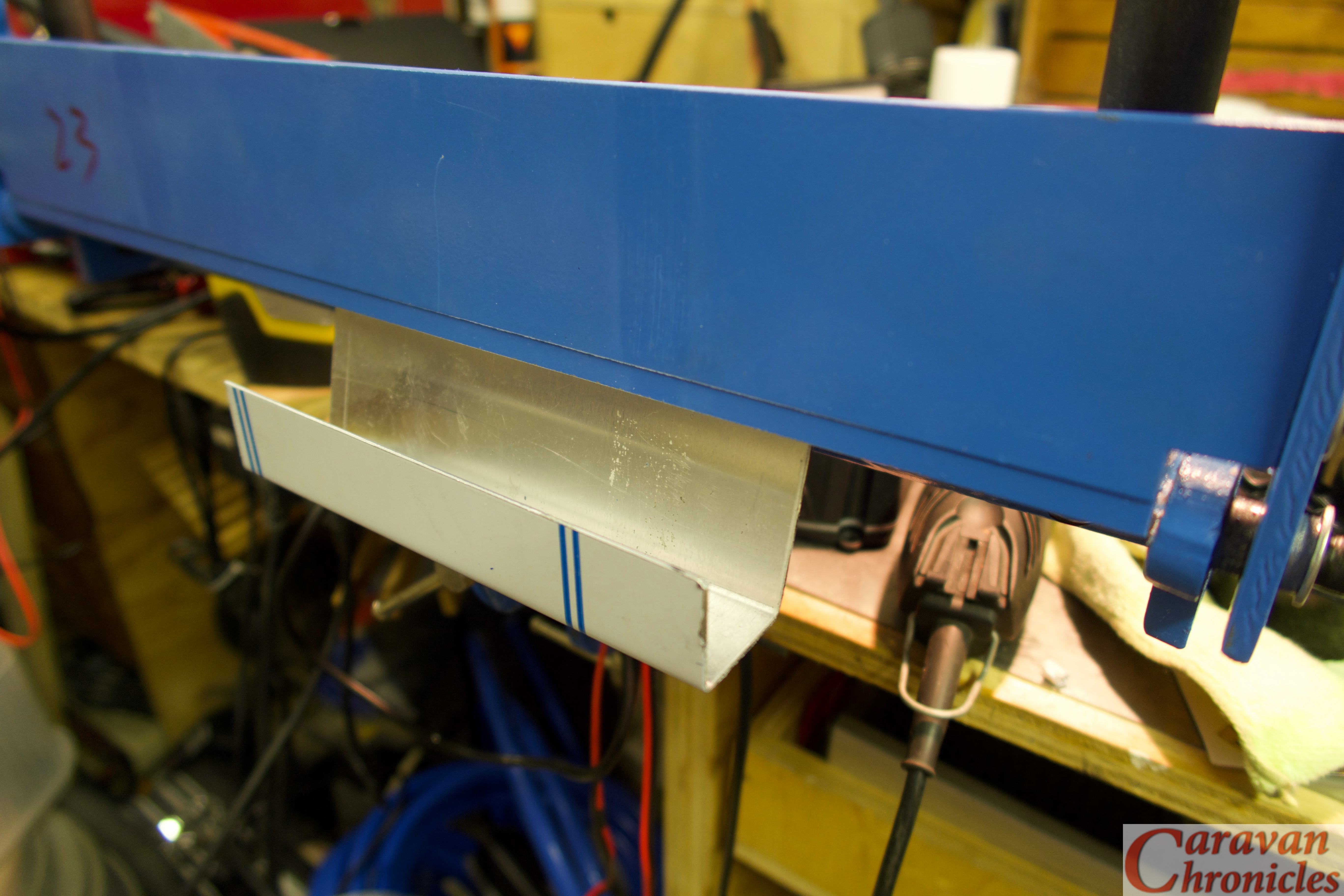
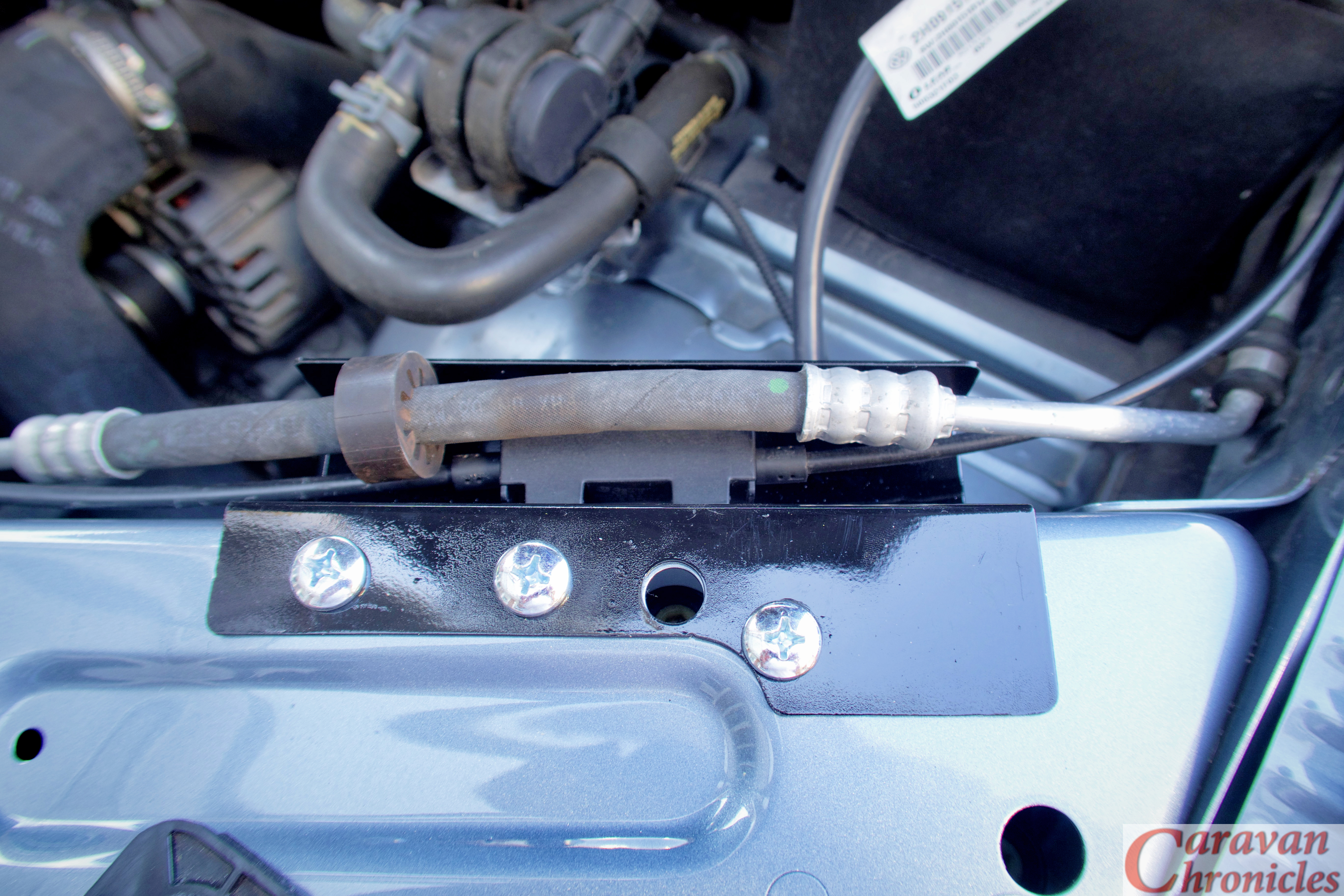
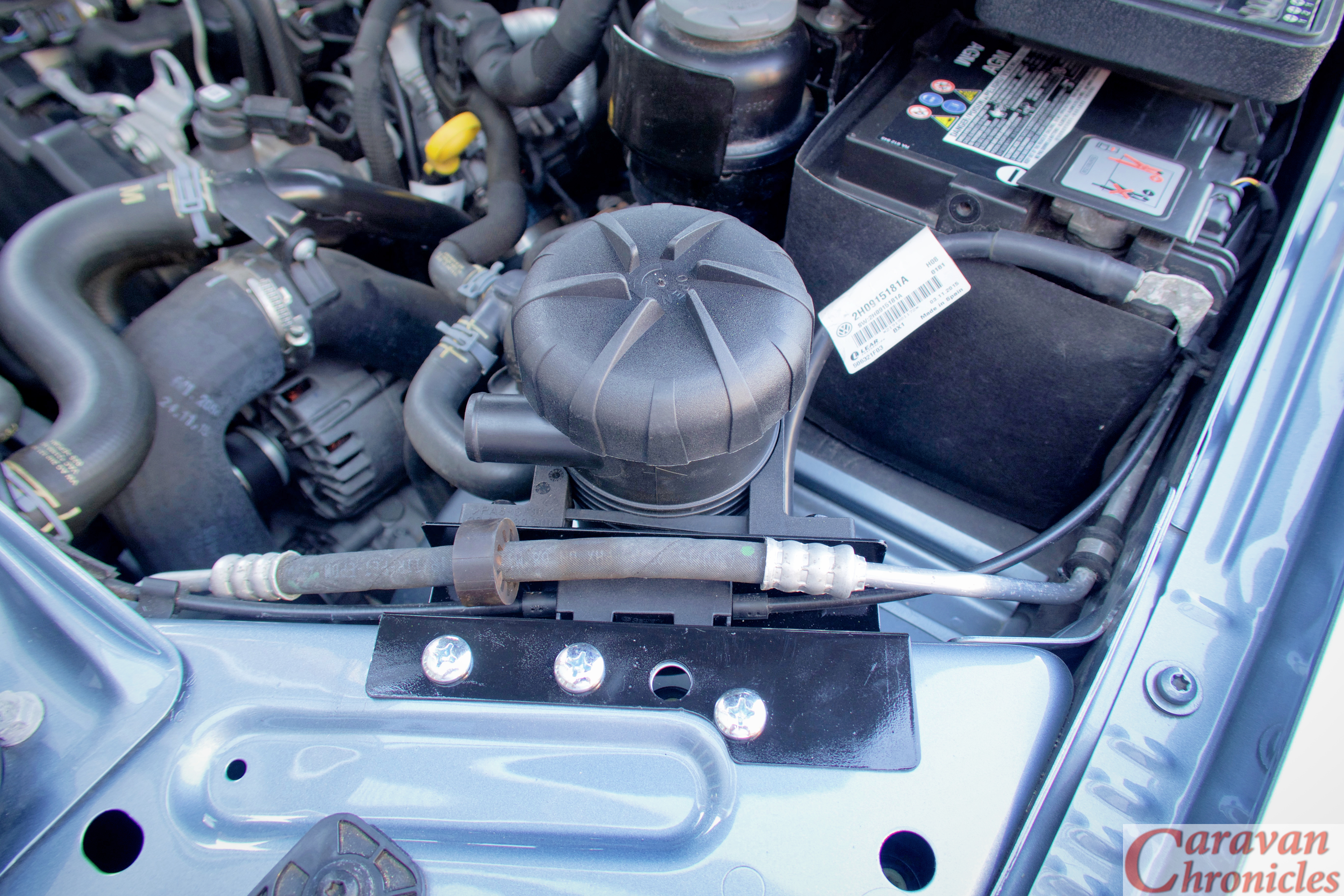
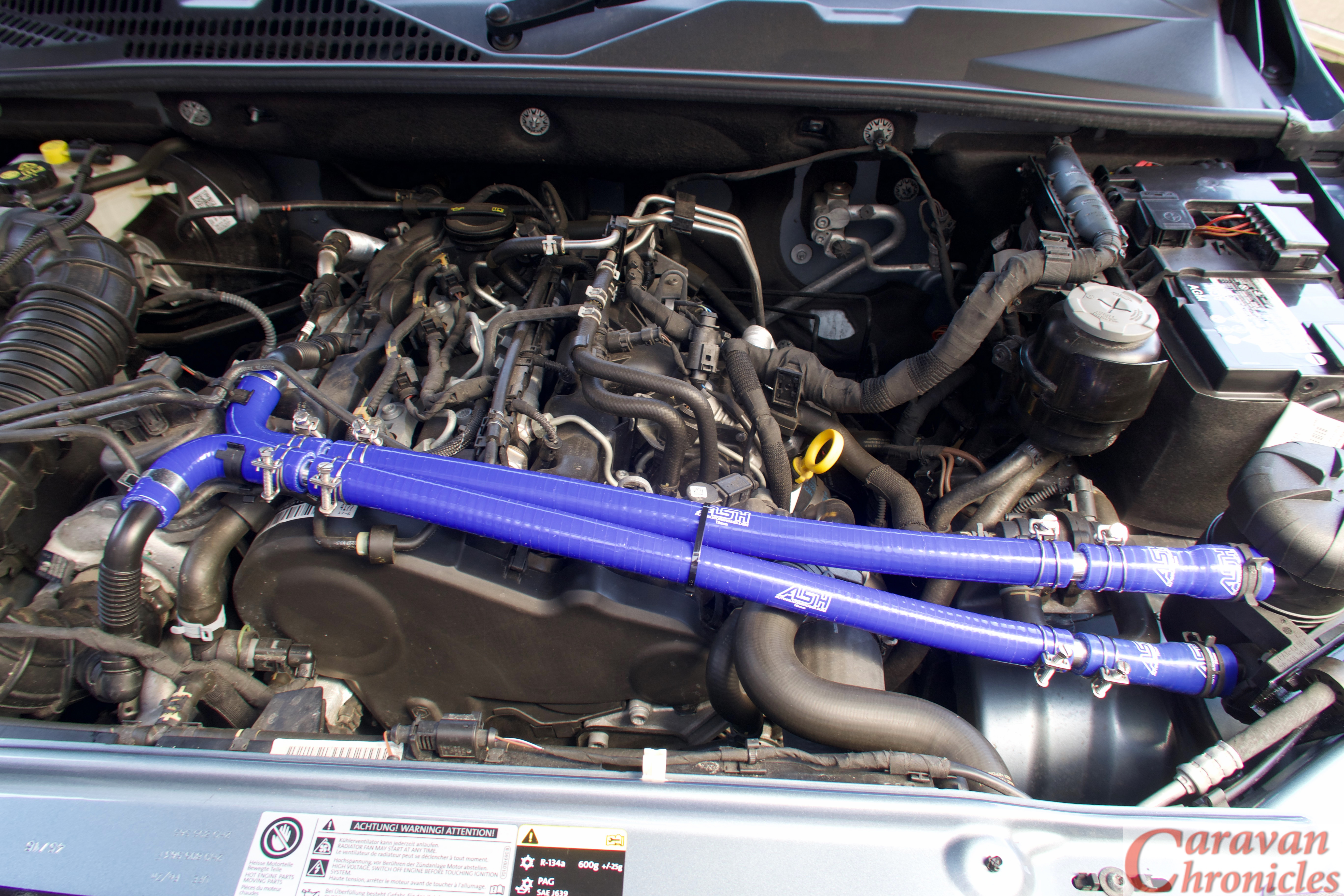
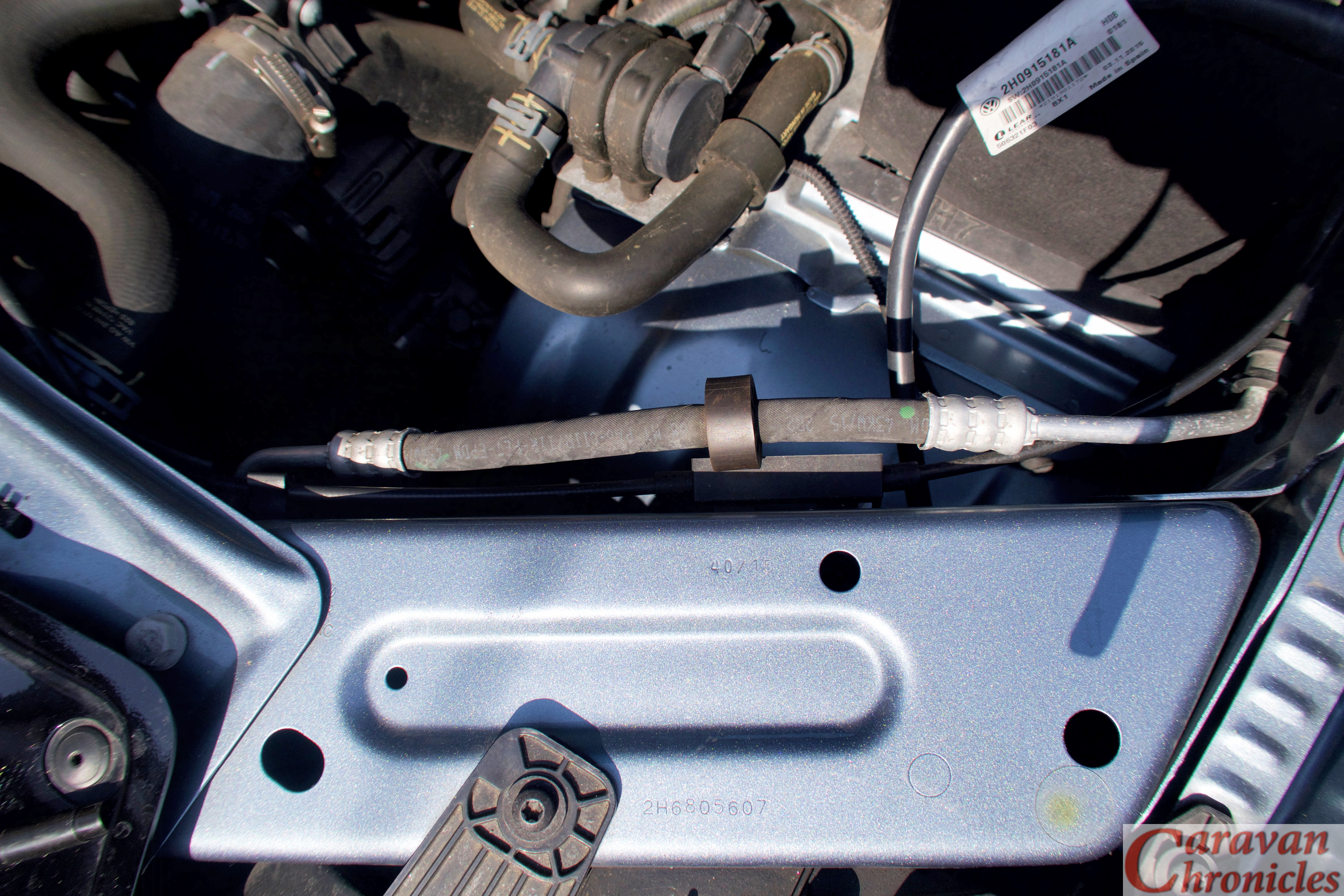
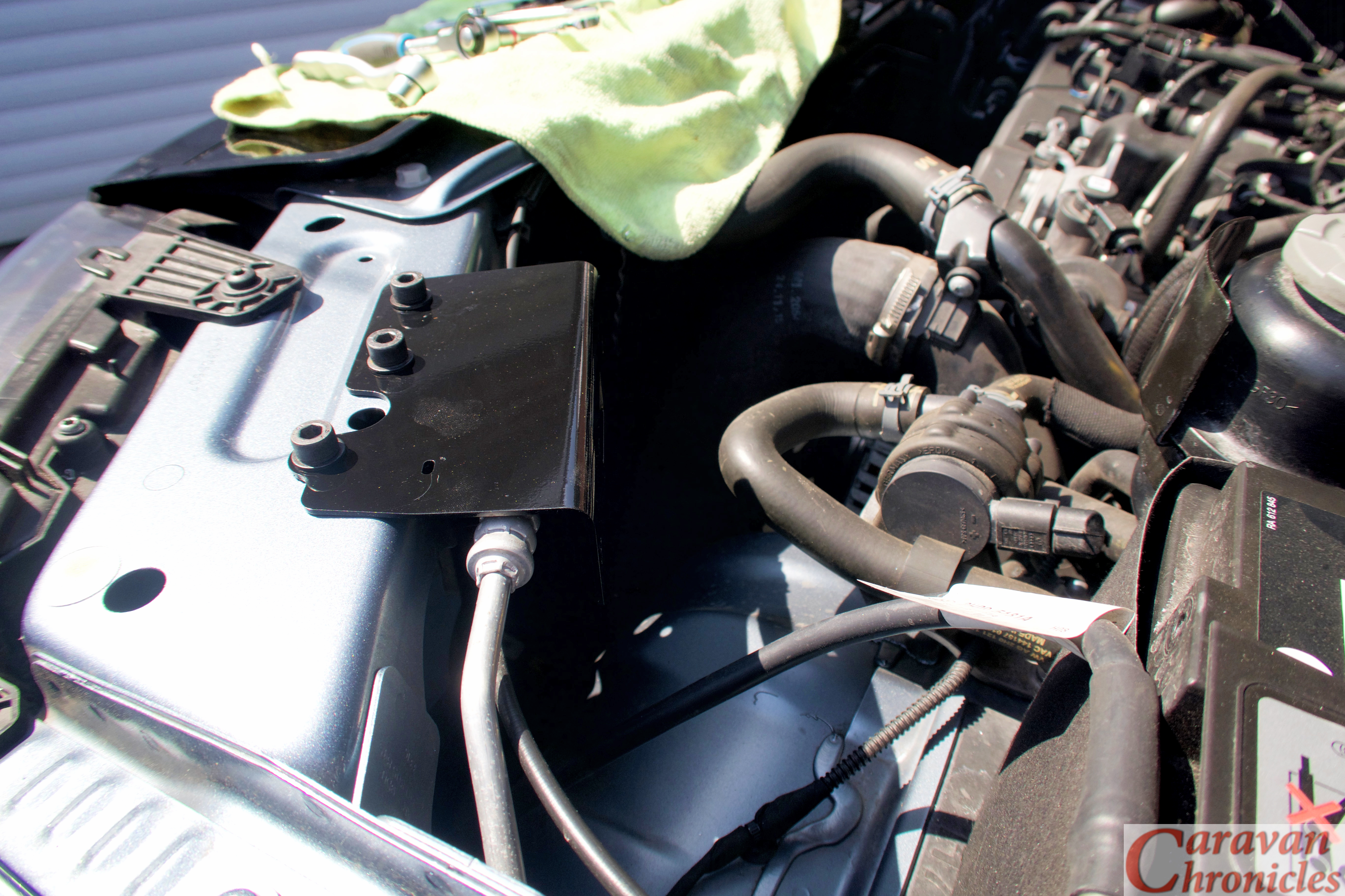
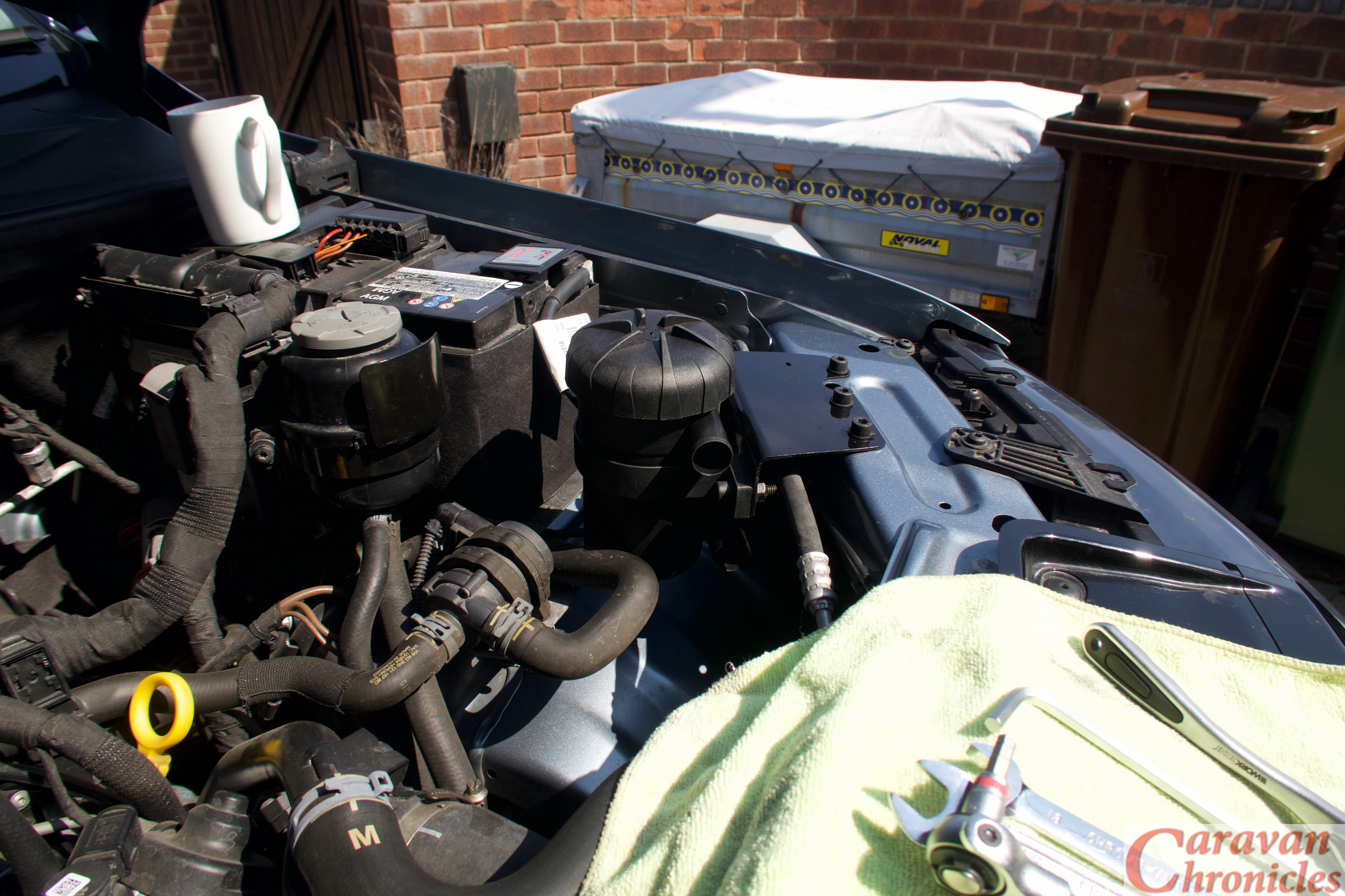
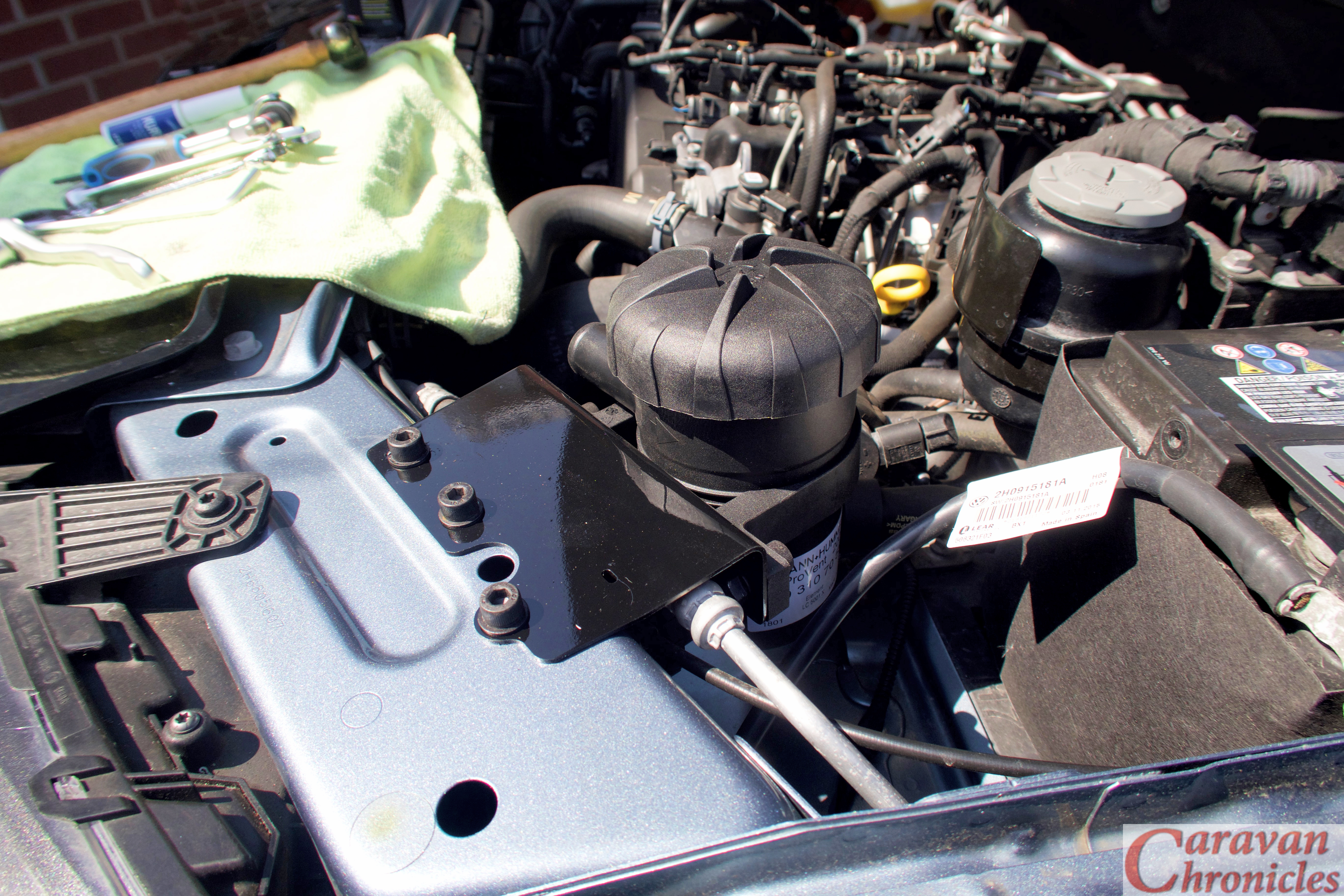
So the location that in my mind seemed the most logical would be to mount it in front of the battery, manufacturing a suitable bracket to hang it off the front top cross-piece where there seemed plenty of room and easy access.
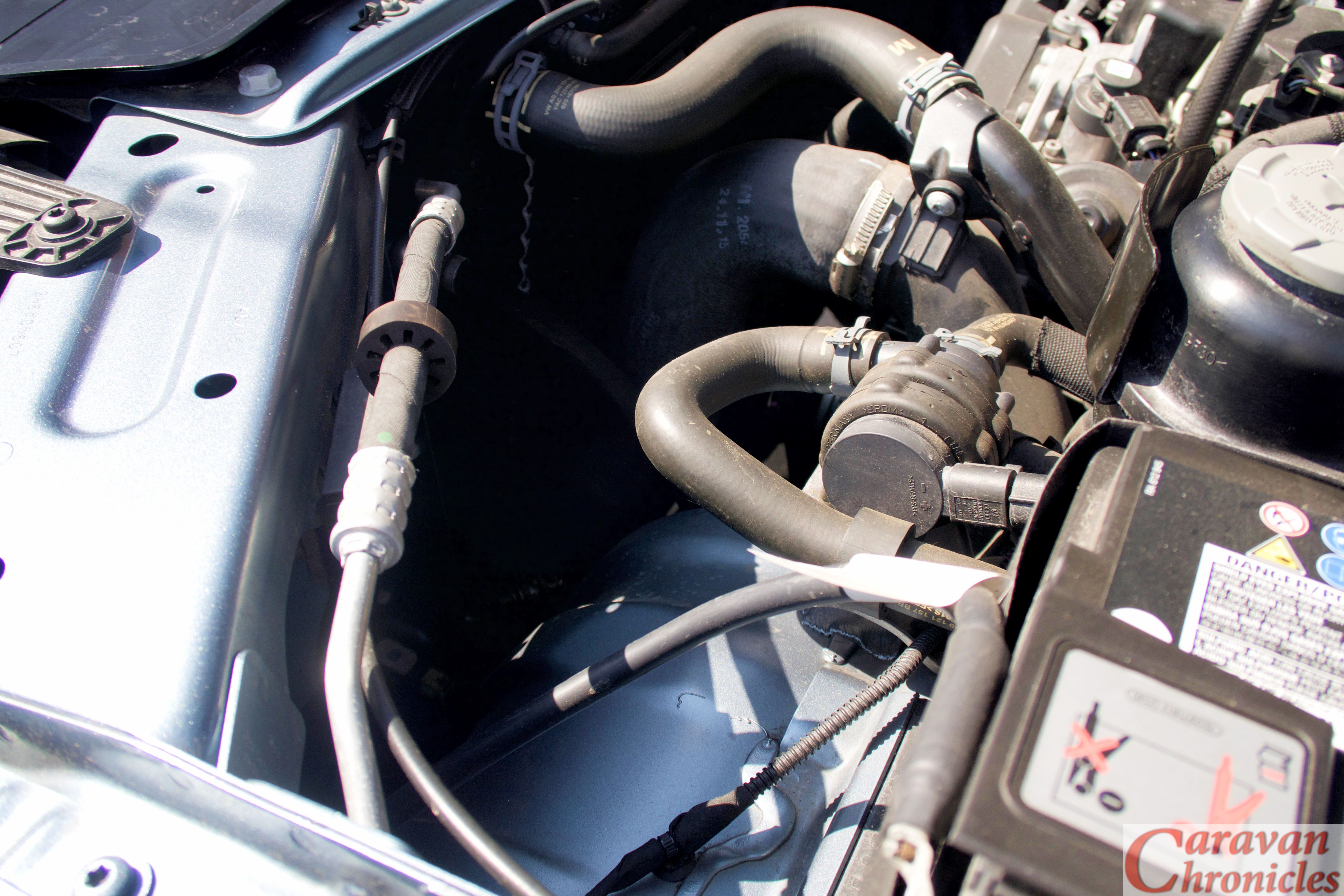
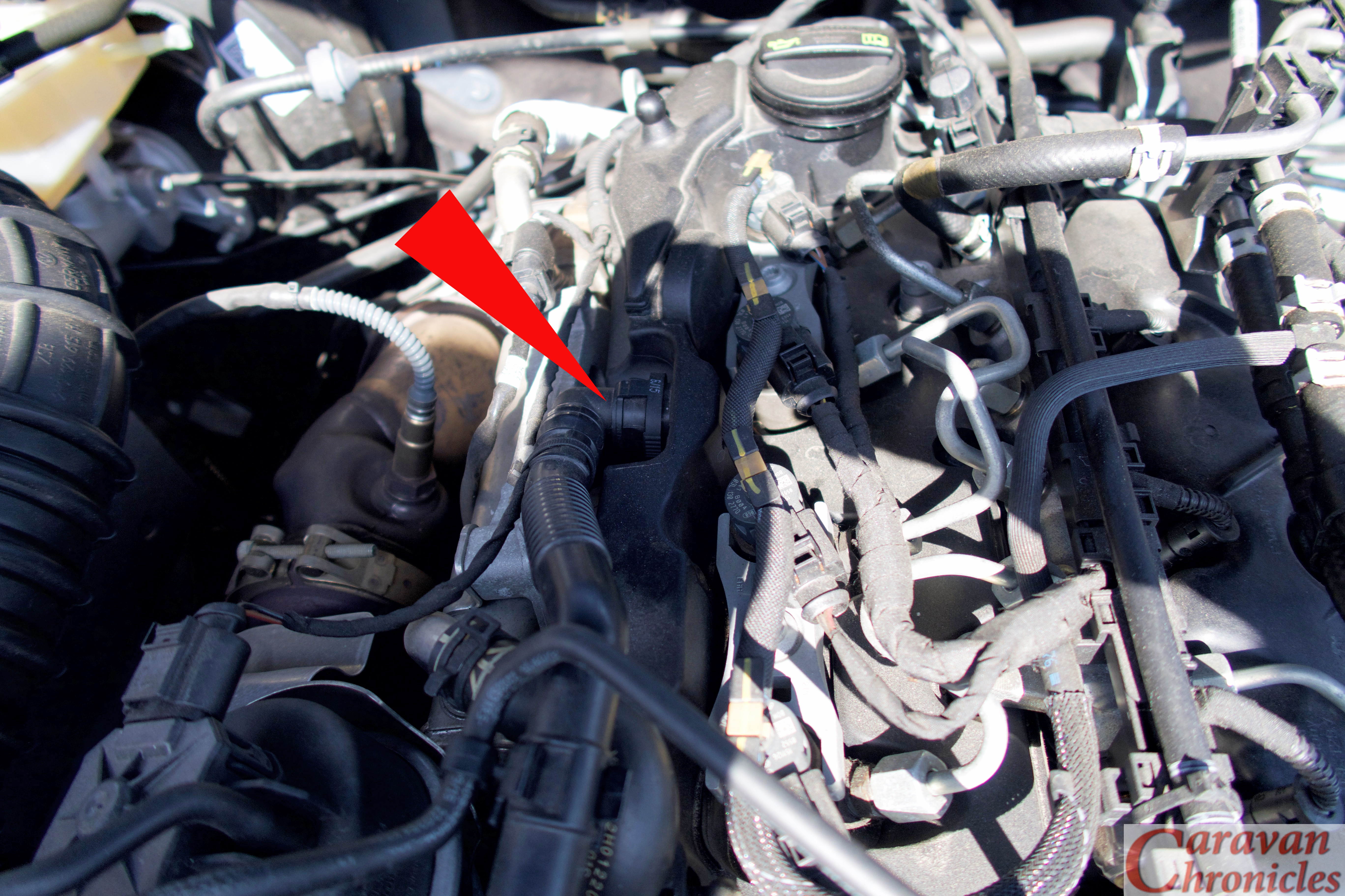
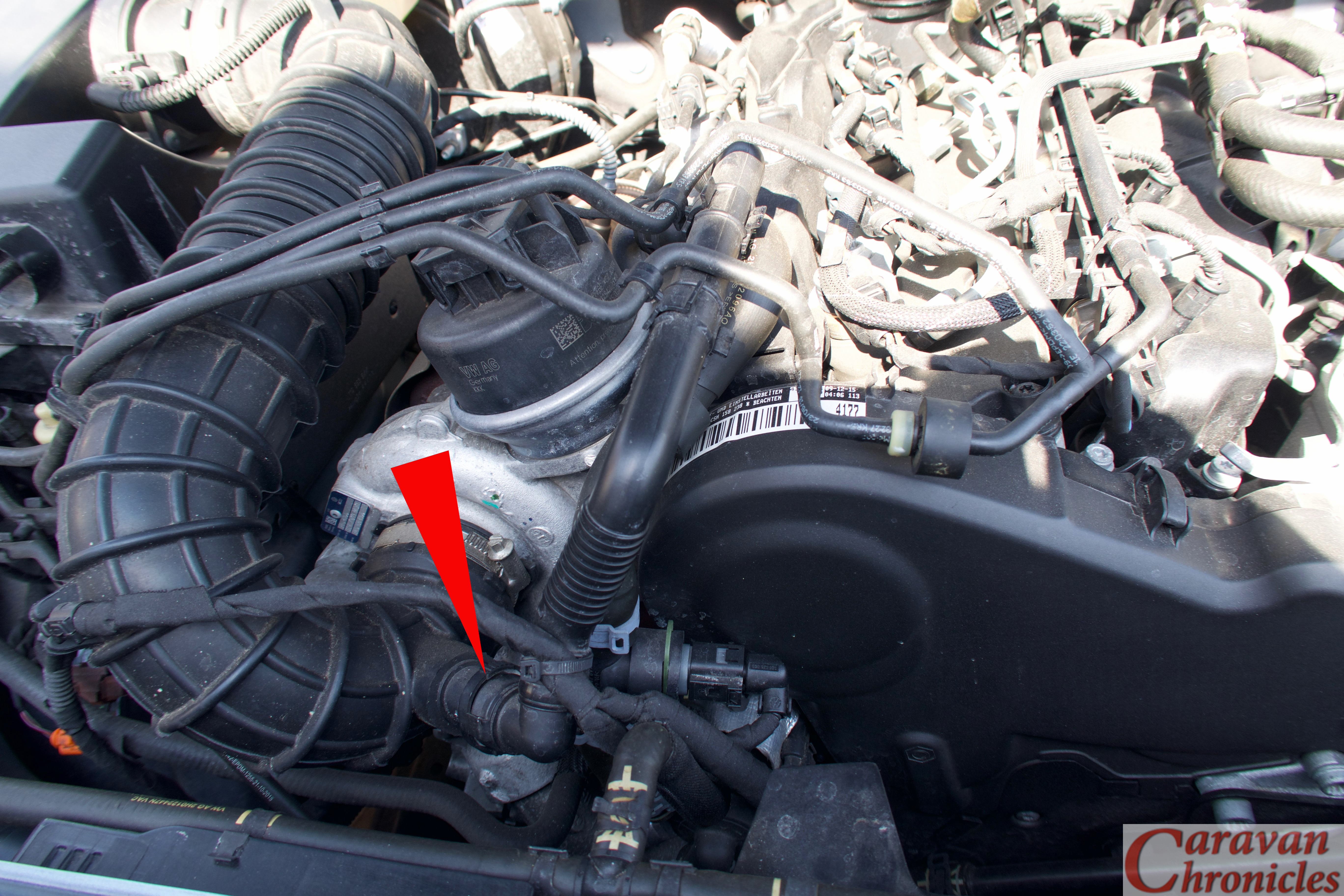
This would also allow the two pipes… one from the crank case pressure release port (left below) and the return to one of the turbo inlet ports (right below) could take a short route from the ProVent across the front of the engine and would give me a couple of suitable points to mount supports for the pipes.
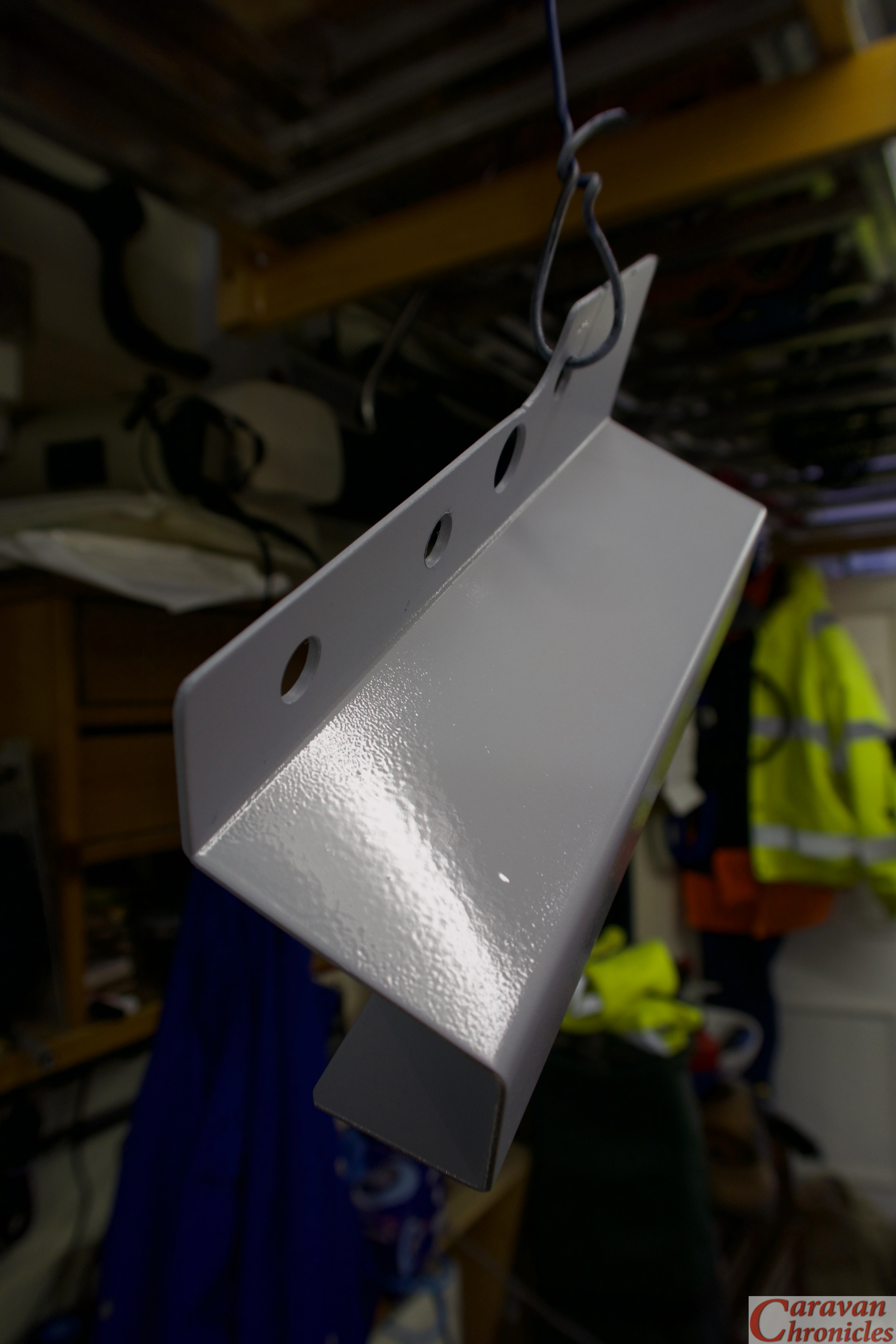
I needed to manufacture a bracket that mounted to the top cross rail and went over the air-con hose and bonnet release cable just below it. As luck would have it in my scrap metal bin I had the chassis from on old bit of electrical kit that was made out of aluminium and looked like it would do the job.
Cutting a section off, filing down the edges and drilling mounting holes didn’t take too long and that was followed up by a coat of etch primer and a couple of coats of high temperature gloss black (I only used that as I had a spare can from a previous job!)
Fitting was fairly easy…. and no, they will not be the final bolts!
Marking and drilling three holes, followed by a couple of coats of metal protector to stop the edges of the holes rusting soon had the bracket in place. If you are wondering why the shape… well it came like that when I cut it off the scrap chassis, but quite by chance it allowed access to the hole which is access to the headlight adjuster screw.
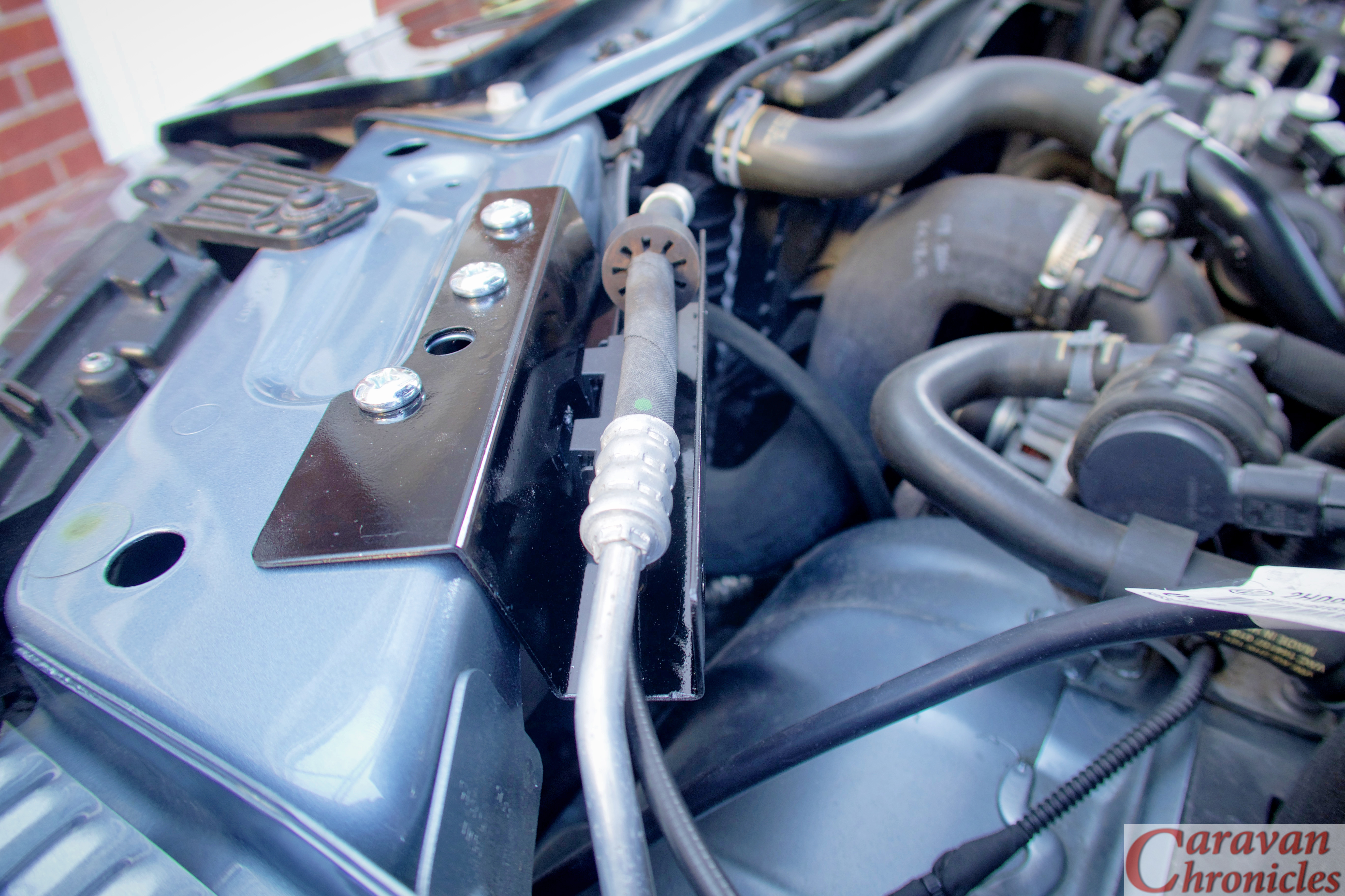
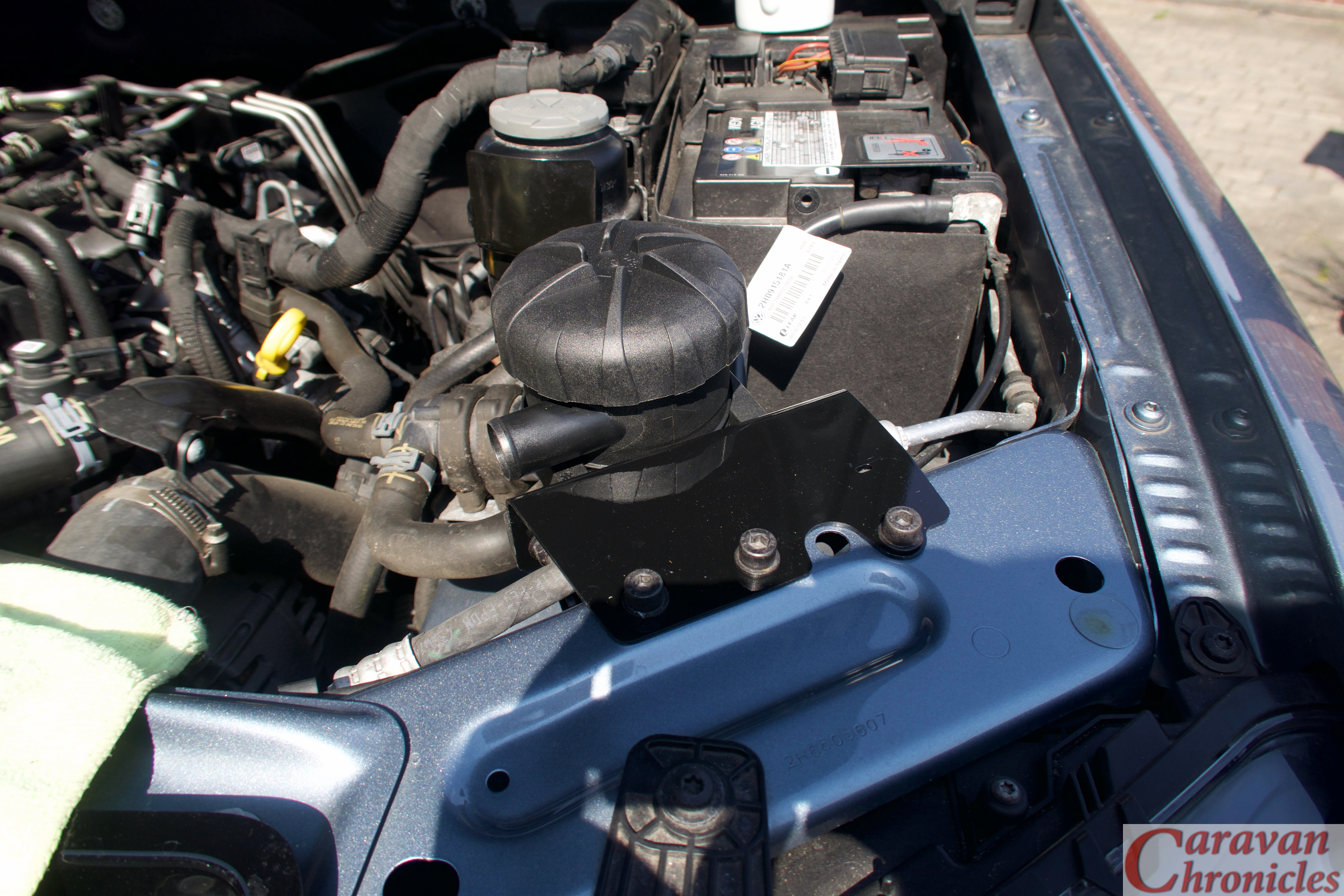
Mounting the ProVent was now simple enough…
It was at this point I stopped. I didn’t like the way it covered the air-con pipe. There was little chance of it rubbing, the pipe already had a big rubber ring on it to stop chafing against the front cross beam or the bonnet release cable. I also now could not get to the bonnet release cable. The mount covered the point where there was a lubrication and connection block for it. It just wasn’t good engineering design. IKB would be shaking his head and wafting his cigar around in dissatisfaction..
Back to the bat cave. Time for a rethink and to hone my skills in sheet metal origami.
I would like to thank Charles at HumbleMechanic.com for all the information and videos he produces about VW vehicles. Charles has been an absolute gold mine of information for all things VW and if you drive any of VW’s vehicles please be sure to drop in on his YouTube channel and take a look.
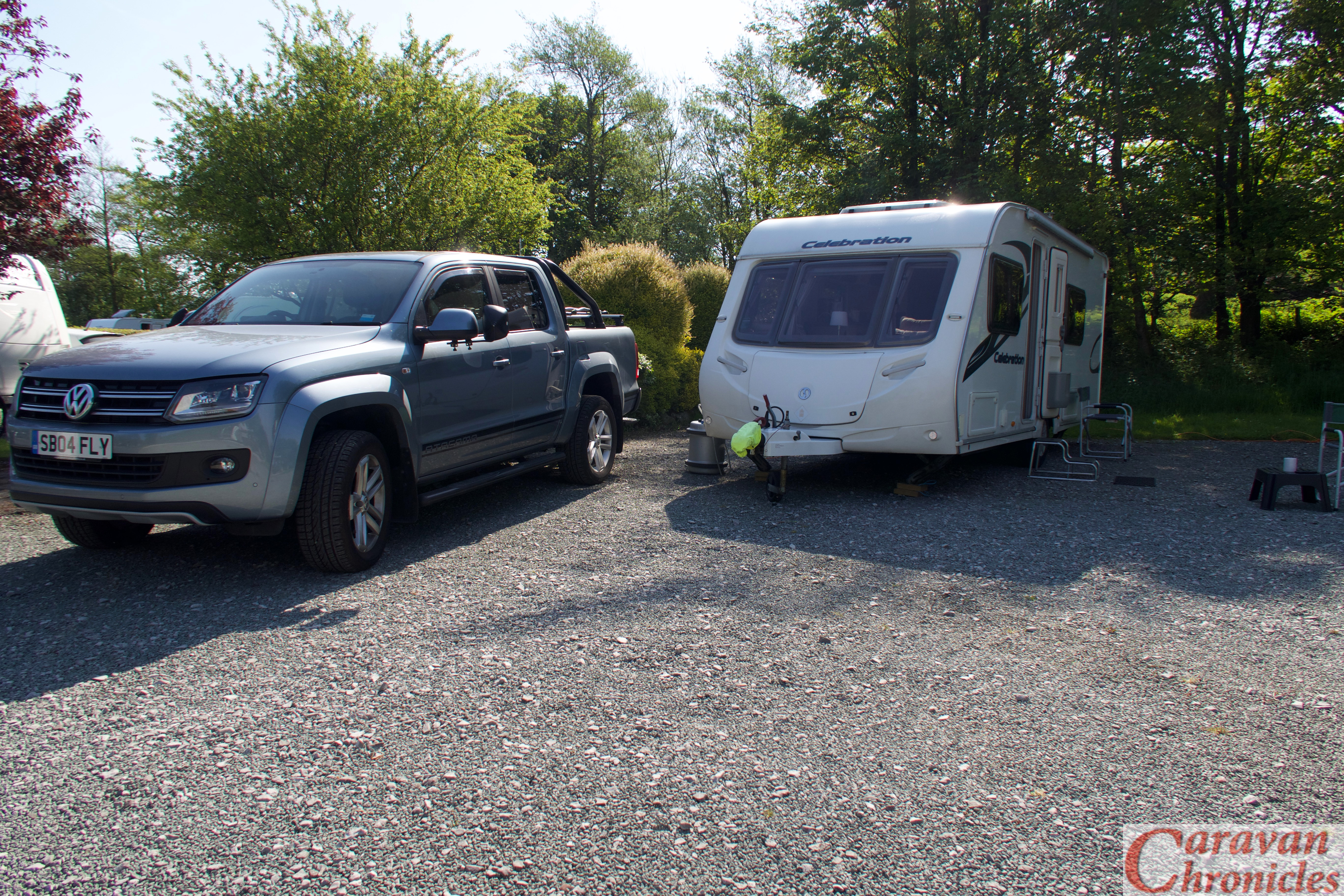
A few weeks ago Andy Harris (yes that Andy… him off the TV) and of Road Pro fame called me to tell me about a new gadget that Dutch caravanners were getting all excited about. Now not one to turn down the chance to test a gadget or two, when Andy asked if I’d like one of the units to test I of course said in true reserved fashion said “Well I suppose I can take a look at it”. Who wouldn’t pass the chance to check out the latest piece of tech gadgetry being made by those clever Dutch people at e-Trailer. A few days later a large brown box arrived.
On a recent trip to the C & M Club’s site at Blackshaw Moore I took the opportunity to not only put my feet up for a couple of days with Sue but install and play around… er… seriously test… one of the units..
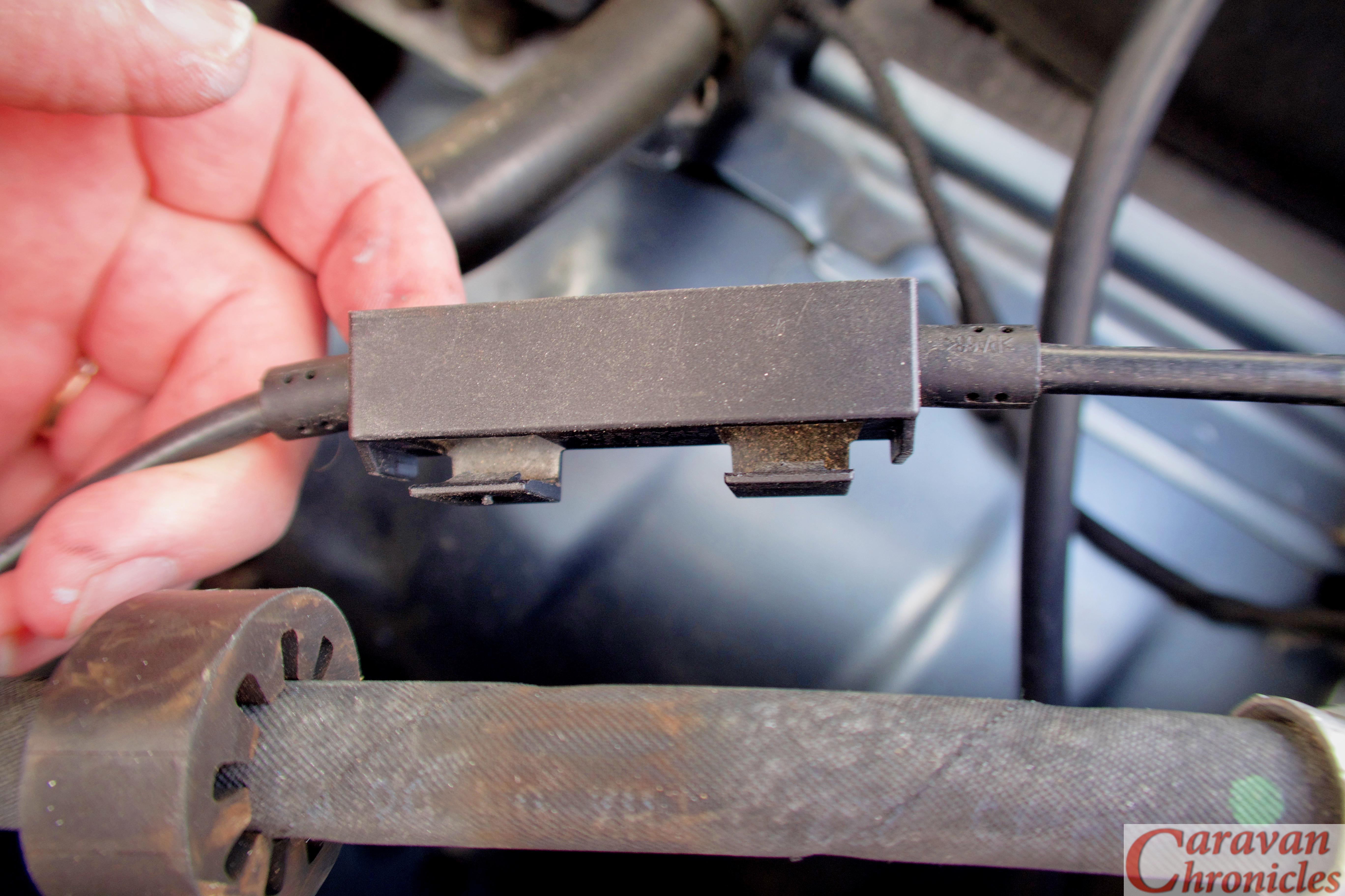
Opening up the box I found five smaller boxes, containing the main unit and four of the modules.
Ok, so what is e-Trailer? The simple explanation is there is a black box that sends all kinds of information about your caravan to an app on your phone. It works with both Android and iPhones and there are various ‘modules’ you can add-on to get additional info.
The actual unit is about 120mm long by 80mm wide and 40mm high with a good quality power connector at one end.
In the box is the main unit, 1.5 metre long power lead, instruction manual and a card with a QR Code on it.
You get a QR code with each of the modules, and set of instructions, don’t lose the cars with the QR codes on them! (more about these later)
Installing the unit is serious easy. You just hook up the power lead to a 12 volt supply. I opted to connected to a switched supply sort came on whenever the caravan master switch was on. This would mean it would be active when towing.
Once you have powered up the main unit, go to the website e-trailer.nl/app and follow the link for your phone. In the case of my iPhone it took me to the App Store were I could download the app. Once downloaded launch the app and follow the on-screen instructions to register. I was a bit surprised it asked for my postcode and house number, but I guess this is how they register the unit to you for warranty etc.
Once you have created your account in the app and logged in… well remember that card with the QR code on it, simply scan the code and it pairs the app with the unit you have just installed.
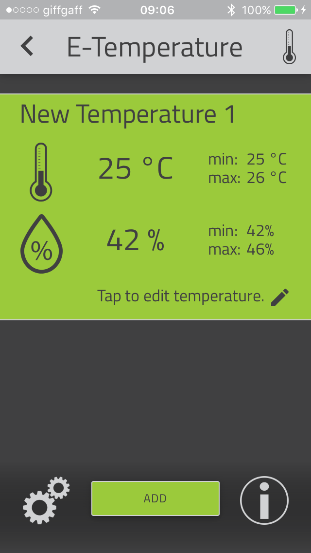
You are done! It’s that easy. Now to add the modules. The first one I added was the temperature module. You get a small puck shaped device and following the on-screen prompt, scanned the QR code.
Done… a quick scan and now I have the temperature reading. For each module you can set lower and upper limits and the type of alarm… visual notification, vibrate, sound. From reading the instructions you could put this sensor in the fridge so when you are driving along you can keep an eye on the fridge temperature to make sure your wine or beer is perfectly chilled when you arrive. From what I understand you can add additional temperature sensors so you can check what the temperature is in the caravan at the same time.
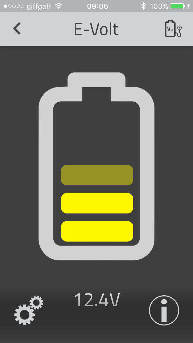
Next was the voltage sensor so you can keep an eye on the battery voltage. Again it was a quick scan of the QR code and I could see instantly what the battery voltage is and its relative state of charge. (I have yet to check how accurate this is).
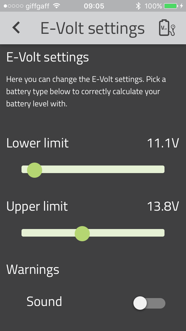
Again, it is easy to set the limits, just tap the two cogs in the bottom left corner….
… And you can adjust the upper and lower alarm voltages. This is really useful as you can correctly set it for flooded call, AGM or lithium batteries.
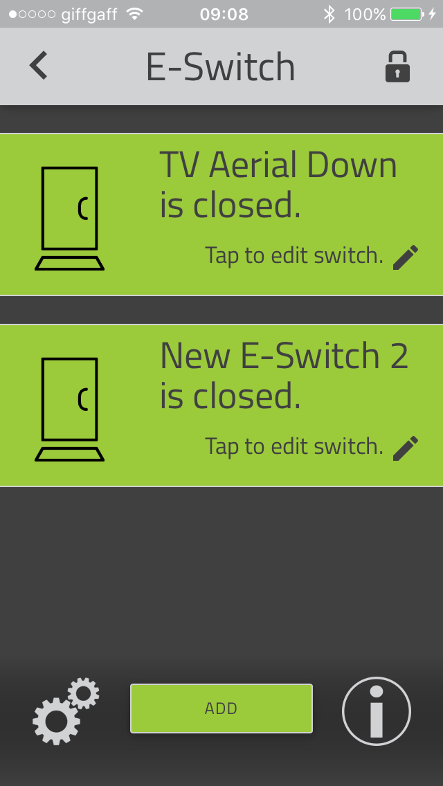
Want to know if you have left your roof light open or TV aerial up… or even if your fridge door is open? There’s a module for that… The E Switch.
In the E-switch module you get two magnetic contact switches that come with 3M pads so you can stick them almost anywhere. Again adding them is a simple scan of the QR code and follow the instructions on-screen. I edited the text for the first switch so I know it is the TV Aerial.
If one of the switches is open, on the home screen you see that the padlock is orange, close the switch and the padlock closes and the icon turns green.
So what else can it do? Well I also have the tyre pressure monitor module. You get two pressure sensors to attach to the tyre valve stems. The sensors are the type that you can change the battery, which I much prefer, as opposed to the sealed type. I’ve not installed the TPMS module yet as I’m still testing out other TPMS systems on the Amarok and caravan but no doubt it will be an easy install… by just scanning the QR code!
The last little trick that is has is it is an extreme accurate caravan levelling aid. Again a quick scan of the QR code gets this up and running and follow the on-screen instructions to determine your level point and it becomes easy to level next time you pitch.
OK so what did I think about it?
Well it was super easy to install. It was also super easy to add each module. I like the fact that when you hit up to set off you can check the battery voltage and see if it is charging. You can make sure what ever you have attached the magnetic contacts to you can see if they are in the correct position (i.e. closed, lowered etc.) and you can check the fridge or caravan temperature and tyre pressure.
While driving you can keep an eye on things like your caravan’s tyres, battery charge and fridge temperature. when you arrive on site, reversing into your pitch you can easily see if the caravan needs levelling side to side using ramps or blocks and when you un-hitch you can adjust the jockey wheel to get perfect levelling front to back.
“We have a problem Huston…..”
Now I do have a problem with it. Come what may I cannot get it to vibrate, notify me or play a sound when anything goes out of the parameters (switch open, battery voltage low etc. I made sure I had the latest version of the app, I have double checked all the settings within my iPhone but I cannot get a single ‘vurrrrrr’ or ‘ding’ out of it. Admittedly my iPhone is now 2 versions behind the times but if the app installed I’d have expected it to work ok. I’ll continue to work on this one.
Finally…
I think the idea and technology is great behind the product and I really do like it and can see lots of additional applications could be added on in the future.
Why though is it an after market accessory? When you can be paying the best part of £30k for a top end caravan should not this sort of information system be standard? When I hitch up and set off, I’d love to be able to check the battery voltage (and charging current) check the fridge was working, tyre pressures, doors and hatches closed… and it is not beyond the engineering skills of man to be able to have a bulb out detection system for the road lights even…. all fed directly to your phone.
If a manufacturer decided to install such a unit the price point would drop dramatically.. and that’s one of my other niggles. The technology and ease of installation is great, however there is a bit of an ‘ouch’ in the wallet as currently the comfort pack is priced around £380. That’s a lot of nights on site. You can build up the unit by just buying the individual modules though.
Do I want one… “Yes”…. would I buy one…. I’ll just go and have a word with Sue.
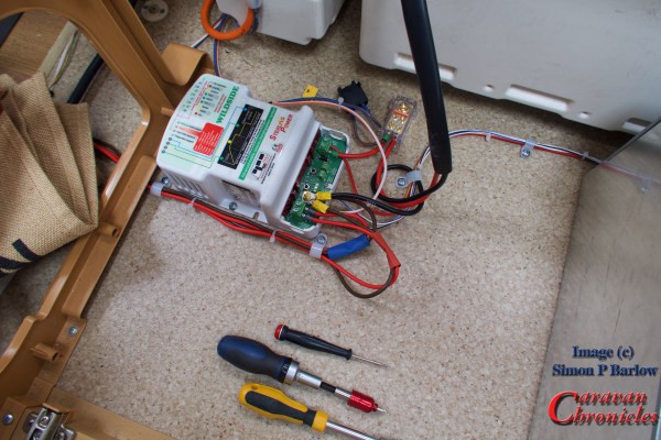
I guess this really is the update to an update (Getting All Charged Up – Update…). We have been living with the Sterling Wildside unit now for about 6 months and a LOT of people have been emailing me asking how we are getting on with it and is it worth it?
Well I have done quite a bit of testing with my leisure battery in various states of discharge. With it at about 50% I have recorded a charging current of 15.9 Amps which is far greater than I could manage before and due to the fact that the Wildside unit uses the correct charging profile for my battery I’m not concerned that I will be reducing or damaging my leisure batteries life expectancy.
Earlier this month I had an email from David Dent who had successfully installed a Wildside unit in his Bailey Unicorn 3 Cadiz and he seemed pleased with the results so far. Although installing it in a Bailey was a bit more of a challenge. I’m looking forward to checking back with David to see how he is getting on with his unit.
A couple of other people have also emailed me reporting that after installing a Wildside unit that it had solved their problem of having enough stored energy to operate their motor movers. I still wonder if people who have been experiencing problems with their motor movers caused by supposedly bad batteries and have had to replace them is possibly down to the fact their battery was never really receiving a correct or full charge before causing its early demise.
New Tool…
One of the things I want to get to add to my ‘tool box’ in the near future is one of the computerised digital battery testers. At the moment I’m basing a lot of my work on the voltage of the battery and chemistry type. I’d like to be able to improve on this.
Watch This Space…
The other thing I’d also like to be able to do is get a voltage and charge current reading for the leisure battery while we are actually driving. I have been looking at a few – mainly American options for bluetooth remote voltage and current sensors that you can connect up to with your phone. There are a couple of devices that offer a separate display to fit in your vehicle.
However, there is a rather exciting unit that will shortly be coming on the market in this area that might be a bit of a game changer. If you want to know what it is well go and see Andy Harris or one of the guys on the Road Pro stand at the NEC in a couple of weeks time as they, along with the manufacturer will be launching and demonstrating a new product that might just be bringing caravan technology bang up-to-date. I hope to be bringing you a bit more about this soon and maybe an install too!
Final Thoughts….
Is the Wildside unit worth it? Before I answer this let me just say I am not being paid by anyone for any endorsements of this unit. I was supplied one of the first (pre production?) units as a test and to provide feedback to Sterling Power on how easy it was to install and it’s performance in the real world, which I did. As a result a couple of things were ‘tweaked’ hence mine had to be returned, reprogrammed and reinstalled.
Well I’d say if you have a Euro 6 or even a 5 engine and you want to make sure your battery is looked after then yes. If you want to upgrade to a more advanced battery chemistry, again yes. If I had to return mine would I go out and buy one? Yes I would.
Is there anything I’d like to see changed? Well if they ever did a Wildside 2.0 I’d like to be able to move the caravan’s own charging system so it was routed through the Wildside unit when on mains hook up to take advantage of the Wildside’s smart charging facility and to allow you to move to more advanced battery chemistry. I guess also adding a solar panel input with built-in MPPT would be a big hit too.
In The Future…
I’m starting to wonder if the way we charge and power caravans needs to take a leap forward. I have had an idea that you could basically split an inverter. One half in the vehicle and the other in the caravan. Imagine a small unit that takes the 12 volt DC from the vehicle and inverts it to 48 volts AC. You then have a lead that connects this across to the caravan and there it is converted back into 12 volts DC.
So whats the difference… all you are doing is what’s already happening? Well using a 2.5 mm cable rated for 25 amps at 48 volts gives you 1200 watts of power. To transfer that much power at 12 volts you would need 100 Amps. Keeping it at 48 volts will mean the system is still in the ELV range for safety. (Use 4mm cable and this could be 1680 watts of power which would be equivalent to 140 Amps at 12 volts)
Being able to transfer that sort of energy would allow you to forget LPG cylinders and put 1000 Ah of lithium cells in the caravan with a 240 volt inverter and power everything. Just a thought that I’m throwing out there.
OK, so if you read about the bike rack install I guess you might have seen the video of me getting onto the tailgate of the VW Amarok…. akin to a whale wearing a tutu and trying to get on points. I needed something better… well my knees were telling me I better do something about it at least. In the USA, the land of the pickup or Australia the home of the Ute there were plenty of options. The downside was the Amarok has not been released in the USA and shipping charges from Australia are insane. I had to find something closer to home. Doing the usual google searches always ended up with products on sale in different continents so I ended up searching for images that contained the word ‘tailgate’, ‘step’ and ‘Amarok’ and after clicking on various pictures discovered Pegasus 4 x 4 in Bristol. (Note to all the companies out there… spending time correctly tagging and key wording all the photos on your websites pays off!) Continue reading →


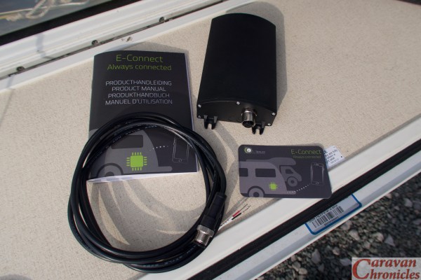 The actual unit is about 120mm long by 80mm wide and 40mm high with a good quality power connector at one end.
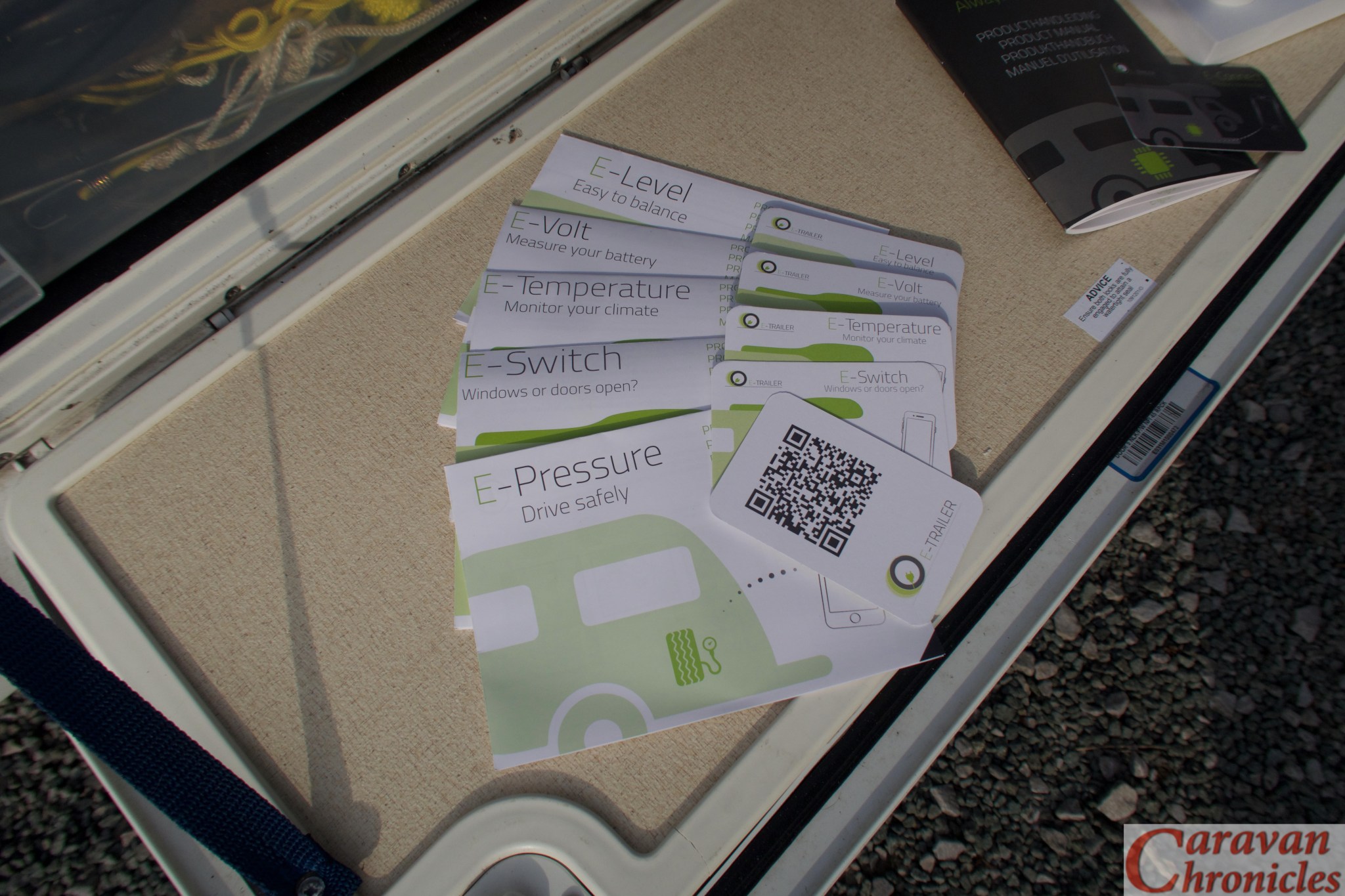


 Well I have done quite a bit of testing with my leisure battery in various states of discharge. With it at about 50% I have recorded a charging current of 15.9 Amps which is far greater than I could manage before and due to the fact that the Wildside unit uses the correct charging profile for my battery I’m not concerned that I will be reducing or damaging my leisure batteries life expectancy.