Tags
“What’s in your toolbox when travelling?”
Tricky one… I don’t have a tool box anymore. I recently started mooching around the internet for a smaller tool box… or rather a tool bag. I used to use up until a few months ago a Stanley Tool Bag. It was lighter than a tool box, I could get more in it… and I could loose more in it too. I had tools at the bottom of that bag I thought I’d lost years ago.
The price of some of the ABS tool boxes, even the small ones took me back a bit. Which prompted the search for alternatives.
As most of my tinkering when out and about seems to be based on electrical, I ditched some of the other stuff…. well really returned a lot back to my workshop. That left me with a selection of tools that I wanted to take. In the workshop most of my tools are Wera, Snap-On, Klein, Knipex, Wiha and Channellock. Not the cheapest brands, but as a lot of my time was spent tinkering with aircraft back in the day, then you soon realise why some tools command a premium price. I still wince at the cost of a set of stainless steel wire wrapping tools for securing aircraft fixings.
So sorting out my ‘portable’ tools I tend to use semi-named brands. Mac do a half decent range of screwdrivers and a small plier and cutter selection. Cheap enough from B & Q (Home Depot) not to have nightmares when finishing something making sure you have picked up all your tools.
The next thing I needed was a bag to store them in. I had a specific size in mind to allow them to fit in one of the lockers of the 5th Wheel… this was to become my “mini- workshop” locker that also housed a box of specific spares for the 5th Wheel.
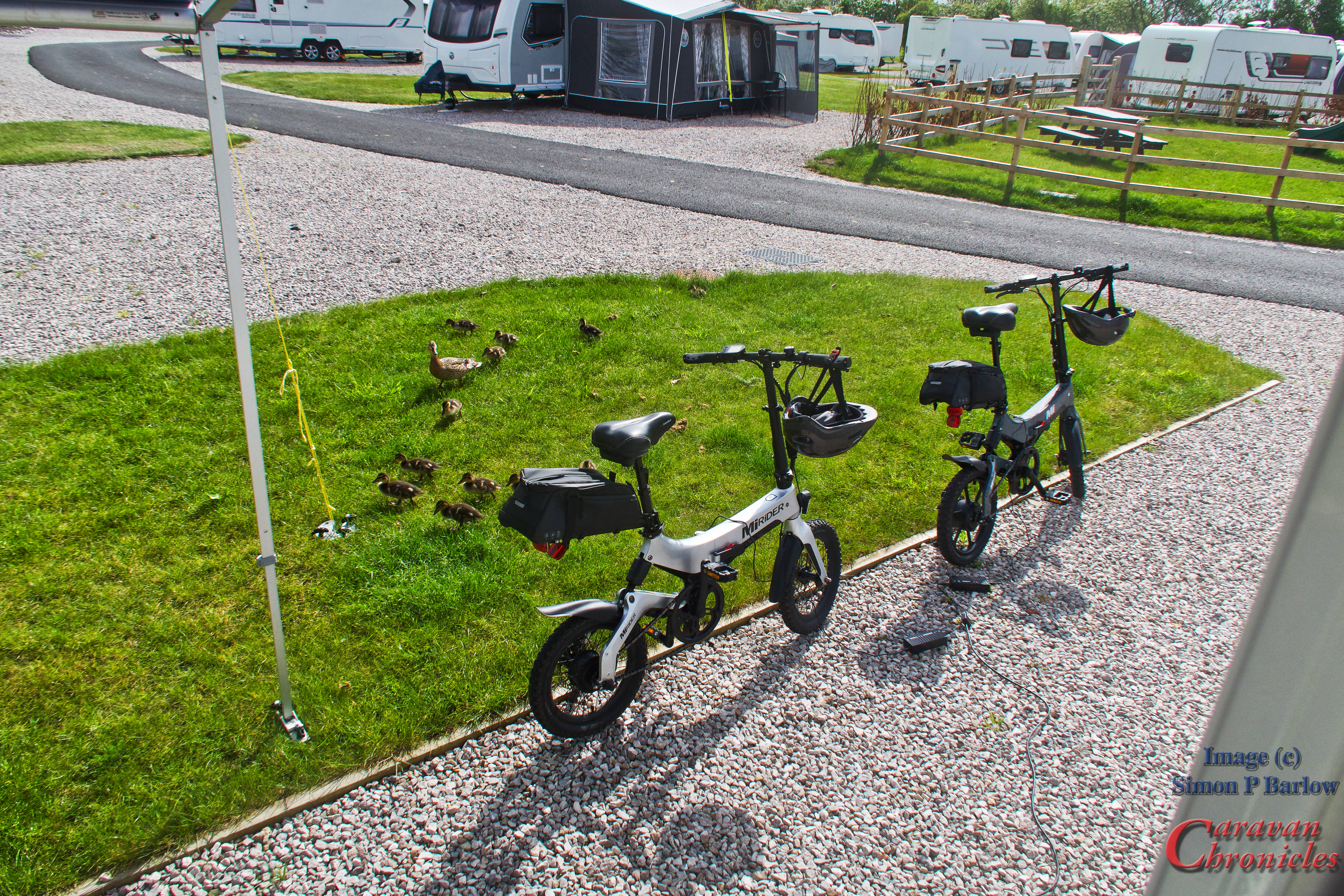
I do have a separate little bag containing tools for the e-bikes that is small enough to drop into one of the bike bags, but that is a bit specific to the MiRider bikes.
Buckets, Bags, Boxes…
I started looking at tool bags, One company bought my eye in the USA… they made tool bags and tool rolls out of old canvas fire hoses. I soon stopped looking when I saw the price… for what they were asking I wanted the fire engine the hose came from as well.
I spotted at the bottom of the Amazon page a company called Ryker. They seemed to offer a bag that was just at the right size and they also had tool rolls and tool pouches. I procrastinated for a few days trawling the web for something that might be better… In the end I didn’t find anything for the same price. Not the cheapest I found but had lots of good reviews.
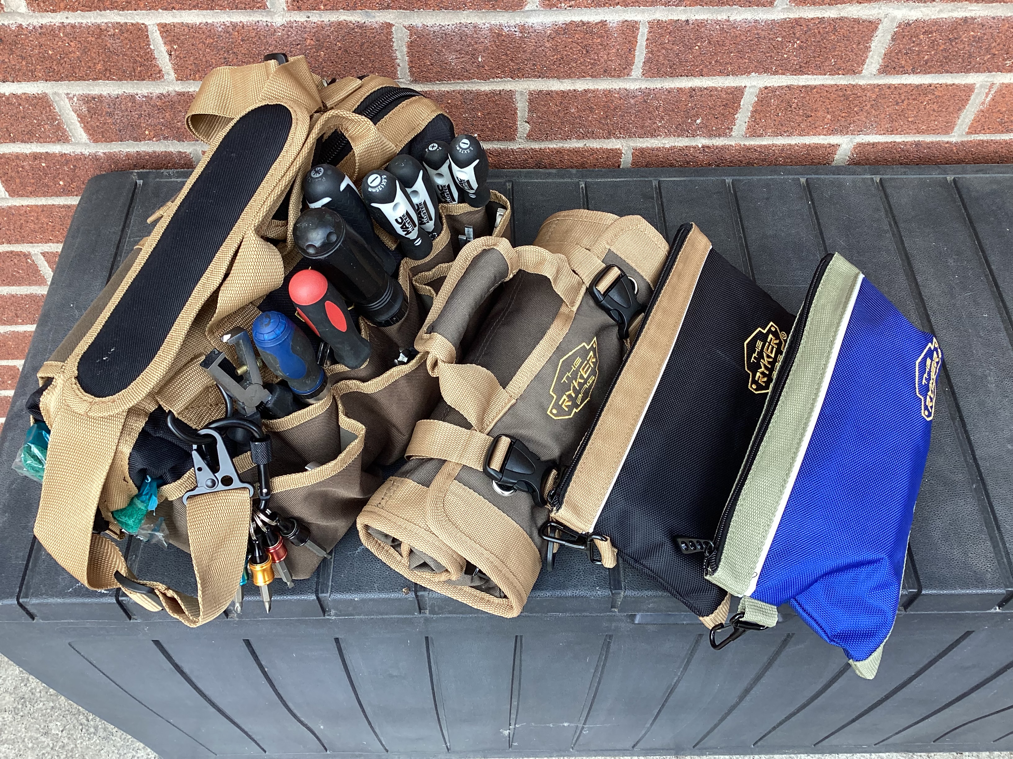
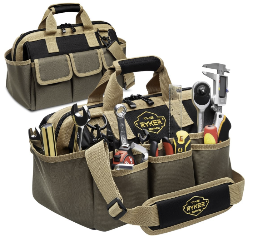
So my portable tool collection is now housed in a small tool bag, small tool roll and two tool zip bags. It all fits in the storage locker on the 5th Wheel or in the tool compartment of the Amarok. It’s all light enough for me to carry it in one hand as well.
Take a Closer Look….
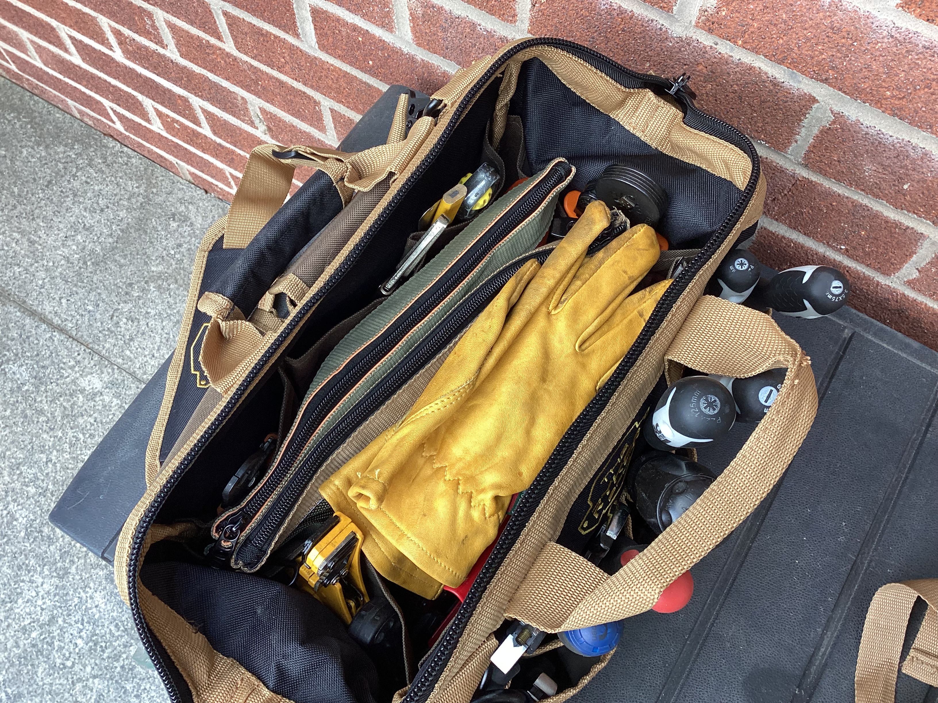
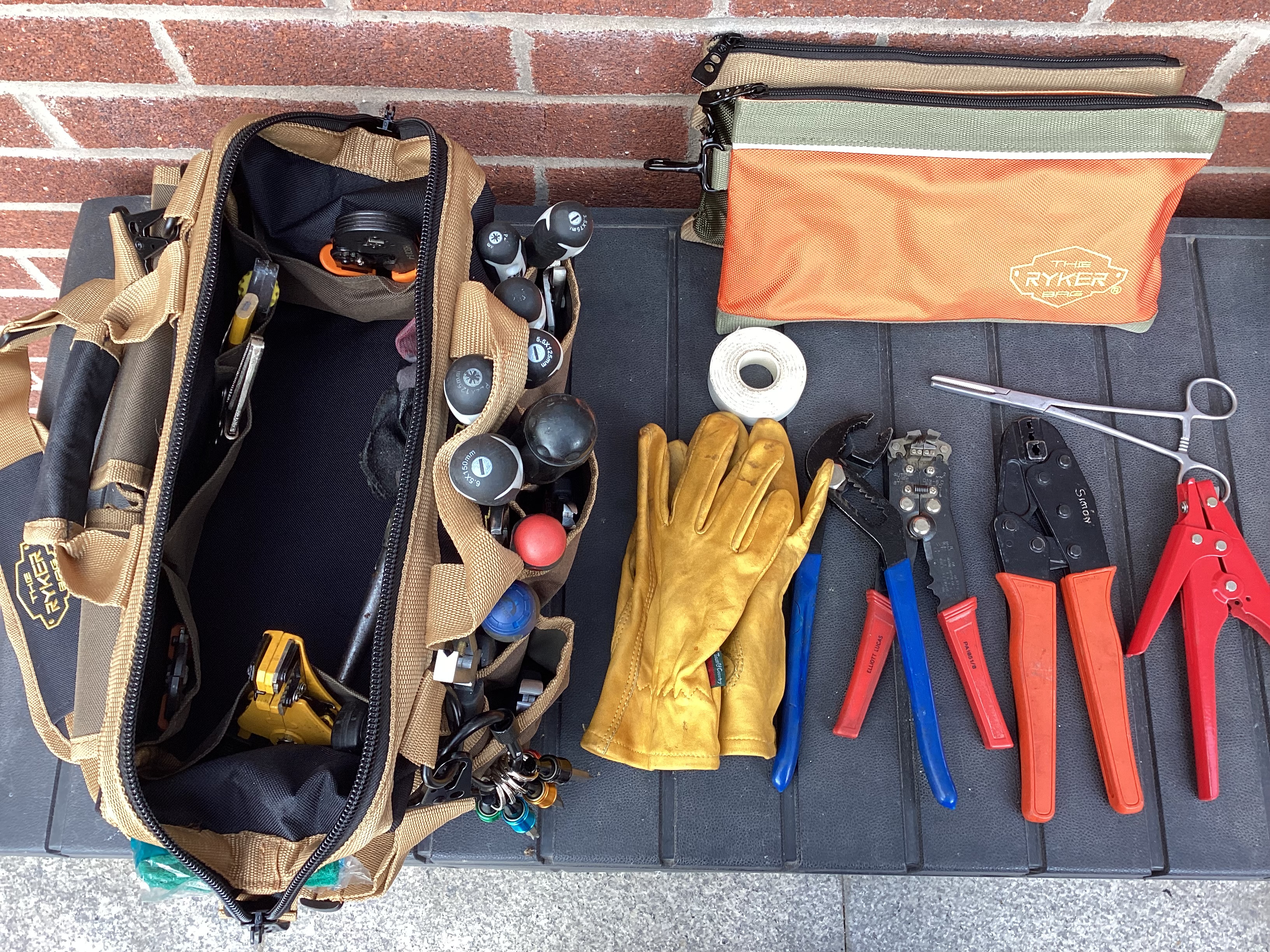
Yep crimp tools are the main thing in my bag… and a couple of types of wire strippers for different cable structures. For automotive use everything should be crimped, never soldered and heat shrunk. I’m still looking for a small portable heat gun (not a gas powered flame type) that can run on rechargeable or 12 volts. I know they are out there somewhere!
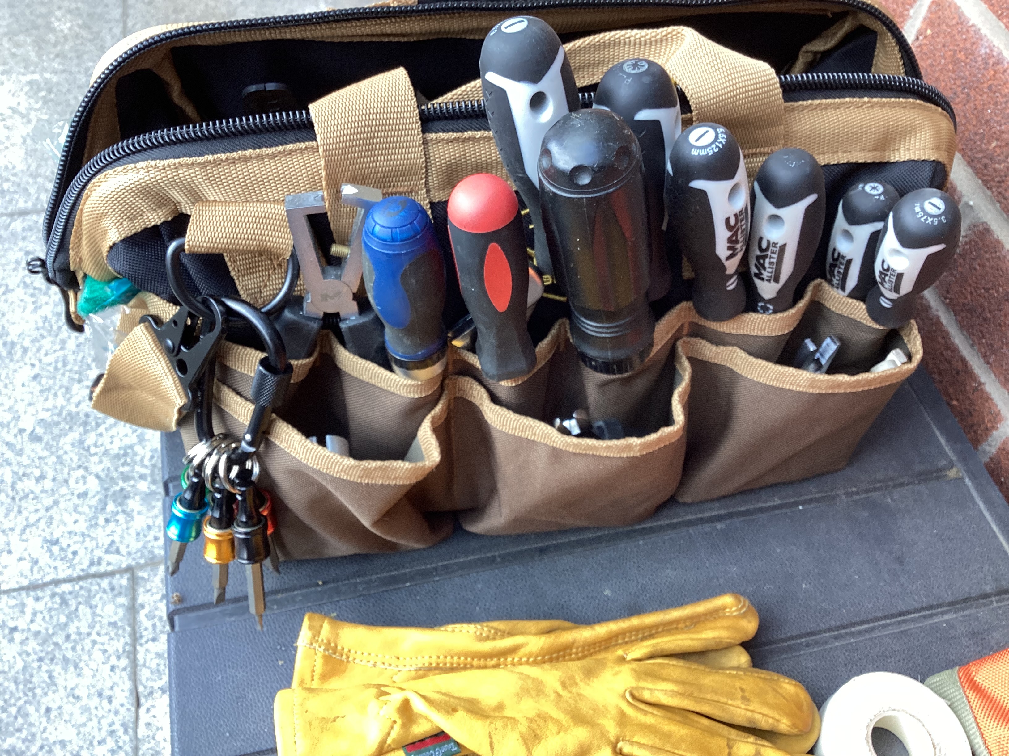
A selection of common screwdrivers along with a torque screwdriver so that terminal screws can be tightened to the required torque and not overdone. (If you have any dealings with Victron equipment, you will know they spec a torque for every connector!)
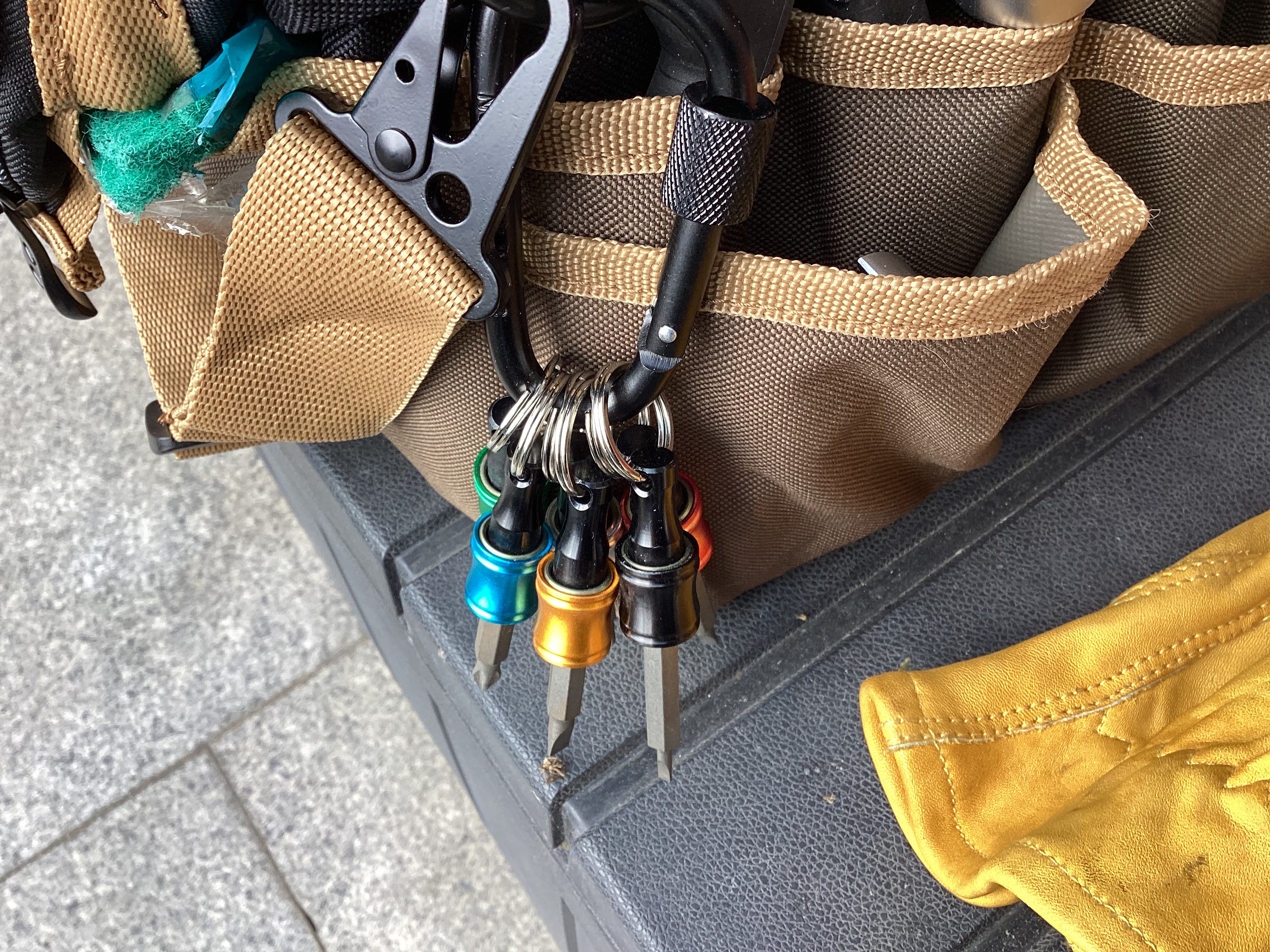
Above: A neat carabina clip containing 7 holders that allow you to easily store the most used hex bits. You can pop them out single hand and return the bit easily after using it. Saves routing round for the correct bit.
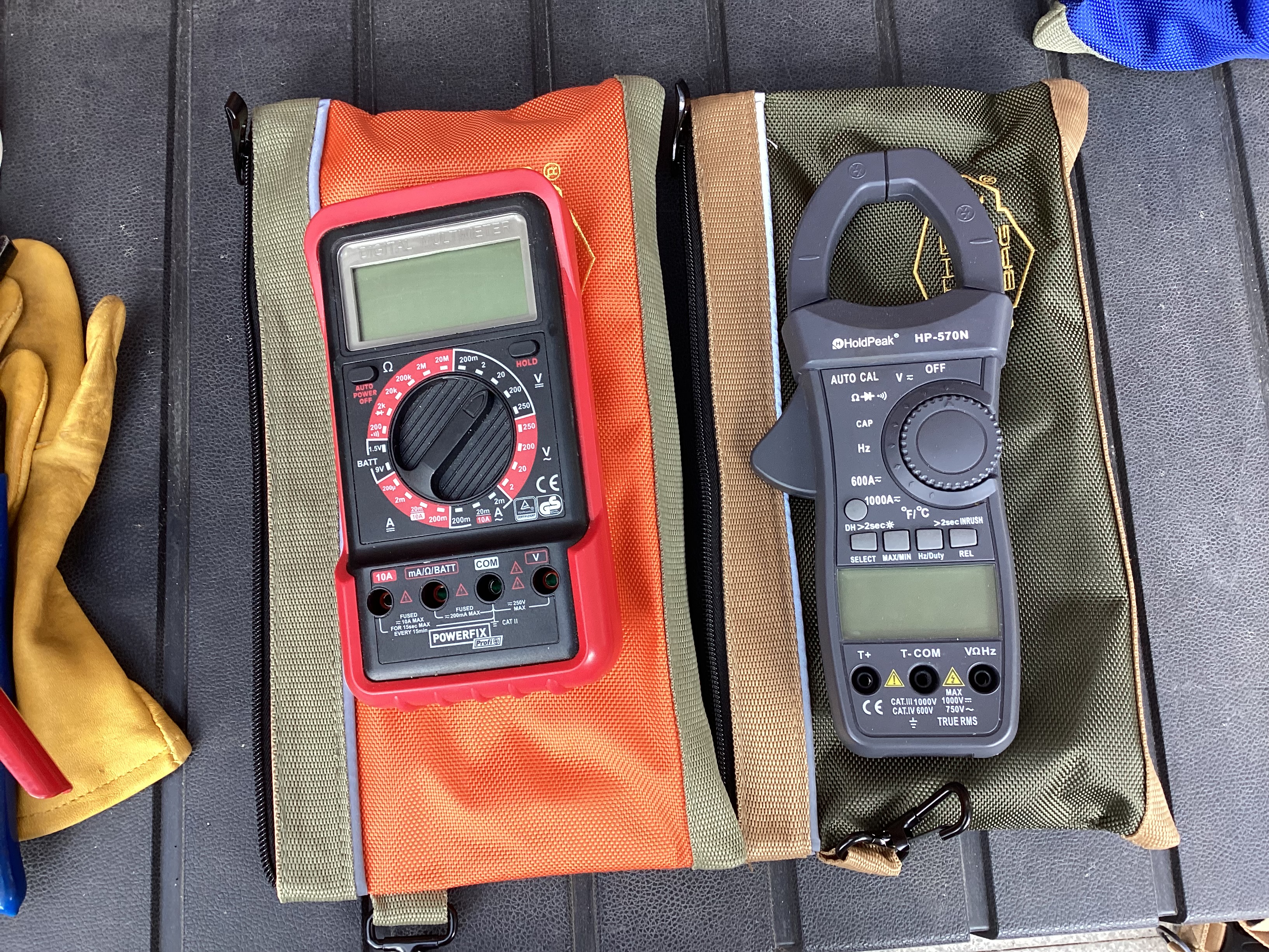
I carry two multimeters, now in their own cases inside the bag. One is a standard fairly cheap all round meter (left) and the other an AC /DC clamp meter that also can double as a general multimeter. Sometime having just one won’t cut it when fault finding. I’m undecided if I should switch out my general multimeter for one of my oscilloscope meters… so I can see CANBUS signals when fault finding. Same size so no storage issues.

If you think I missed out on hex bits…. well there is a full set in one of the tool bag pockets.
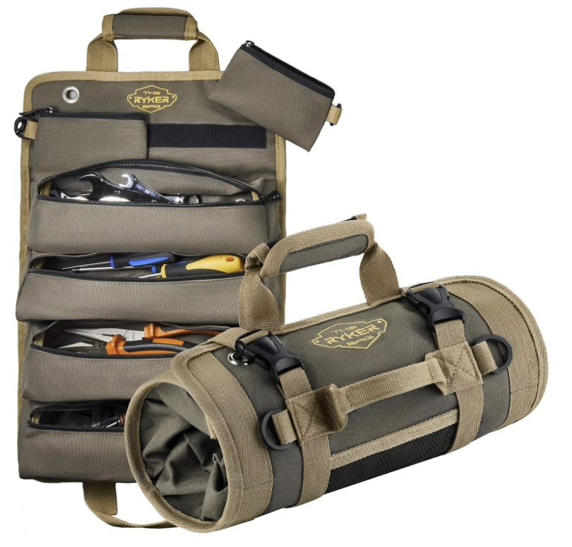
Let’s Roll With It…
OK this is still a work in progress… The Tool Roll.

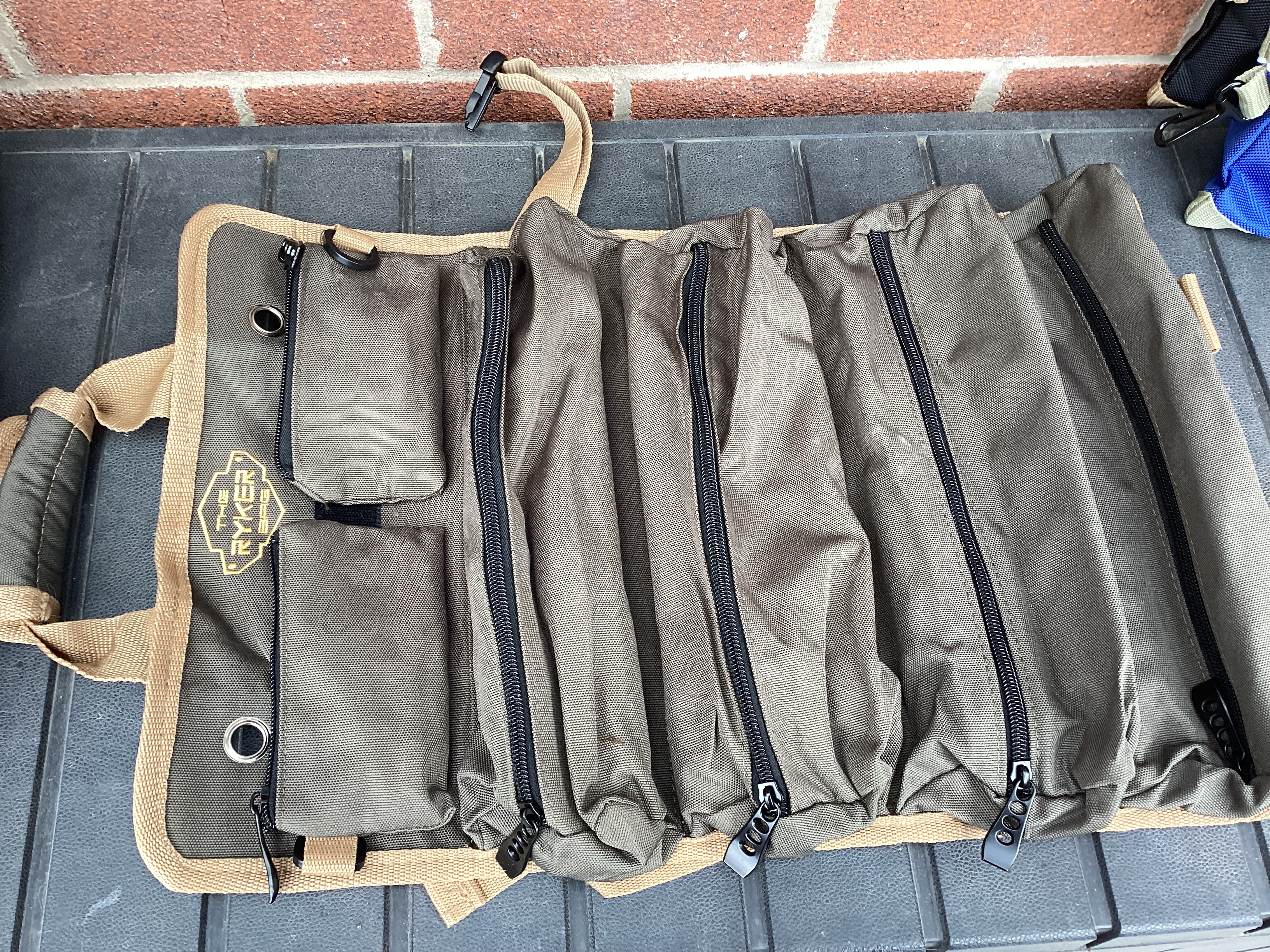
Handy little roll actually. You can hang it up on the wall, it has a couple of removable pouches held in by velcro and a few clips to allow additional tool pouches to be added.
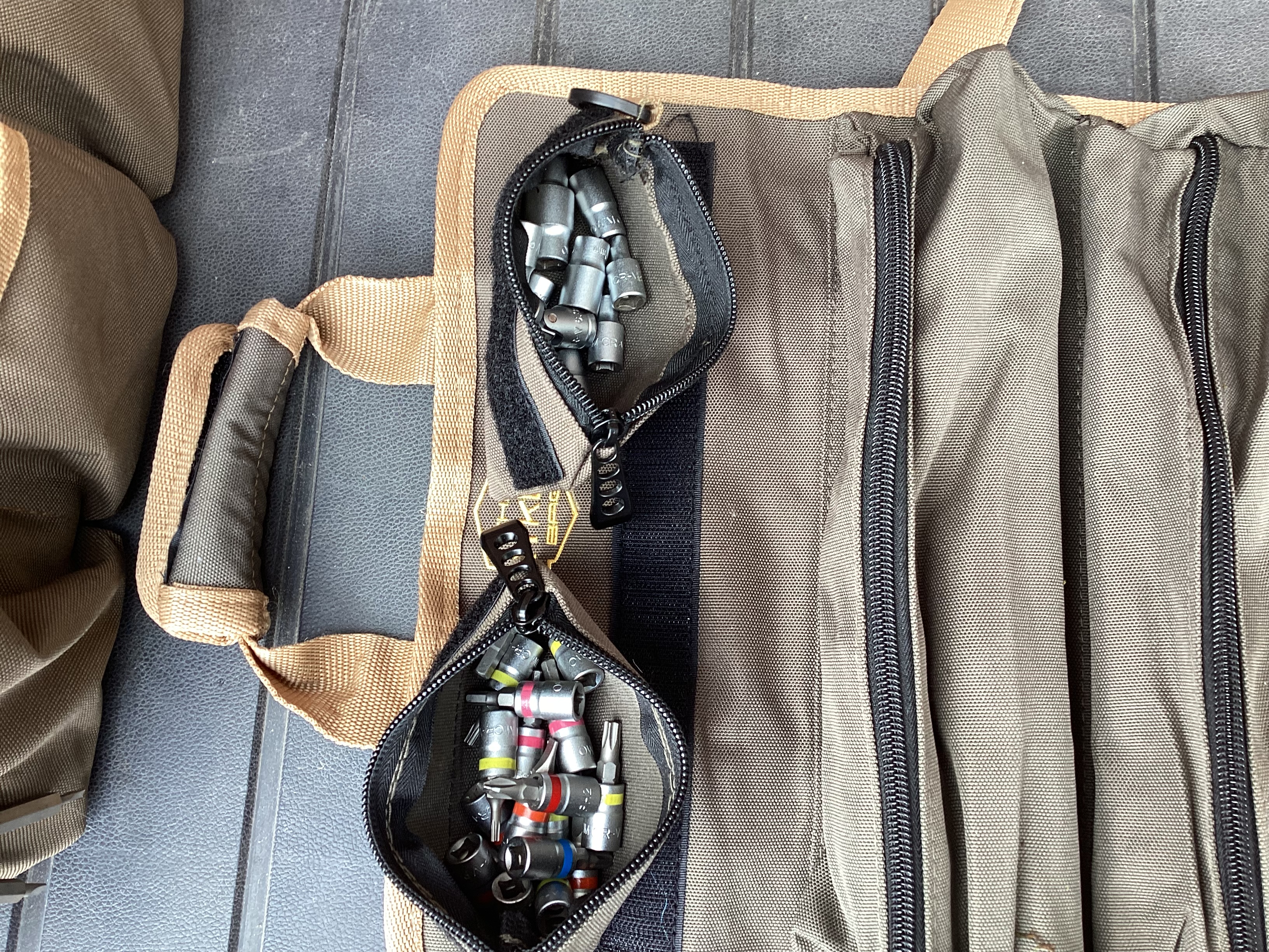
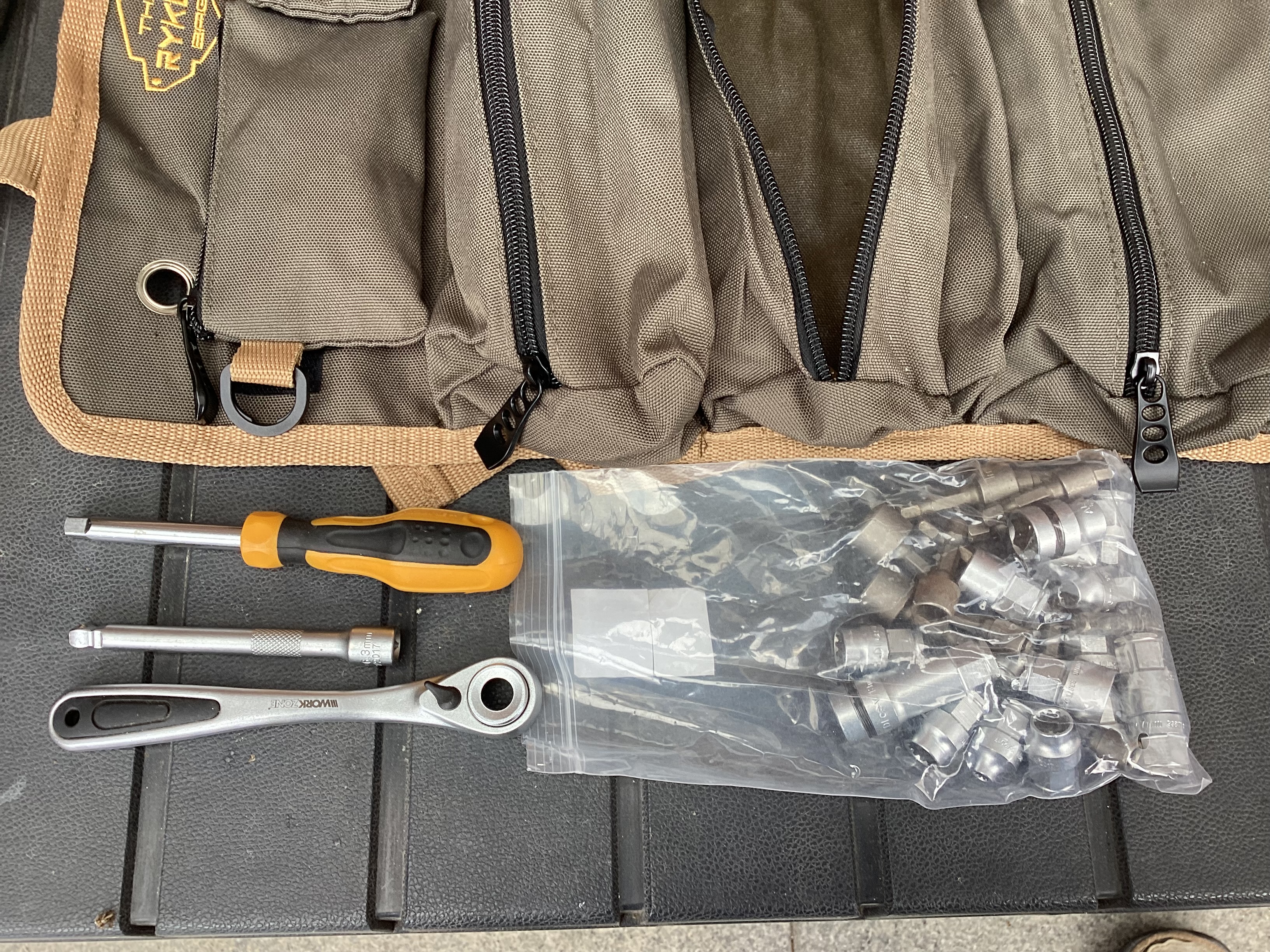
I used them to store 1/4 inch drive sockets and bits. The handles are stored in the first and second main pouches. Along with a 1/4 inch drive torque wrench that allows me to correctly tighten up larger terminals, including lithium battery terminals. My torque screwdriver is only rated up to 12Nm. I also have three 1/4 inch thumb wheels for hex bits for those hard to reach little places.
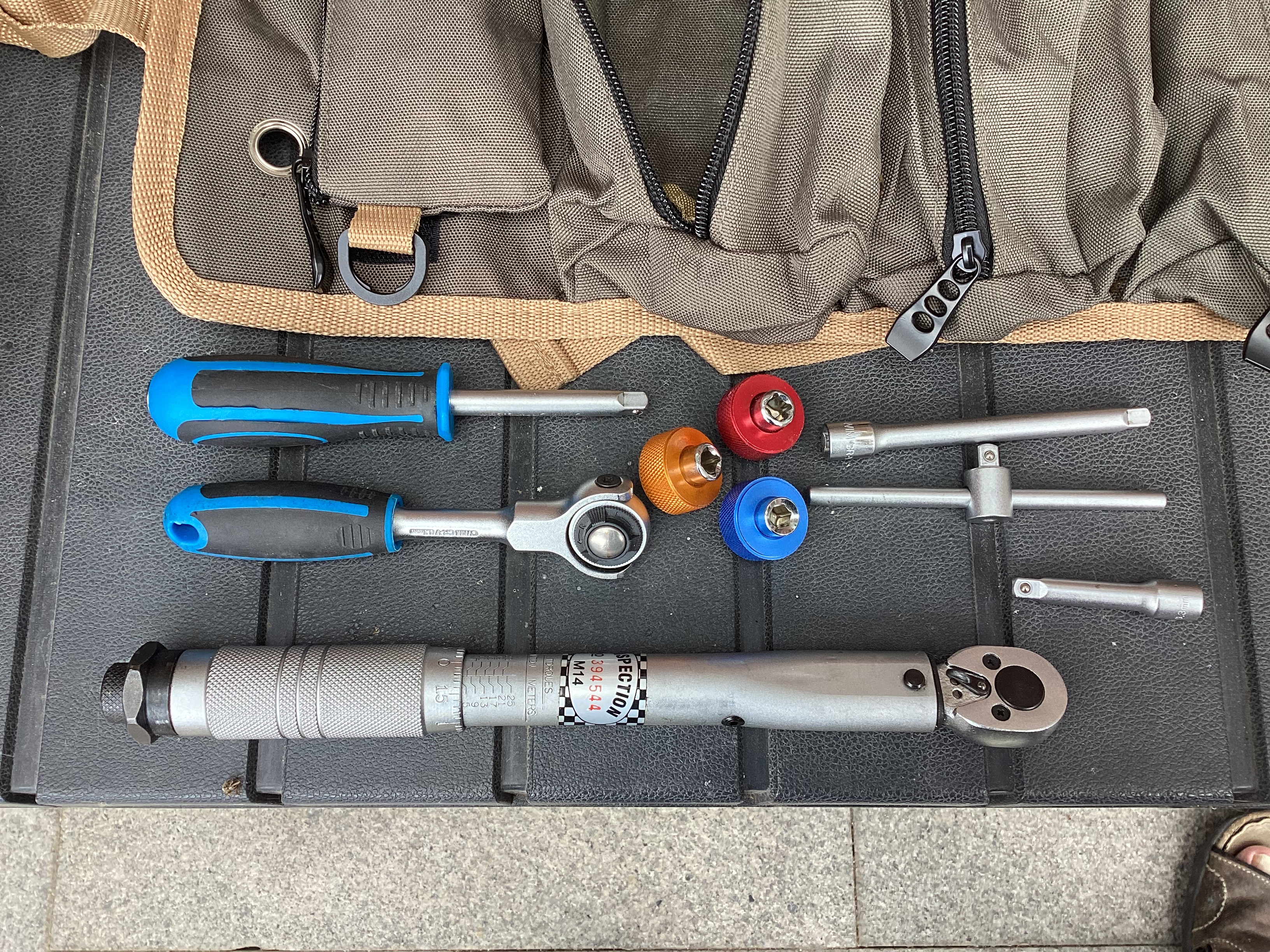
Next compartment is the long reach sockets. These allow you to slip on a socket and ratchet onto a long thread terminal or threaded rod. If you recognise the two sets…. the one above with blue handles and the long reach sockets……. they are Aldi / Lidl specials… each set was cheap as chips and if you look closely they are made by the same company that makes specialist tools for one of the major German tool companies. I recon buying these saved me about £120 over the named brand.
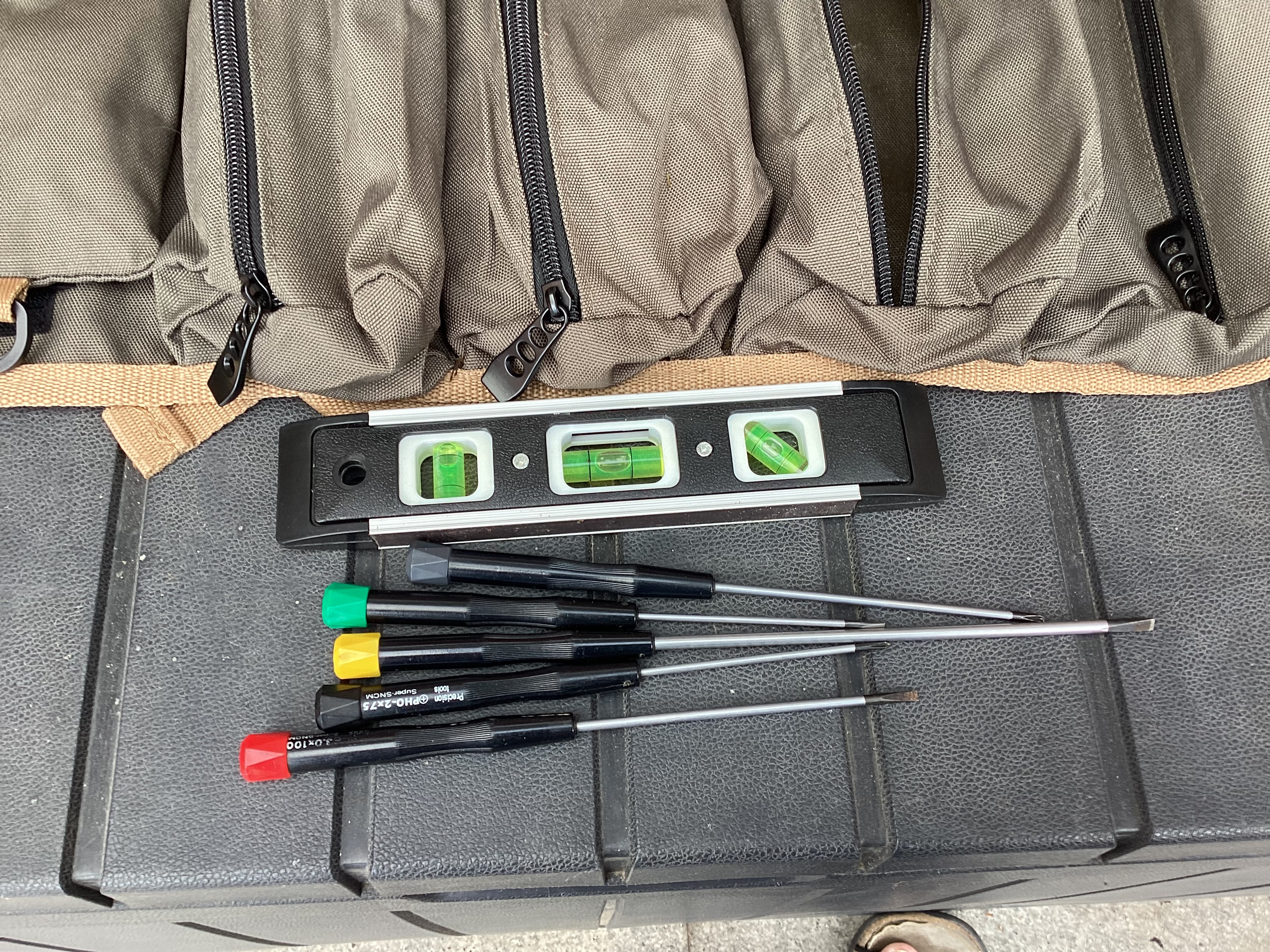
Finally some instrument screwdrivers… and a spirit level (Why?)
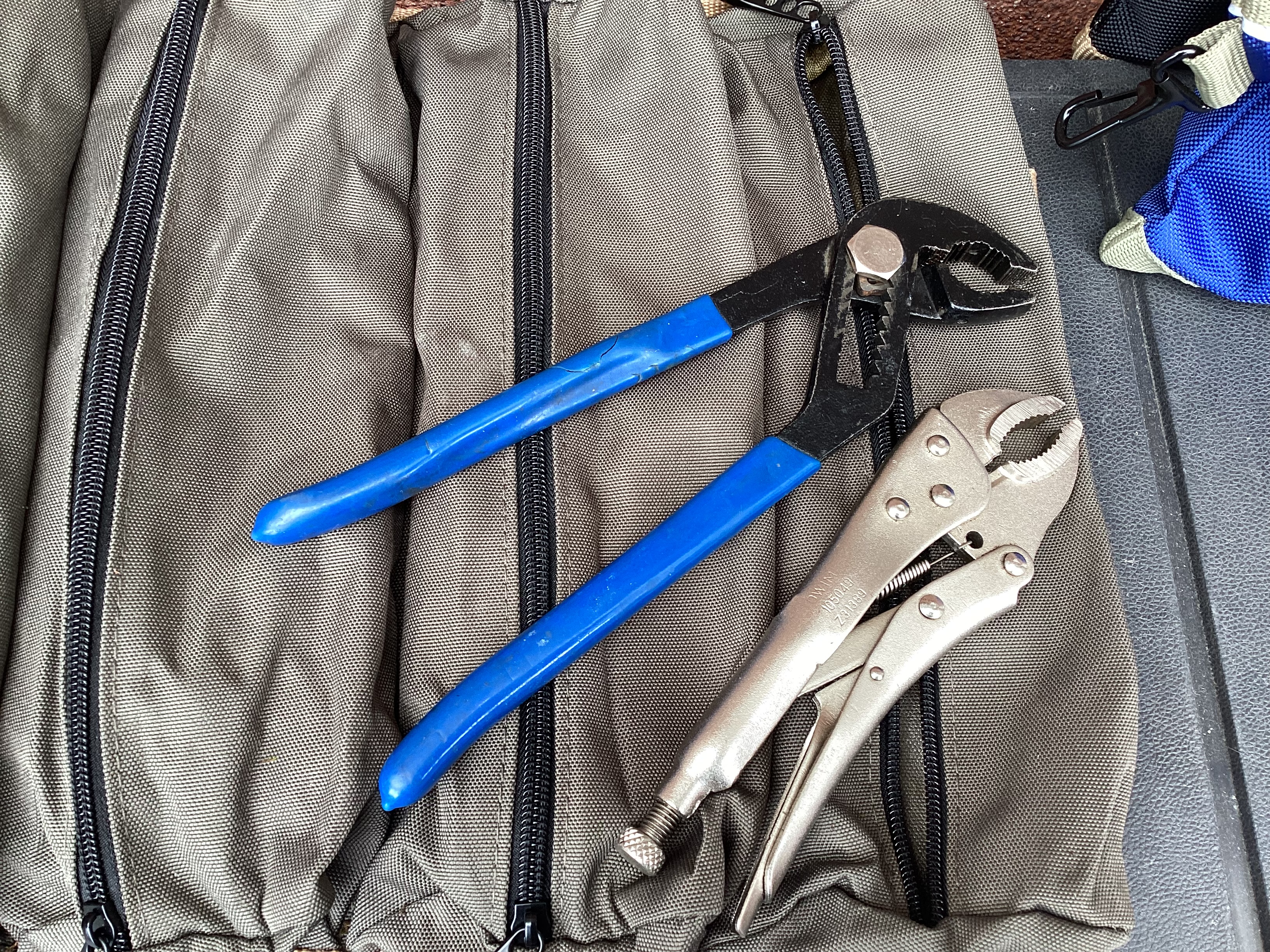
Last compartment… still working on it…. I did find my other pair of plumbers pliers though!
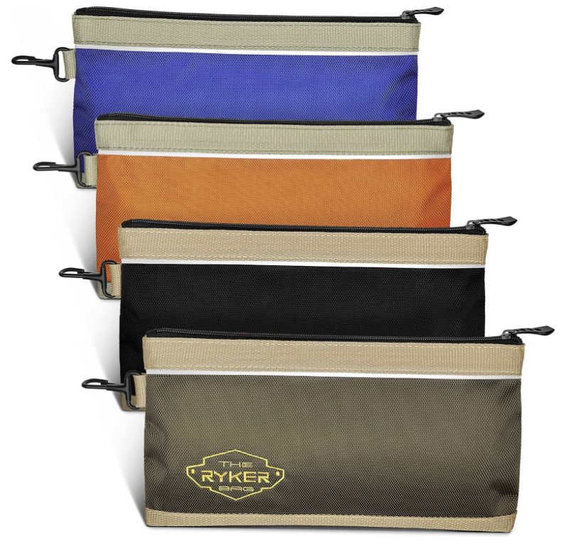
Finally…
Last two tool bags…
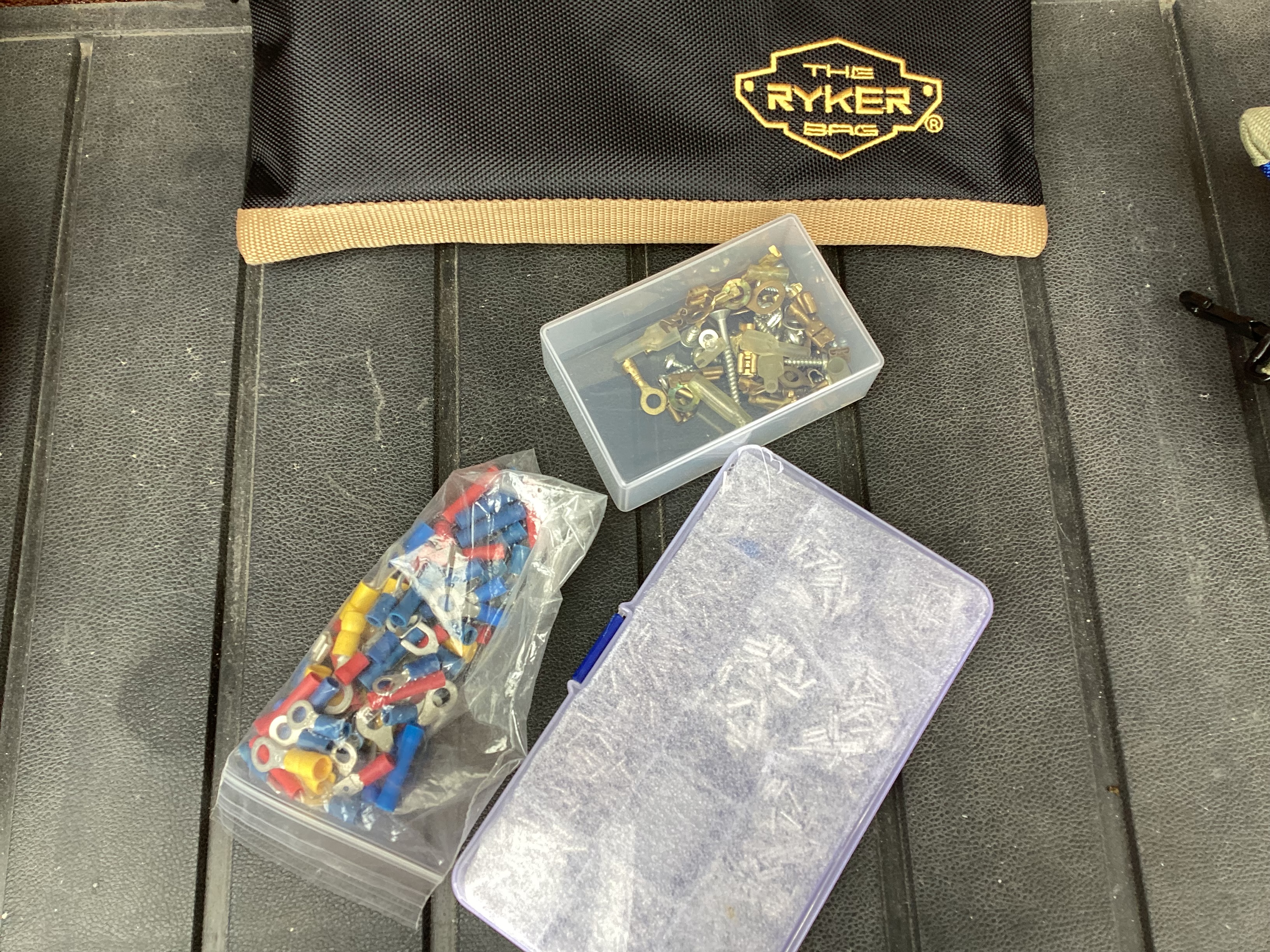
Odd collection of crimps and a full set of cable ferrules…. The spares box in the 5th Wheel has a full set of crimps… spare 13 pin plug, MelTruck EBS 24v 7 pin plug for the brake system, Fuses, Heat shrink, stainless fittings for the sun canopy, sets of stainless screws, cap head bolts, nuts, washers etc. If there is enough interest I’ll go through my spares box in a future article.
The business card style box (photo below) was a bit of a find. I was looking for removable draw organisers fr the workshop and after a lot of searching came up empty. However changing my search to ‘business card boxes’ found these… a box of 100 only cost me about £20 delivered. removing the lids and using them as trays as well gave me 200 storage compartments. I’m now on my second box of 100.
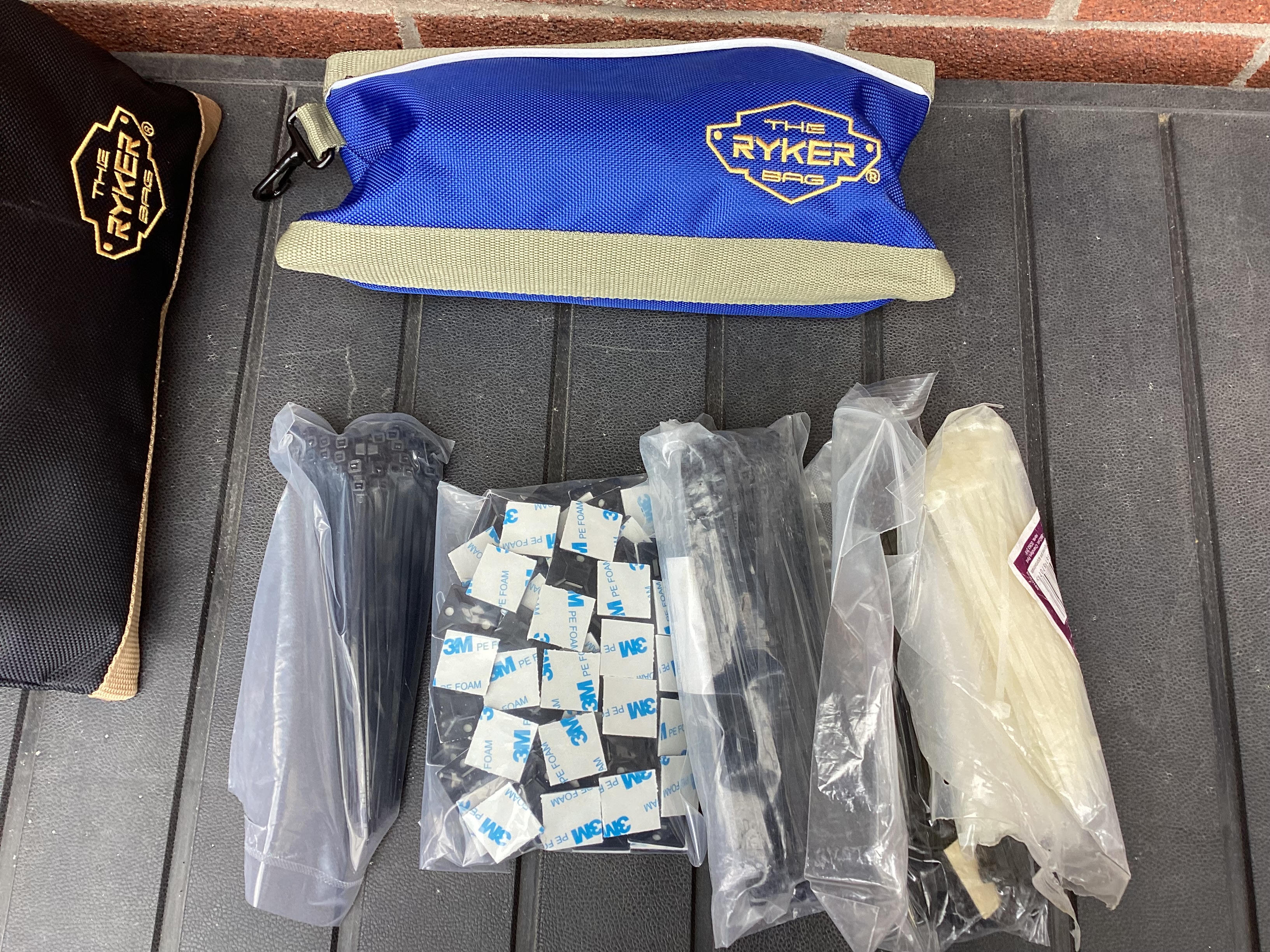
…. and you can never ever have enough tip ties…..
So that is a quick roundup of “What’s in my tool bag” thingy posts on you-tube. Not very interesting for 99% of people out there, but everyone seems to do it now and again.
So, I’ll bet the next question is…. “OMG love the bags where can I get them from?”
All available from Amazon…. I’m not affiliated with Ryker or sponsored by them, but I will get a few pennies if you absolutely can’t live without these and buy them through the links below. In the couple of months I have been using them I find that they are good quality, stitching and zips are up to mustard and the material seems to be hard wearing.
There are other similar products available if you follow the links on to Amazon, some cheaper too. You might find something that is more suited to your needs and price range, but have a look at tool bags instead of tool boxes. For me it was a bit of a game changer and space saver…. no to mention the weight and the fact I don’t need to get a big tool bucket or box out that contains everything.