I’ve had quite a few people email me asking for more information about the Victron system for a caravan that I was planning mentioned in the previous post. As this seems to have generated a number of questions, rather than give detailed answers to each one I thought I’d post the drawings. For the moment it’s on hold but here are the drawings.
While Victron would seem the obvious choice, there are a number of recent new products from Sterling Power that have rekindled my interest in the project…. watch this space.
Sometimes things you take for granted and have in your toolbox of fault-finding tricks are a dark art to others.
I was talking someone through a bit of fault-finding on their vehicle and asked if they had measured the current in the circuit. “No” came back the answer. I asked what type of fuse and rating it was and asked the person to just put their voltmeter across the fuse and tell me the voltage across the fuse. “Ah… that’s about 3.2 amps then” I said.
“How do you know that?”
Simple really – all fuses have a resistance and if you know that you can work out the current from the voltage drop. Even simpler really – there are tables for various fuses that have it all worked out for you. I have a selection collected over the years stuffed into the lid of my tool box, along with a lot of other junk paperwork!
I created a volt drop table based on PEC (Pacific Engineering Corporation) fuses that are supplied as OEM fuses in most Japanese, Korean and European vehicles however it is pretty accurate for almost all other makes of the same type of fuse. I printed mine out, laminated them and added them to the collection in the top of my toolbox.
It’s quite easy to use. Just set your multimeter to read DC mV and read the voltage displayed. Now select the fuse type, in this case an ATO fuse – the most common used in vehicles, caravans and motorhomes and from the chart look down the left column until you see the voltage measurement that matches the one on your multimeter… lets say 0.011 volts (11mV)
The fuse is a red 10 Amp fuse so follow the 0.011 volt line across until you get to the 10 Amp fuse column and read the current figure… in this case 1.3547 or 1.3 Amps. It’s as easy as that, no need to break the circuit to put your multimeter in as an Ammeter.
I have a couple of these cheap handy plug-in ammeter’s… although they do have limitations and only work up to 20 Amps.
Although the table is based on PEC ATO/ATC and MINI fuses (download info below) it is pretty close with most manufacturers fuses and as a general reference for fault-finding will be good enough to 0.1 amp.
If you need to know the actual current through a circuit, you need to use an ammeter and not rely on tables but for general work they are close enough.
These tables also come in handy if you are trying to find out why a battery is draining. Without turning anything on it is easy to run through a fusebox checking to see if any circuits have a current drain on them without having to constantly pull fuses and insert an ammeter, which sometimes can upset or reset the circuit you are working on.
One thing to remember with this test if you’re tracing a fault, is you are only measuring the volt drop across the fuse to determine current. You really need to know how much current you should be drawing. For example, If I was testing the 12 volt fridge circuit fuse and I only got a voltage drop across the fuse that calculates to 6 Amps then I’d know there was an issue somewhere along the circuit as I’d be expecting around 10 Amps or more.
A word from our Safety Officer…
Oscar would like to remind you that working on a live circuit has risks and never attempt to undertake volt drop measurements on mains circuits. Most cheap multimeters do not have the internal protection or fused test leads. Be safe. Be like Oscar.
You can down load the table in PDF format (4 pages) and either print them out or save them to your device from the following link:Fuse Voltage Drop Table
Unfortunately due to a lot of my drawings and text being used elsewhere without credit back to CaravanChronicles.com I’ve had to start putting watermarks on a lot of things. I hope this doesn’t make the table too difficult to read.
P.S. Someone told me that everything on the internet can be improved by cats and my “likes” would go through the roof!
A couple of days ago one of Caravan Chronicles readers, Vic, posted in the comments section of “Understanding Caravan and Tow Car Electrics” that he recently flattened his car battery by leaving his caravan connected to his car. Here’s what he posted:
Hi Simon, while travelling across Spain I made an overnight stop and left the caravan connected to the car electrics I also hooked up to mains. The next morning the car battery was flat, I’m sure I’ve done this before with no consequence. All I can think is that european site wiring can be suspect.
brilliant article.
OK, that got me thinking…
Was it the car-off-van switch faulty? Was there another fault of some sort? I asked Vic for the details of his caravan and he replied it was a 2009 Bailey Senator California. I don’t know the exact details for Bailey electrical schematics, but it should not be too difficult to work out what might be happening. I started to think of various failure scenarios that ‘could’ account for Vic’s problem. At this point I have to say I’m indebted to David Rose for sending me information about the electrical services in Bailey Caravans.
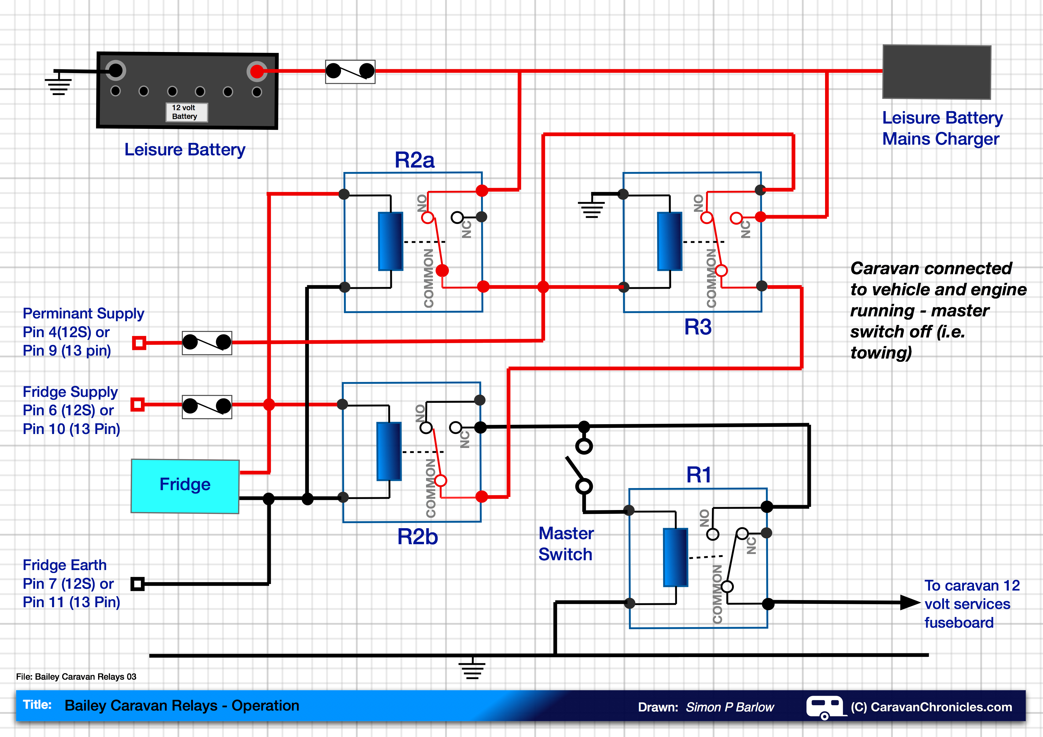
Looking closely at the schematic of the control unit, it all hinged around the correct operation of four relays. Here is the schematic I have drawn out in a simplified form:
The drawing (above) shows the four relays – R1, R2a & R2b, R3 as they are set when the caravan is not connected to the vehicle and the master switch is off. The red lines show what part of the circuits are live. The master switch controls relay R1 and when energised by turning the Master Switch on allows current to flow to the caravans 12 volt electrical system via the 12 volt fuse board.
Above: We have now turned the Master Switch on and can see that relay R1 has energised and is allowing current to flow to the caravans 12 volt services. The caravan is not connected to the tow vehicle.
Above: The caravan is now connected to the tow vehicle and the engine is running. The caravan master switch is off. With the fridge circuit powered from the running engine, it energises R3, R2a and R2b. Relay R2b disconnects the master switch circuit so that it cannot operate R1. Relay R2a connects the leisure battery to the 12 volt permanent feed from the tow vehicle. R3 energises, but only switches the feed for the master switch from the leisure battery to the permanent 12 volt supply from the tow vehicle. As this stage it cannot be used to supply the master switch due to R2b being energised.
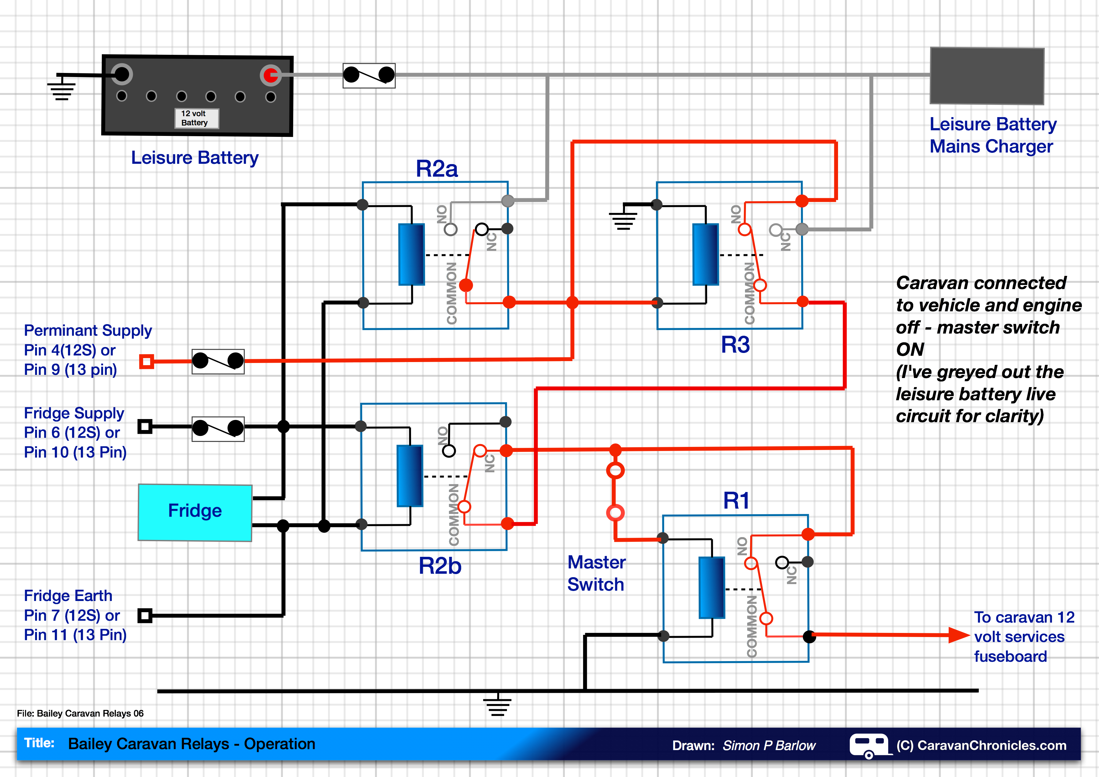
Above: The caravan is still connected to the tow vehicle, but the engine is off. Relay R2a and R2b that are controlled by the fridge circuit are now not energised and revert to the default position. However as the caravan is still connected to the tow vehicle, the 12 volt permanent feed keeps relay R3 energised, therefore supplying the Master Switch – not from the leisure battery but from the permanent 12 volt feed from the vehicle.
This now leaves us in the following position:
Above: The caravan is connected to the tow vehicle but the engine isn’t running. The master switch is on. The caravan now receives it’s 12 volt feed from the tow vehicle to power all the 12 volt services. I have greyed out the live circuits from the leisure battery. Even though the caravan is plugged into a EHU bollard, the 12 volt services will be run from the vehicle battery and not the mains charger/ leisure battery circuit. The fridge will continue to work on 240 volts as will any mains powered equipment.
So, it’s not a ‘fault’… it’s a ‘feature’ ! Leaving the caravan plugged into the car and turning the Master Switch on allows you to power the caravan’s 12 volt services from the car. Disconnect the lead from the car and the caravan will be powered from the leisure battery.