It seems such a long time since I posted anything.
Last time out with the Dreamseeker I noticed that the charging voltage when we were hooked up to the truck was only about 12.1 to 12.3 volts as measured in the Dreamseeker battery box.
I know that the VW Amarok puts out 14.6 to 14.8 volts, measured at the 13 pin socket AND indicated on the digital voltmeter I installed in the dash. So it was time to do a bit of investigating.
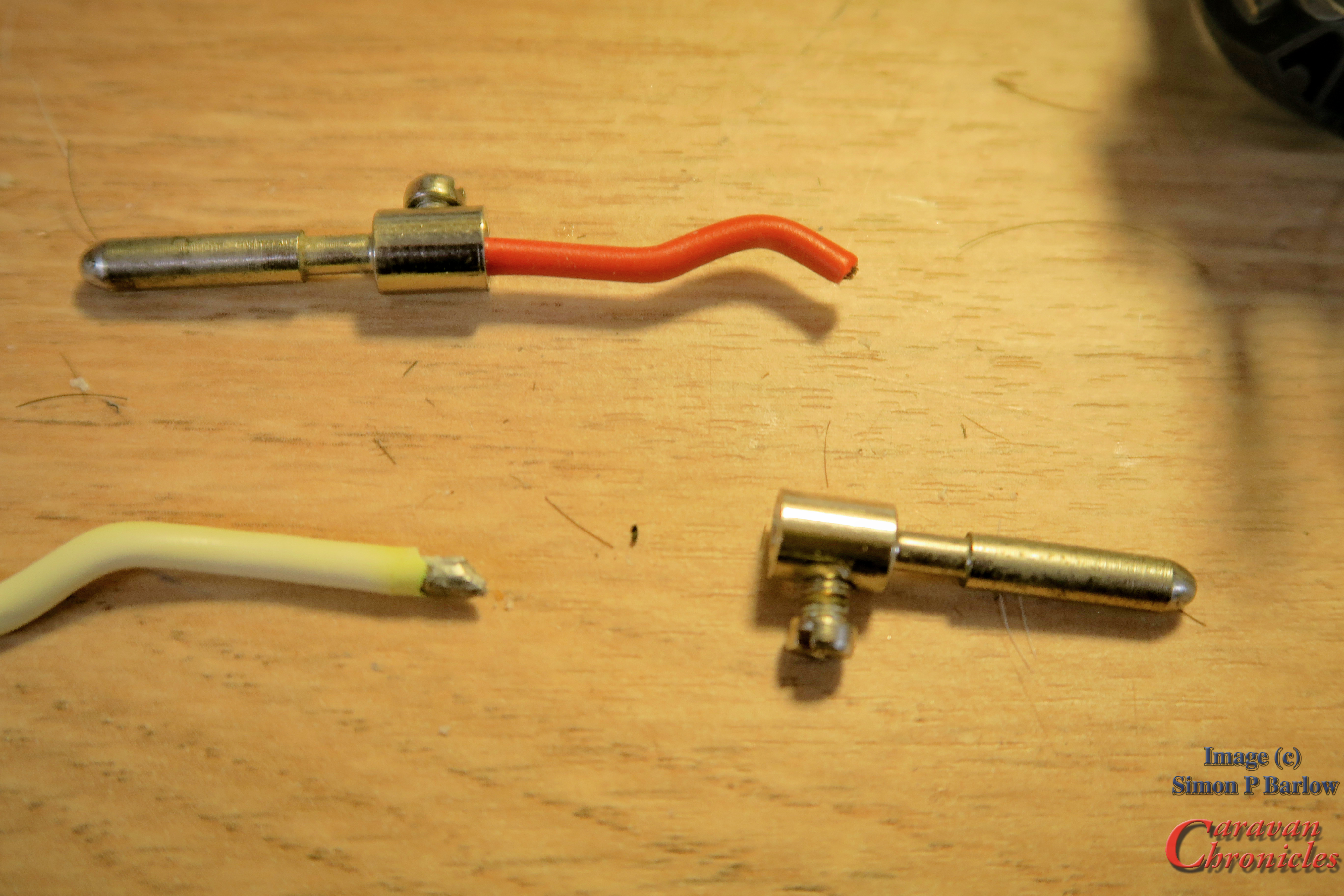
After measuring the resistance of the charging circuit and fridge circuit it was clear there was a bit of an issue. First stop was to disassemble the Dreamseeker’s 13 pin plug. All became clear…. The cable had been terminated in the socket with soldered ends and were suffering corrosion (solder very dull) and cable degradation….. the copper conductors when stripped of their insulation were black. All in all not good.

I wanted to replace the whole 12 core cable with a replacement but unfortunately I didn’t have a length in stock long enough. I usually keep a length suitable for replacing the cable and plug on a normal bumper tow caravan.
The simple solution for the time being would be to cut back as much as I could and install a new 13 pin plug with correctly crimped ferrules on the cable.
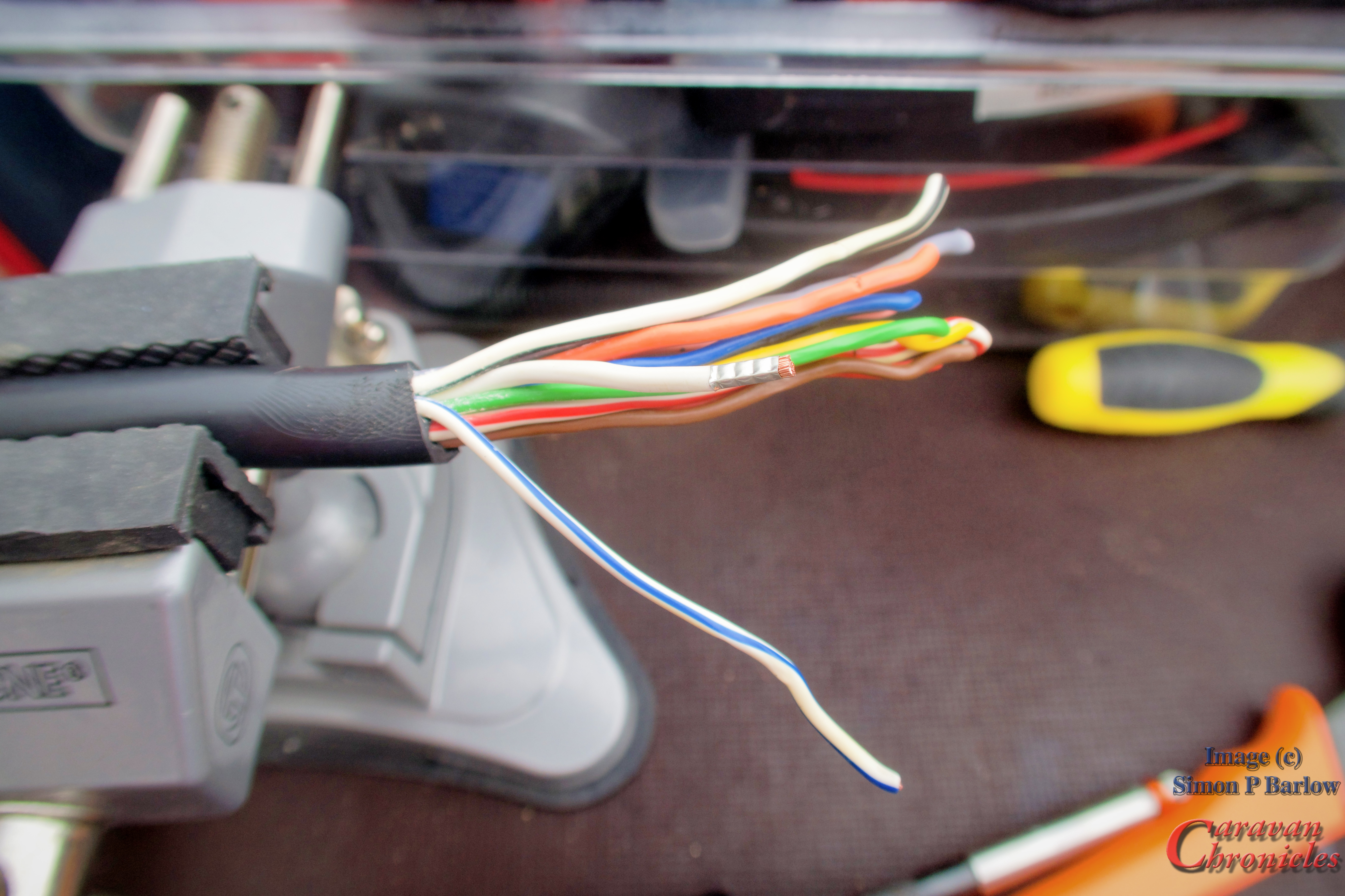
I cut off the old plug and stripped back the protective cover from the cable allowing enough to shorten the individual conductors to the correct length and inspect them for internal corrosion before crimping on the ferrules ready for termination.
The torque setting for these terminations are listed as a minimum of 5Nm to a max of 8Nm so I set my torque screwdriver to 6.5Nm. A happy medium I think.

The new plug was reassembled and I could get on with testing it. At the Amarok I measured 14.7 volts on the leisure battery circuit (same on the fridge circuit) and at the leisure battery I measured 13.9 volts and 9 amps charge, which considering the two 110Ah AGM leisure batteries are at the rear of the Dreamseeker I was happy with the loss.
Something I’m going to try…
While I was doing all this I started thinking (I’d also just seen the price of 13 core trailer cable per metre!) Why are we using this cable?
I have a length of woven kevlar cable sleeve (used in the aviation world) and I could thread my own cable…. upgrading the 1.5mm2 to 2.5 and the 2.5mm2 to 4mm and the “cable” would… (actually is…. as I have made one up now)… a lot more flexible than the existing product as it allowed the individual cables to move and slide past each other. I also used marine grade coated copper cable, so no corrosion of the strands.
4mm2 cable was a bit of a faff to terminate in the commonly available 13 pin plugs, but I believe the genuine ” German Jager manufactured plugs are acceptable for 4mm cable and they even have a crimp terminal version. So I’m going to do a bit more investigating as if I can get 4mm2 leisure battery and fridge circuits from end to end, that will reduce the voltage drop… which is always a step forward.
I’m also looking again at a high current circuit using Anderson connectors between the Truck and 5th Wheel. Currently I’m thinking of a 50 amp circuit with a 30 Amp DC to DC charger installed in the Dreamseeker…. ready for the battery upgrade. (along with a solar install, when I can find a suitable company to work with on that project)
Tourfest Northwest… as arranged by “The Caravan Addys”
Sue and I will be at Tourfest Northwest hosted at Donkey Creek Farm near Warton in May (24th to 28th) drop in and say “Hi”……” see you in a bit“