
Tags
Battery Charging, Leisure Battery Charging, Maintenance, Project, Sterling Power, Sterling Power Wildside, Technical
Planning the Install
Remember the Six P’s… “Proper Planning Prevents Piddling Poor Performance”… or something along those lines! Before we start hacking away at the multitude of cables (and my email inbox fills up with help requests) we need to pull out the relevant electrical schematics from the handbook. Our caravan is a ‘dealer special’ based on a 2011 Swift Europa 550 fitted with a Sargent PSU.
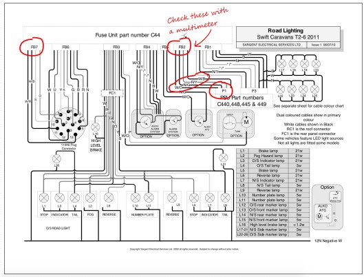
We can see from the schematic below that the 13 pin plug enters into the caravan and terminates with two connectors – FB6 and FB7 on fuse unit C44 which in our caravan is located just next to the front draws near the water pump. FB6 is all the road lights and we can ignore this.

The cables we are interested in are from pins 9,10,11 & 13 which are coloured Orange, Slate Grey, White/Black and White/Red respectively and terminate in connector FB7. We need to now look for these leaving the Fuse Unit and heading off to the PSU.
The most likely candidate will be connector FB2 with four cables going to connector P1 on the PSU. If they are all 2.5mm² it’s a good clue these are the ones we want. We will need to check these with a multimeter though to be sure. The colours have changed too so we will need to confirm what the new colour is for each circuit.
So that’s the input side of the Wildside potentially sorted out, now we have to find the fridge connections. Looking at the schematic for the Power Circuits we can see that the fridge is connected via four cables. One directly to Neutral and the other three to P7. We can also see from this schematic that the leisure battery is connected to P2 via a 20 Amp fuse. This tells us two things – the wiring is rated for 20 amps and we will have to upgrade the cable size from the Wildside unit to the leisure battery.
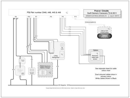
For the fridge… We are interested in the two cables that power the heating element and on the drawing they are coloured W/B and R/Y (White/Black and Red/Yellow) and originate from connector P7 on the PSU.

We have now identified on the schematics the cables we need to look for and where they run from and to. Next step is to create a new schematic using the information from these two drawings to show how we are going to connect in the Wildside unit.
To The Bat Cave…. err Drawing Board!
If you are handy at using a drawing package such as Sketch-Up or similar (I use “AUTODESK® Graphic” on my MAC) you can have a go at drawing it out, or simply just use a sheet of paper. The important thing here is you DO draw it out.. this is not an option, its a mandatory task!
TIP: If you are drawing this out by hand on a sheet of paper, it might help to photocopy your caravan schematics and cut out the relevant sections… like the fridge and stick them to your drawing to make it easier.
So here’s my efforts….
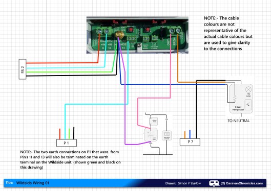
If you remember in part 1 I said we will need to make five connections…. not including the neutral. Well we have the five connections. After looking at the layout I decided not to cut the current leisure battery connections to upgrade, but to install a new Positive and Neutral cable alongside the original cables. This will mean however I will need to drill a new hole in the battery box and install a sealed cable gland.
The three cables that we cut on P1 that are now unconnected should, in theory not be part of any circuit. However to be sure I’m going to terminate both the neutral cables (originally connected to Pin 11 and Pin 13 to the neutral point on the Wildside unit.
The cable that was originally connected to Pin 9 I’ll just crimp on a blind connector and secure out of harms way. I am not sure if this might need to be connected to a +ve supply. There are a couple of things that I’ll need to check, for example, the toilet flush always works when the caravan is connected to the tow vehicle – with or without the engine running ( handy if a quick P(it) stop is required!).
Now… To The Bat Cave!
Well it might be a couple of days as I have just ordered a few bits and pieces I don’t have in stock in the workshop… and I’m still procrastinating whether to do the install as a video to accompany my written ramblings.
Coming up in part 3. I attempt not to destroy our caravan, do a lot of crimping, consume a lot of coffee and I may be swearing a lot on camera!

Hi Simon just reading this post some years later, i have just purchased a votronic unit from road pro and its going in to a swift 2018. My psu is different yours, did you ever ever wire it up to the sargent unit or did you keep it all separate ?.Take it you upgraded the wires, did you bypass the sargent unit completely
Hi Kevin
I bypassed the Sargent unit completely. Also replaced the mains charger with a proper multistage one.
I did the same removed the sargent mains charger, its the B2B thats giving the issue even with a similar unit to the wild side i cant get the voltage over 13 volts to charge the lithium battery. An ides that might help was cold when i tried it and battery was nearly full
Pingback: Vehicle Wiring Projects… Some Thoughts. | Caravan Chronicles
Pingback: Overland Vehicle Electrics and Other Stuff… | Caravan Chronicles
Pingback: For Anyone Restoring A Vintage Caravan… | Caravan Chronicles
Pingback: Euro 6 Engines, Smart Alternators and Your Leisure Battery… | Caravan Chronicles
Pingback: The problem with information from the internet… | Caravan Chronicles
All very interesting Simon.
Just for interest sake. If you have found a connection block with pin 9 & 10 and the 2 corresponding earths, could you not just unplug this and wire the wildside unit between the two halves
I.e. The supply from the car goes into the input side of the unit and the out put side of the unit connects to the van side plug going to the Sargent psu. The earths can then be connected to the unit as well.
I understood the unit is only a voltage increase / stabiliser and as such all this would do it produce the correct stable voltage the car is ment to supply.
I wonder it the multi plug is available as a pat so that you would only need to plug the unit in.
Or,
Am I missing something.
Ian.
Hi Ian
Until I actually get out to the caravan and confirm a few things, making up a lead to simply allow the connections from the Sargent unit to be simply moved across may be an option. I need to check exactly what the connectors are and if they can be sourced easily. I also need to confirm some of the functions of the Sargent unit continue to operate if I make the changes.
As far as I know this will be the first actual install in a caravan so there might be a bit of additional testing required during the install.
Since writing the post a couple of hours ago, I have already changed how I’m going to connect to the battery.
Once I’ve got it all installed and tested, it might be posable to be able to manufacture a wiring loom for specific caravans so it becomes “plug & play”.
Sterling caravans seem to be straight forward, next I have got to look at how it would be installed in Bailey and Luner caravans.
The Wildside unit is a bit more than just a voltage step-up/stabiliser box, once you start getting into the detail and customising the programme.