
When undertaking an electrical project for your caravan or motorhome one key consideration is what type and size of cable to use. Selecting a cable that is too small for the task and you might risk melting the cable insulation or damaging equipment due to voltage drop.
A few key terms:
Cross sectional area of the conductor – sometimes called ‘cable size’
Given as mm², it describes the total cross-sectional area of the copper conductor. Cable will be sized 1 mm², 2 mm², 4 mm² etc. and may be written as 1 mm, 2mm, 4mm. This is not the diameter of the cable.
Conductor Number and Size
Usually given as 19 x 0.41 or 19/0.41 which decoded means 19 strands of 0.41 mm diameter wire.
Current Rating
Always given in amps for the cable at a standard temperature (20 Deg.C) in free air. If you bundle cables or install them in conduit you have to down grade the current rating. Each manufacturer will have charts for this. It is unlikely though for moat projects in caravan’s or motorhomes you will need to factor this in.
Overall Diameter
This is the overall diameter of the cable including insulation. Don’t confuse cable diameter with cross-sectional area.
Lets start by looking at cable construction.
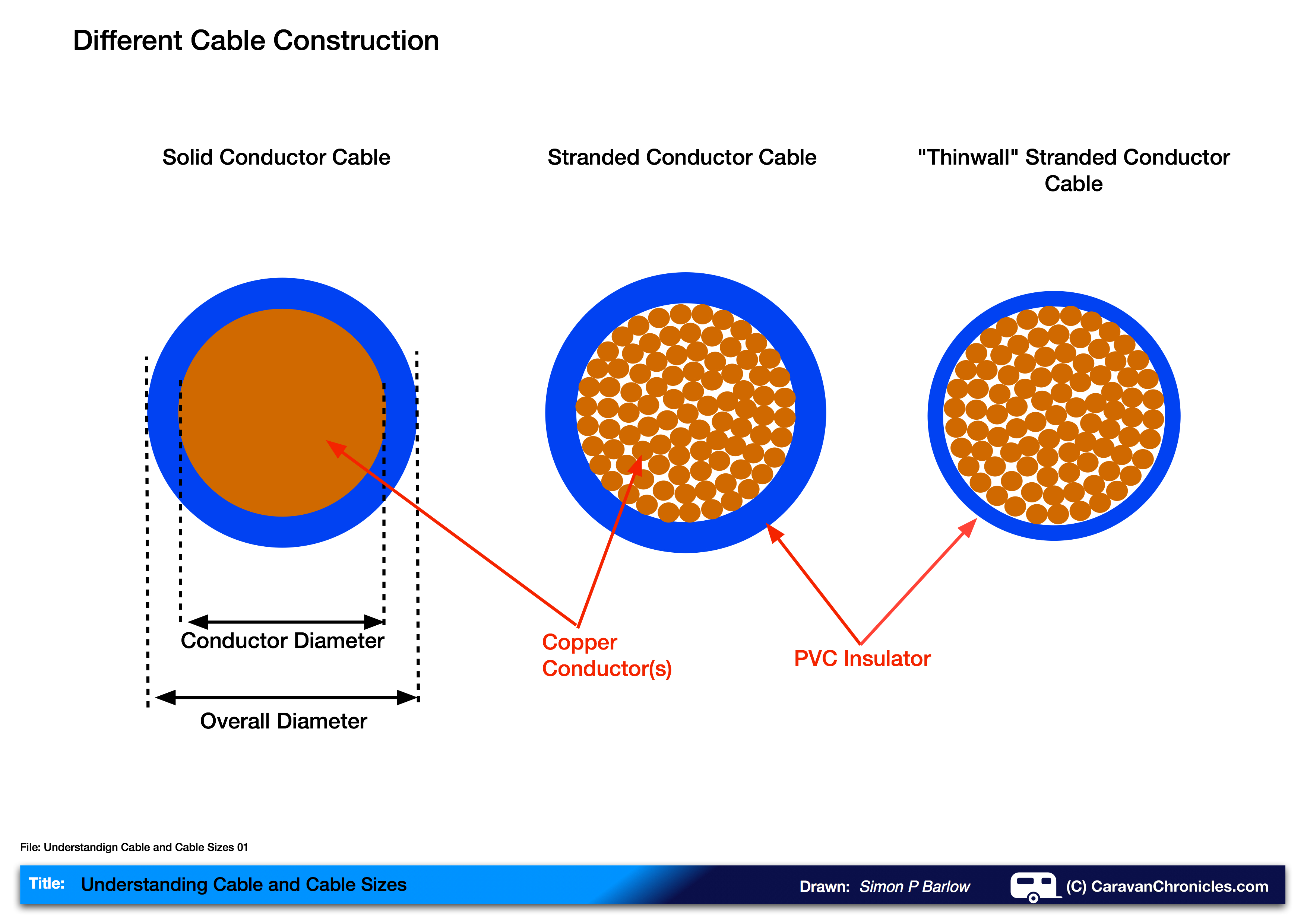
Cable comes in two main types, solid and stranded conductors. Solid conductor cable is usually reserved for the cables installed in domestic and industrial buildings. It is not a flexible as stranded and therefore should never be used where vibration or movement could disturb the cable. Copper work hardens with flexing becoming brittle and eventually will crack creating a higher resistance at the fracture point and could lead to overheating.
Stranded conductor cable, sometimes called “flex” in the UK or “cord” in the USA, is built up of dozens of thinner strands of solid copper conductors. These smaller diameter strands allow the cable to bend easier and slide over each other inside the PVC insulation so that the bending force and stress is reduced. However repeated bending will damage the cable over a long period and may cause the individual strands to break within the cable reducing its overall cross sectional area and ability to carry its rated current creating a hot spot.
“Thin wall” Cable.
Thin wall cable has a thinner layer of insulation – as its name suggests, it is usually made from a higher grade of insulating material. It’s generally lighter and the insulation is denser and more resistant to impact damage and abrasion. The insulation also has a higher melting point (see “Insulation” below) of around 105° C. Because of the benefits It’s been adopted by nearly all the vehicle manufacturers. The down side is it’s less flexible and sometimes unless you have the right cable stripping tool it can be difficult to strip the insulation off the conductor when making terminations.
Thin-wall cable made from special coverings – Kynar (Arkema) and Kapton (DuPont) are commonly used in aviation.
“Tinned” Cable
Some stranded copper cable is tinned (looks silver when you strip the insulation off). Tinned cable is usually used where corrosion has to be taken into consideration, such as marine use. If ordinary copper cable is used, the copper conductors turn a dull brown or in severe cases green at the terminations. This surface corrosion can ‘seep’ back up the cable and the only way to solve the problem is to cut off the end of the cable back to bright copper and re-terminate. Using adhesive lined heat shrink tubing over crimp connectors can help in slowing the effects of corrosion but not eliminate it.
Number of strands in a cable.
The more strands in the cable, the more flexible and kink resistant it is going to be but also the cost will increase. The lowest number of strands is 7 – one in the middle surrounded by 6. The next is 19 which is one in the centre surrounded by 6 surrounded by 12. This can sometimes be found being used as battery cables.
A typical cable strand chart from a manufacturer can be seen below:
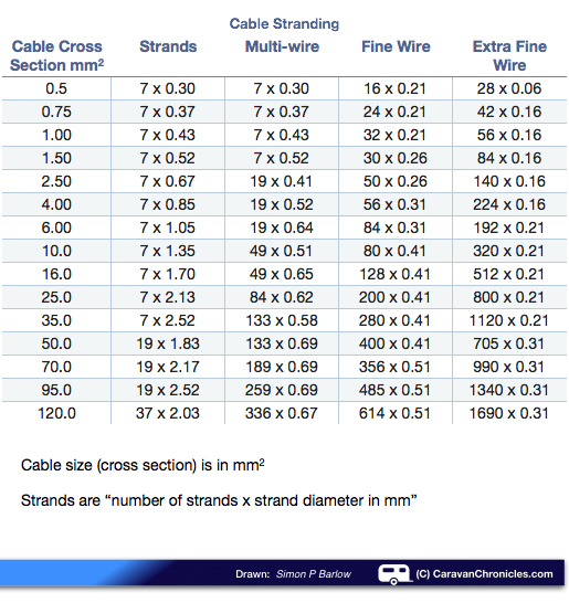 These figures are for typical cables from one manufacturer. They do sometimes differ in strand count and strand diameter depending on country of manufacture and quality of copper. Typically “Multi-Wire” or “Fine Wire” is used for caravan, motorhome or automotive use. Cable that is manufactured in America is sized using AWG – American Wire Gauge (sometimes referred to as “Brown and Sharp” Gauge) Increasing gauge numbers denote decreasing wire diameters.
Cable Insulation
Generally they fall into 5 categories based on thermal rating:
- Up to 80° C – Polyethylene, Neoprene, Polyurethane, Polyvinylchloride (Semi-Rigid)
- Up to 90° C – Polypropylene, Polyethylene (High Density)
- Up to 105° C – Polyvinylchloride, PVC (Irradiated) Nylon
- Up to 125° C – Kynar (135° C), Polyethylene (Crosslinked), Thermoplastic Elastomers
- Up to 200° C – Kapton, PTFE, Silicone
- Most likely cable you will use will be semi-ridgid Polyvinylchloride
Choosing which size cable to use
OK, this is the bit you have been waiting for! right there are two things that you have to consider when selecting a cable size. The first is the load that the cable has to supply and the second is the length of the cable. Both these have an influence on the cable size.
On the face of it, choosing the cable size should be easy… there are charts that state “For this size cable the maximum current is X”, but hold on a minute there is a bit more to it.
All cable has a resistance and it’s given as ohms per metre – “W/m”. Some manufacturers give this figure, however others give the voltage drop expressed as “mV/A/m” ) milli-Volts per Amp per metre . You have to make sure your using the right figure for the calculation.
Think of the brake lights on your caravan. We have a 1.0 mm² cable connected to a battery that is 12 metres long that needs to supply two light bulbs that have a total load of 50 watts at 12 volts, how do we work out the voltage drop?
OK, here’s a worked example using both methods… the answer will be the same I promise !
Lets use the ‘W/m’ – Ohms per metre figure: In this case the manufacturer states it’s 0.038 W/m. First we need to work out the current, so we use P / V = I or 50 watts / 12 volts = 4.17 Amps
So if we were to use a 1.0mm² cable which has a resistance of 0.038W/m and it’s length from the battery 12 metres, then the voltage drop would be:
Vdrop = 4.17A x (12m x 0.038W/m) = 1.901 V
OK now lets use the mV/A/m figure: In this case the manufacturer states it’s 38 mV/A/m. Again we need to work out the current required, so we use P / V = I or 50 watts / 12 volts = 4.17 Amps
Now we can use the following formula…
Vdrop x Current x length of cable in metres and divide by 1000 (to convert mV into Volts).
Vdrop = 38 mA/A/m x 4.17 Amps x 12 metres = 1901.52 mV / 1000 = 1.901 Volts.
I told you the answer would be the same!
Easy bit coming up… of course we have to calculate the voltage drop on the neutral cable and if we use the same size cable – 1.0mm² the voltage drop will be identical – 1.901 Volts, giving a total of 3.802 volts.
So we can see that although the cable size, 1.0 mm² is rated to handle the 4.17 amp load, if we used that cable the voltage drop would be excessive. As a rule of thumb, the voltage drop should be no more than 3%. In our example it’s 31.6%.
Don’t forget if your neutral (return) cable is supporting more than one circuit the voltage drop will be greater. You would need to calculate the Vdrop on this cable assuming that all the circuits were working. So if it were supporting two 50 Watt circuits it would be:
Vdrop = 38 mV/A/m x 8.34 Amps x 12 metres = 1901.52 mV / 1000 = 3.803 Volts.
To sum up…
Choosing the right size cable is not difficult now you understand some of the principles behind your choice. Try and keep the voltage drop below 3% and always make sure the fuse that protects the cable is rated at, or below the cables rated current capacity. Stick to those rules and you should not have any problems.
I hope you found this guide useful.
Further Reading:
Understanding Watts, Amps Volts & Ohms
Understanding Caravan and Tow Car Electrics
.
Copyright © 2011 – 2020 Simon P Barlow – All rights reserved

This is a very nice article
Learning so much by your articles and the questions and answers .
With regards to cable size, if all negatives return to a common ground (buzz bar) and that then returns to the negative of the battery, will that cable need to calculate all the returns to ensure the cable is within 3% of voltage drop?
The negative between the bus bar and battery terminal needs to be sized for the max current of all the equipment running. The voltage drop on that leg can then be calculated. Adjustments can then be made to the cable size based on that voltage drop.
Hi, firstly thanks for you articles. I’m getting some great information from them. A question on cable sizing, I’ve been scouring the internet to find the answer to this question.
In choosing cable size. When considering amp rating and cable size, do you only think about constant load or load spike as well. E.g. I want to hard wire a air compressor in my truck, and it can draw up to 90amps especially on startup. However it does not draw near that much “normally”. So do you have to size your cable to allow for momentary “spikes” or should you consider “normal” operating loads.
This question came about as I have also read that 12v circuit breakers are designed to trip after a period of high load, way over its rating. Some have said circuit breakers are designed to trip when 200% of their rated load is being drawn through for a period of time before they trip. So I was wondering if this same principle applies to cable size vs load. Hope this makes sense.
Hi Peter
Cables are always rated based on a constant current. SO a cable rated at 50 amps will be OK carrying a current of 50 amps over a long period, however it will be OK for short ‘overloads’ of usually around 50% with out too much worry as long as it is for only a few seconds.
With fuses there are various types, the main two are “normal” and “slow blow”. A normal 10Amp fuse will usually blow as soon as you exceed 10 Amps, a Slow Blow type will let you exceed 10 Amps for 30 seconds or so. This is the same with low voltage circuit breakers. Some are designed to trip at exactly their nominal rating, others will allow you to exceed the nominal rating for a short period of time.
With on board air pumps such as Viair and ARB just go on what the installation instructions specify for cable size and fuse ratings.
If you want to increase cable size to reduce voltage drop over a longer run that’s OK but stick to the fuse or circuit breaker size as specified by the manufacturer. They have tested their equipment with that size breaker and are confident that the startup current will not blow (trip) the circuit protection.
I have installed a few Viair and ARB units with receiver tanks over the years and never had any problems with the rating of the protection device they specified being too low.
Ok great. Thanks for the response. I thought as much but could not find guideline as to the general percentage spikes can go over the amp rating. I have a other brand of compressor that claims 90amp max output. Others who have tested have verified the claims but it is only at startup for a few seconds. It is a brand that comes with alligator style clamps for the battery so I’m going off the script a little in hard wiring it. But I will test for my self the amp draw before making a decision whether my cable is adequate. Thanks again for the insight.
Pingback: Getting All Charged Up – Part 1… | Caravan Chronicles