A lot of new caravans now have the ability on a ‘super pitch’ to be able to attach a mains water feed directly to the caravan without having to have an Aquarol as a water reservoir, and this seems like a good idea. I started looking at the options available and was surprised at the cost of the only suitable system for our caravan. I also wasn’t keen on the plastic regulator. This got me thinking, maybe it was time for a little Caravan Chronicles DIY project.
I wanted to come up with some sort of contrivance that was assembled from stock components that were easily available anywhere. After a brief search on Amazon I came up with my shopping list and ordered everything (see links below).
The result was a simple to use commercial pressure regulator that I could use our existing blue water hose that originally connected to the Aquarol and standard hose fittings that allow me all the options for connecting up.
As a temporary mount I used a couple of the small plastic hangars that Fiamma sell that slide into awning rails allowing you to hang things from. In this case a couple of cable ties held it in position. I’m currently in the bat cave folding a small aluminium plate to mount the regulator on that slides into the rail and has a foam padded back to protect the caravan. I opted to use brass fittings for the hose connections rather than plastic just for durability.
So how did it work out?
Well on a recent trip to Southport Caravan Club site (where the photos were taken) it worked extremely well. The initial set up was easy and to start with I reduced the pressure using the small screw on top of the unit to about 0.5 bar (7 PSI) to ensure I didn’t over-pressure the caravan plumbing. I increased this to about 1.5 bar and this gave an excellent flow rate with the added feature of not having to run the internal water pump.
Something that was in the back of my mind however was what if the regulator failed and full mains pressure was allowed through to the caravan’s internal plumbing? As I’d used a commercial unit, hopefully the chances of this would be very slim to non-existent as these units are designed to be permanently installed in commercial and domestic plumbing installations however I also added another little handy gadget at the tap end…
This ‘Y’ fitting has two small ball valves, one of each outlet. So when we go out, I simply turn off the appropriate ball valve. Having a ‘Y’ adaptor also allowed us to fill up our Brita filter jug or draw water off without having to turn the tap off and disconnect the caravan hose. All in all everything worked out perfect. (note I have since changed the blue hose adaptors shown for brass ones for durability).
One last thing…
If you are at all worried about water quality in your caravan, connecting up this way will allow you to thoroughly flush out your caravans water system and give you clean water from your caravan’s taps, (especially In summer too, when the sun has been warming up the water in your Aquarol all day) all you need to do is just run the tap for a minute or so to get cold fresh mains water.
I am often asked where to buy some of the products we use. Here are the links to the products. If you click on the links and purchase any of the items, a few pennies will go to helping the cost of running CaravanChronicles.com
It’s that time of year again… the mornings are getting lighter, the evenings longer and planning for the first trip of the year is well under way. But, what about your caravan or motorhome? It’s time for the de-winterising and annual deep clean. The easiest way we find to do it is to first create a list of the jobs to be done and make sure you have all the bits and pieces you need for the tasks. Our “go-to” shop for cleaning supplies is OLPRO, it’s easy to order everything for the season for both cleaning stuff and loo stuff. We have been using them for at least a couple of years now and haven’t come across any problems and have genuinely been satisfied with their products.
Arriving at the storage site with a trailer full of water and cleaning supplies!
As it’s now the ‘off season’ for a lot of caravaners and thoughts turn to sorting out those problems that we put up with on the last couple off trips, I thought I’d look at cable terminations. One of the problems that I’m asked about revolves around cable termination in trailer sockets and plugs. Like most things there is a right way and a wrong way of doing it and there is also the compromise.
So what’s the problem?
Well the problem is terminating a cable to a solid metal part. You will most likely see cables that are striped down to the copper conductors and the individual strands twisted together then inserted in a hole with a screw tightened down to hold the conductors. So whats the problem with this? When you tighten the screw it’s turning obviously and the end of the screw twists down on to the strands of cable, often breaking a few off and pushing quite a few out-of-the-way, usually in an average termination about a quarter of the strands are not held under the screw tip. The 2.5mm square cable you thought would reduce volt drop for the battery charging circuit is now reduced to something less and its current carrying capacity is reduced. Is there a solution?
The obvious one would be to solder the ends of the cable to stop this happening and it’s a great solution, but is does have drawbacks. When you solder the end of a flexible cable the point where the solder stops becomes a weak point and is susceptible to vibration and flexing stress and the thin copper strands transition from being flexible to a solid mass. This is why in aviation, marine and military applications soldering is not usually permitted.
The correct way that flexible conductors should be terminated is by crimping on a “boot lace ferrule”. These are simple brass tubes, sometimes nickel-plated that are slid over the untwisted strands of the conductor and crimped tightly. Some ferrules are just small tubes or ‘U’ shaped section machine crimped and some have a plastic insulator to help isolate the conductor when several are installed in close proximity.
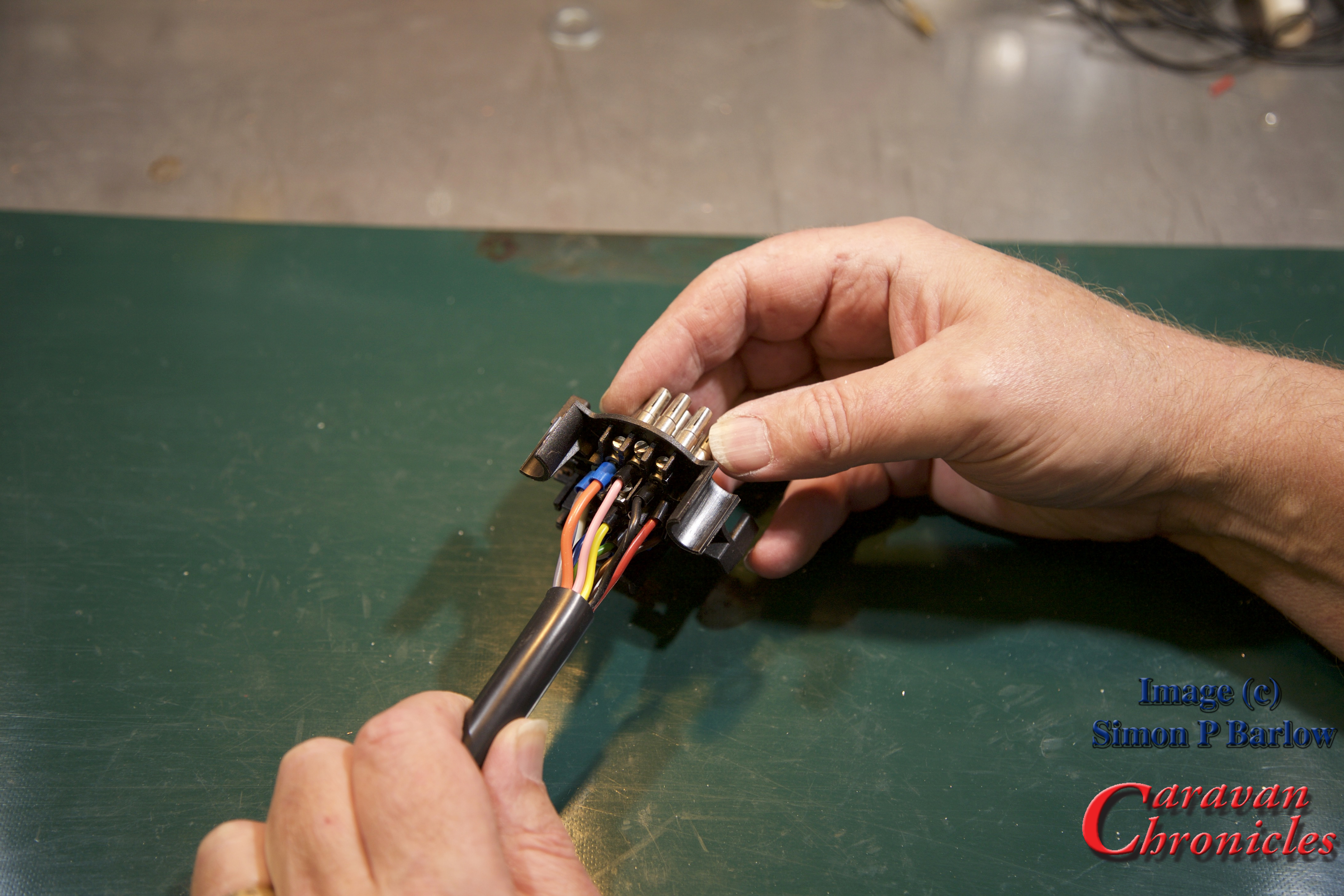
Here’s a simple step by step guide to crimping and terminating a 13 pin trailer socket. It could equally apply to a trailer plug.
For the photos I used a spare socket and short length of standard multi core cable. I have links to all the items, including tools used in the article in “Caravan Chronicles Shopping” at the end.
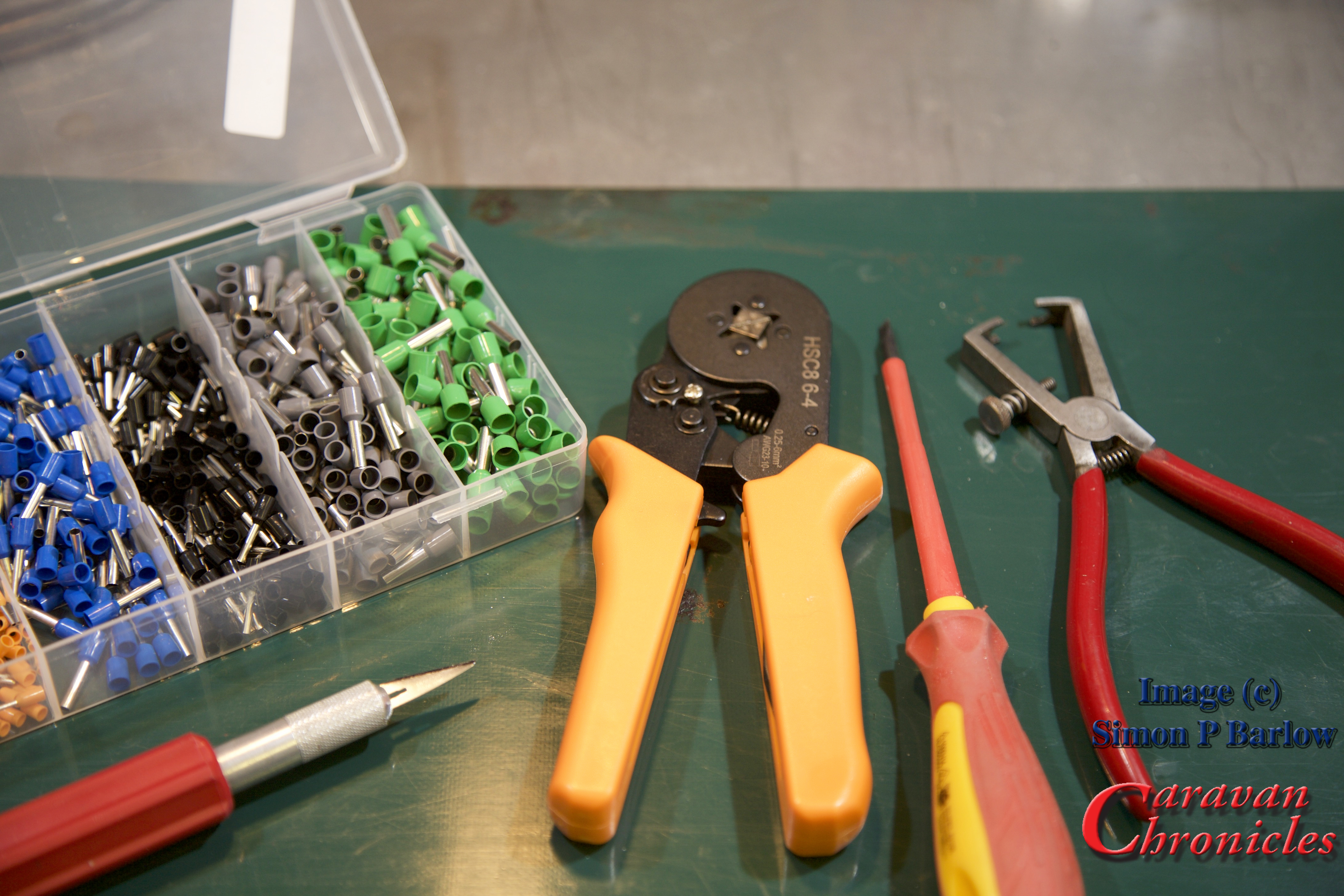
The tools required are a sharp knife, cable strippers, screw driver, ferrule crimps and the ferrules. (tip: make sure your screw driver is a ‘terminal driver’ with flat parallel faces and if fits snugly into the screw head. As the screws are brass, it’s easy to damage the head using the wrong screwdriver)
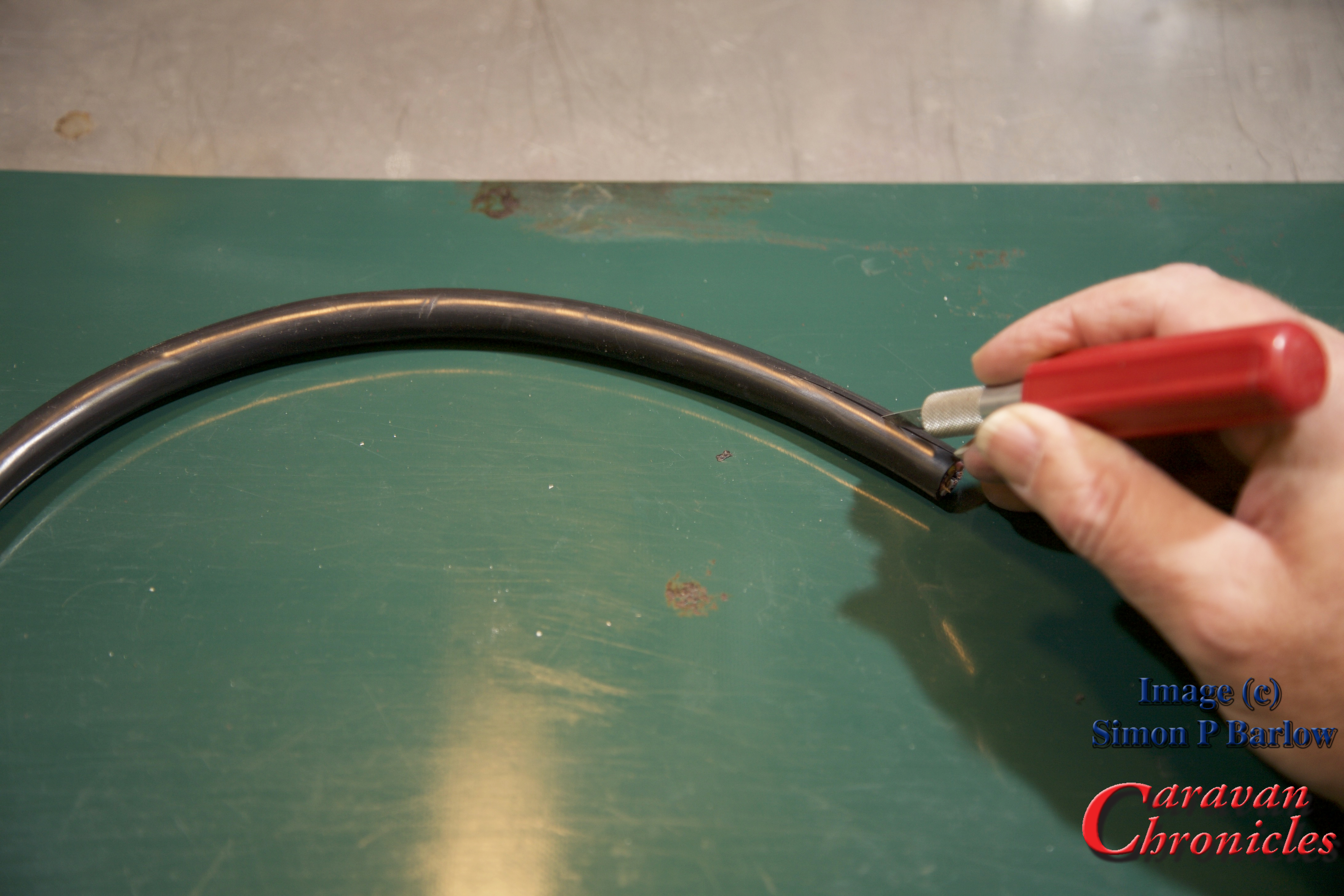
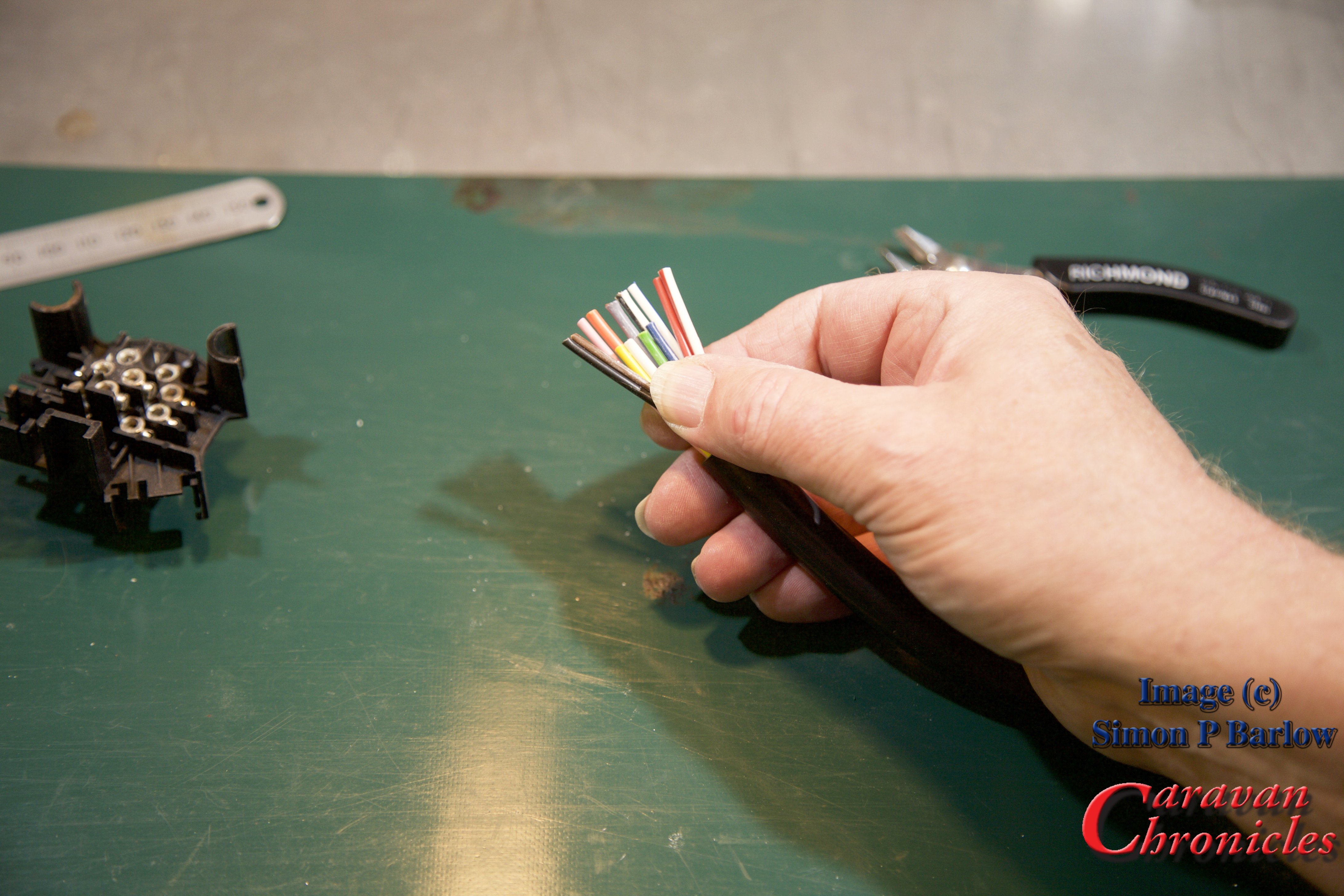
The first step is to trip back the outer cover for the cable. Strip back enough so that the individual cables are long enough to trim to length:
The next thing to check is have you got the right end of the cable? The cable manufacturers lay the individual conductors in a specific pattern so that when stripped, the pattern of colours is in the right order for the end you are terminating. If you have the incorrect end of the cable you will have to cross all the colours over each other to install them correctly in the plug (or socket) As you can see, this is the wrong end for a socket:
Ok, I’ve stripped the other end and you can see the colours are in the right ‘order’ for terminating a socket:
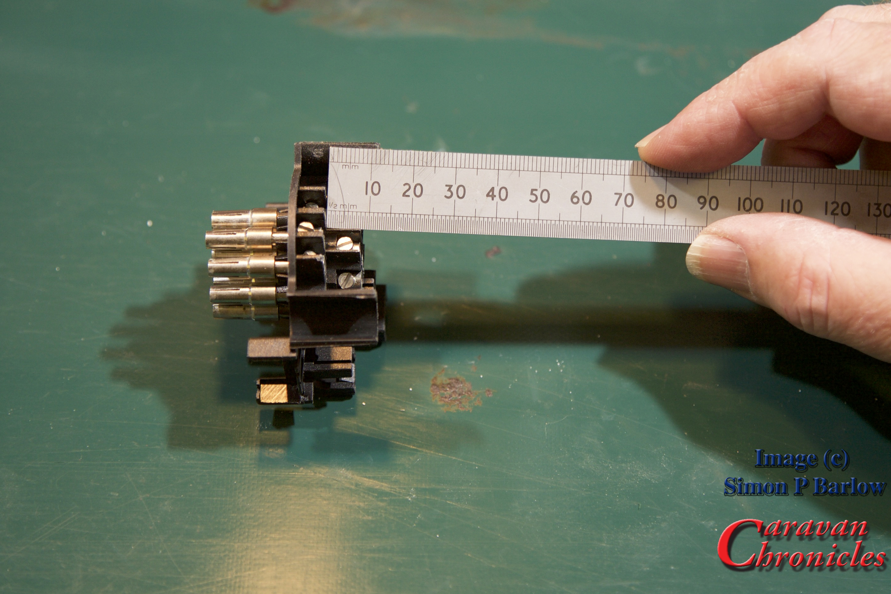
Next we need to measure the difference in termination length between the four centre line and the 9 outer pins… here it’s about 8 mm:
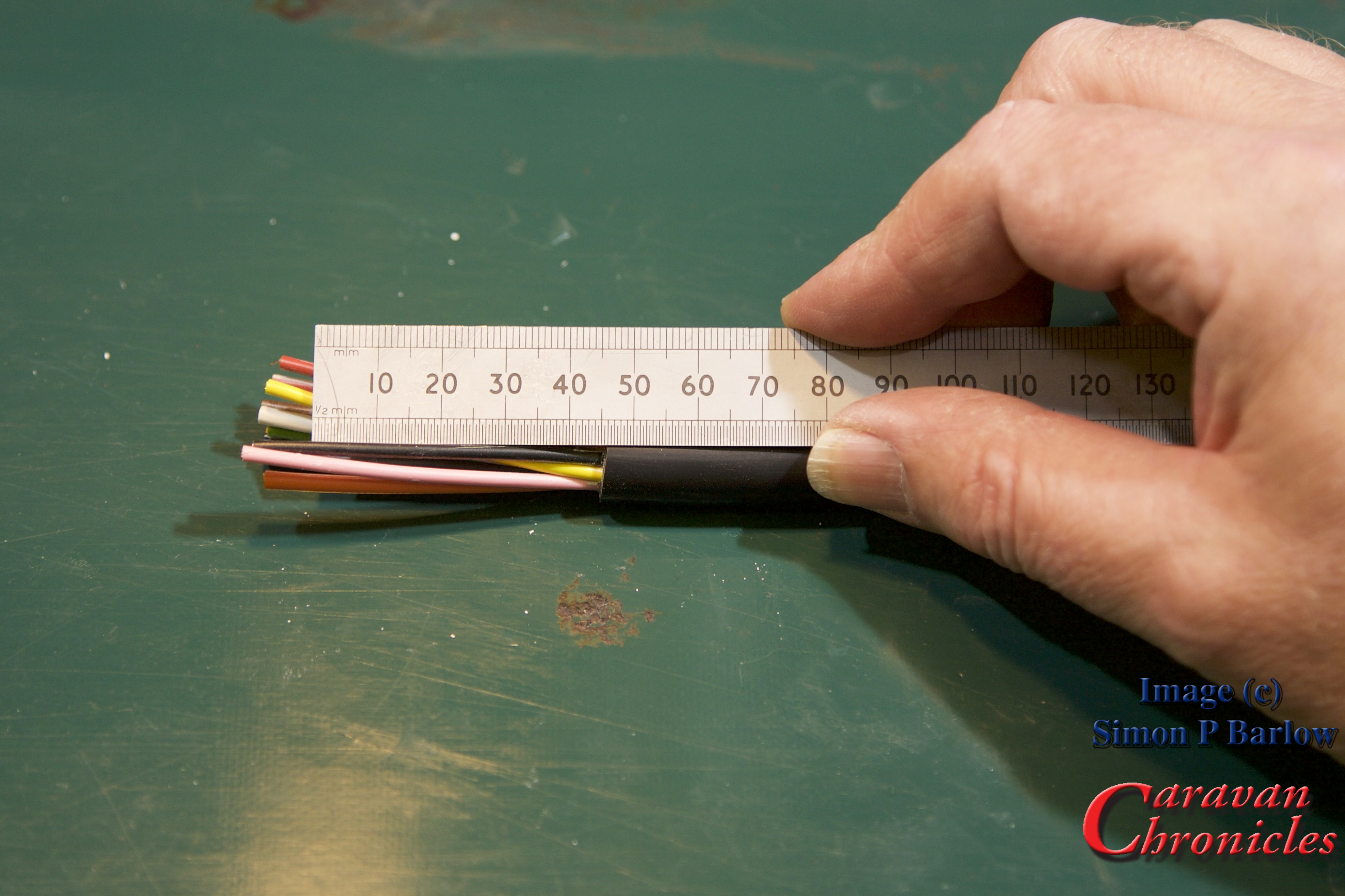
Measuring the back waterproofing cover I know the outer jacket needs to be a maximum of 45 mm from the 9 outer pins and the 4 inner pins need to be trimmed back to 37mm:
Now the cable is cut to the right length so there should be no short or long cables causing problems when assembling the socket:
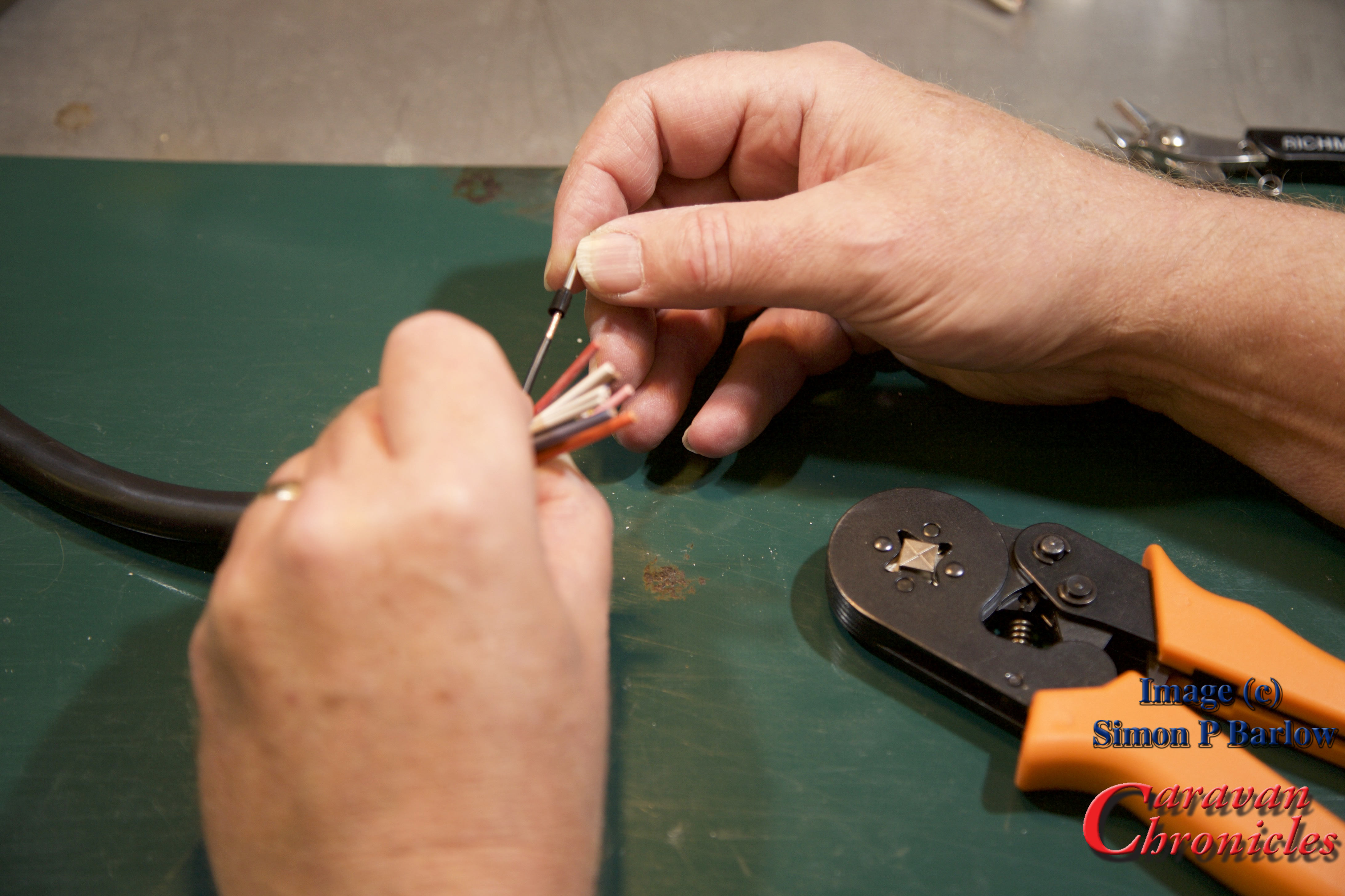
Strip back the individual cables so the exposed conductors are the same length as the ferrules:
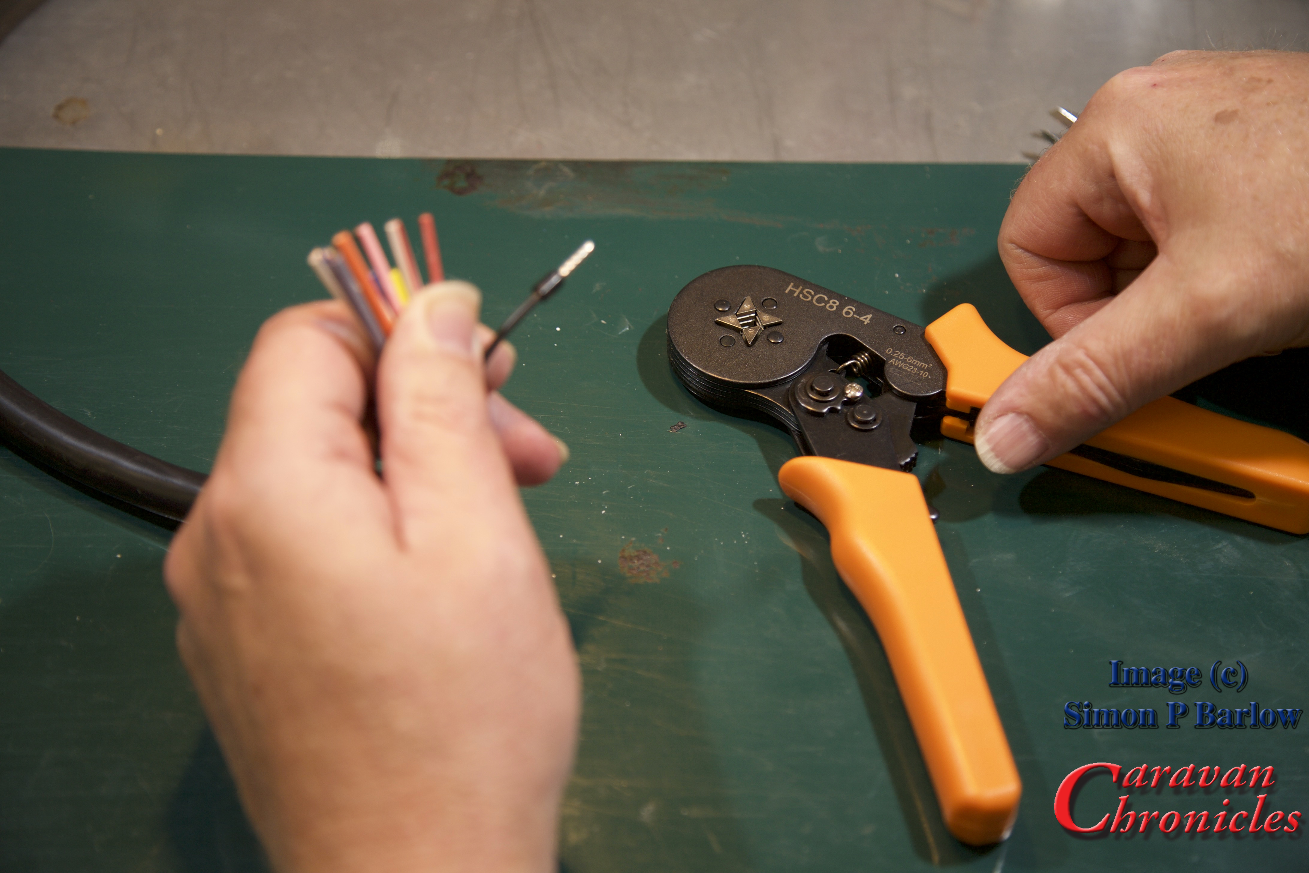
Slide the correct diameter ferrule on to the exposed conductors:
Crimp into place:
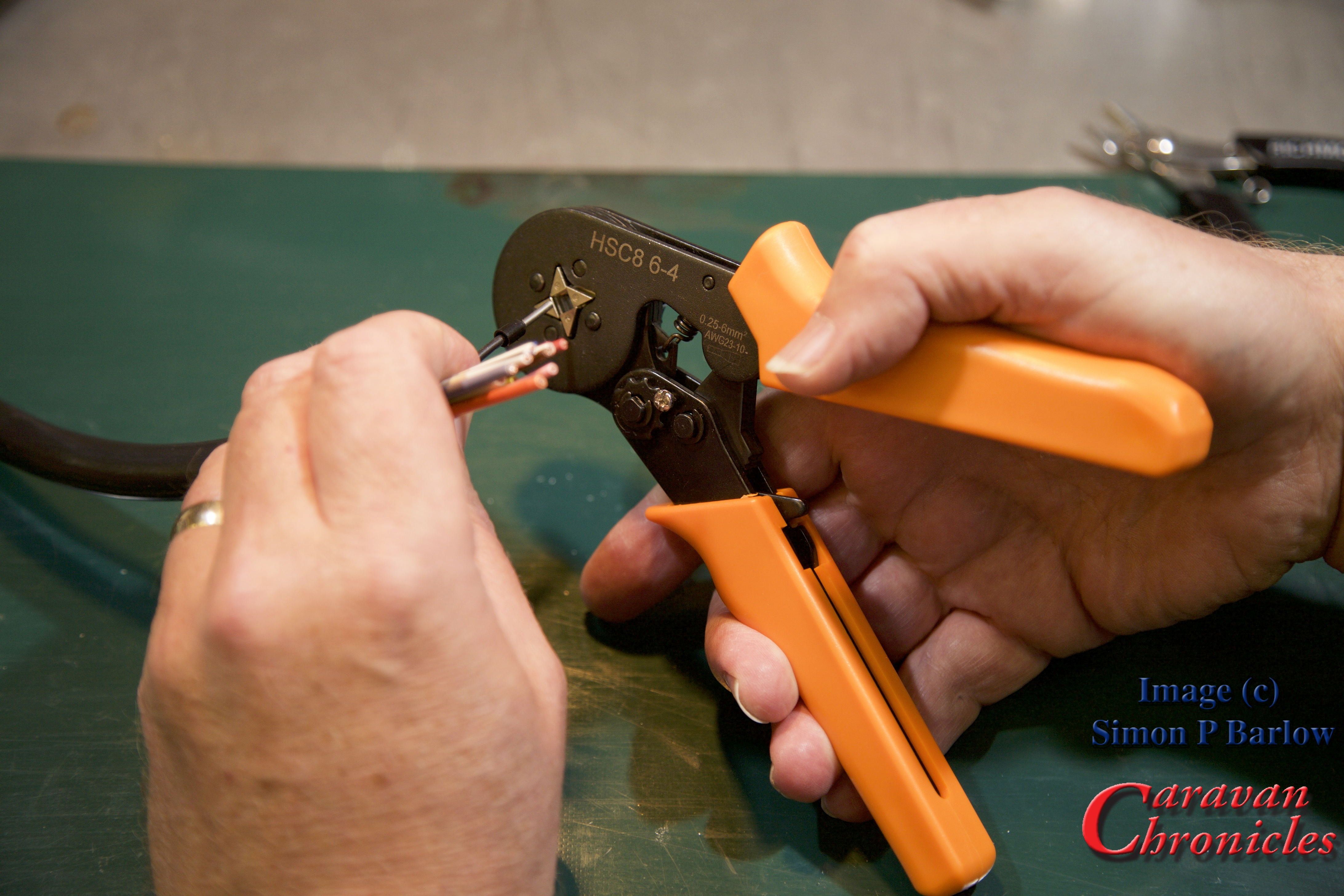
The crimp tool is set so that it will only apply the correct pressure to compress the exposed conductors the required amount. Squeeze the handles and the four jaws close on the ferrule and compress it, continue squeezing and once the jaws have attained the right pressure the ratchet mechanism in the handle releases.
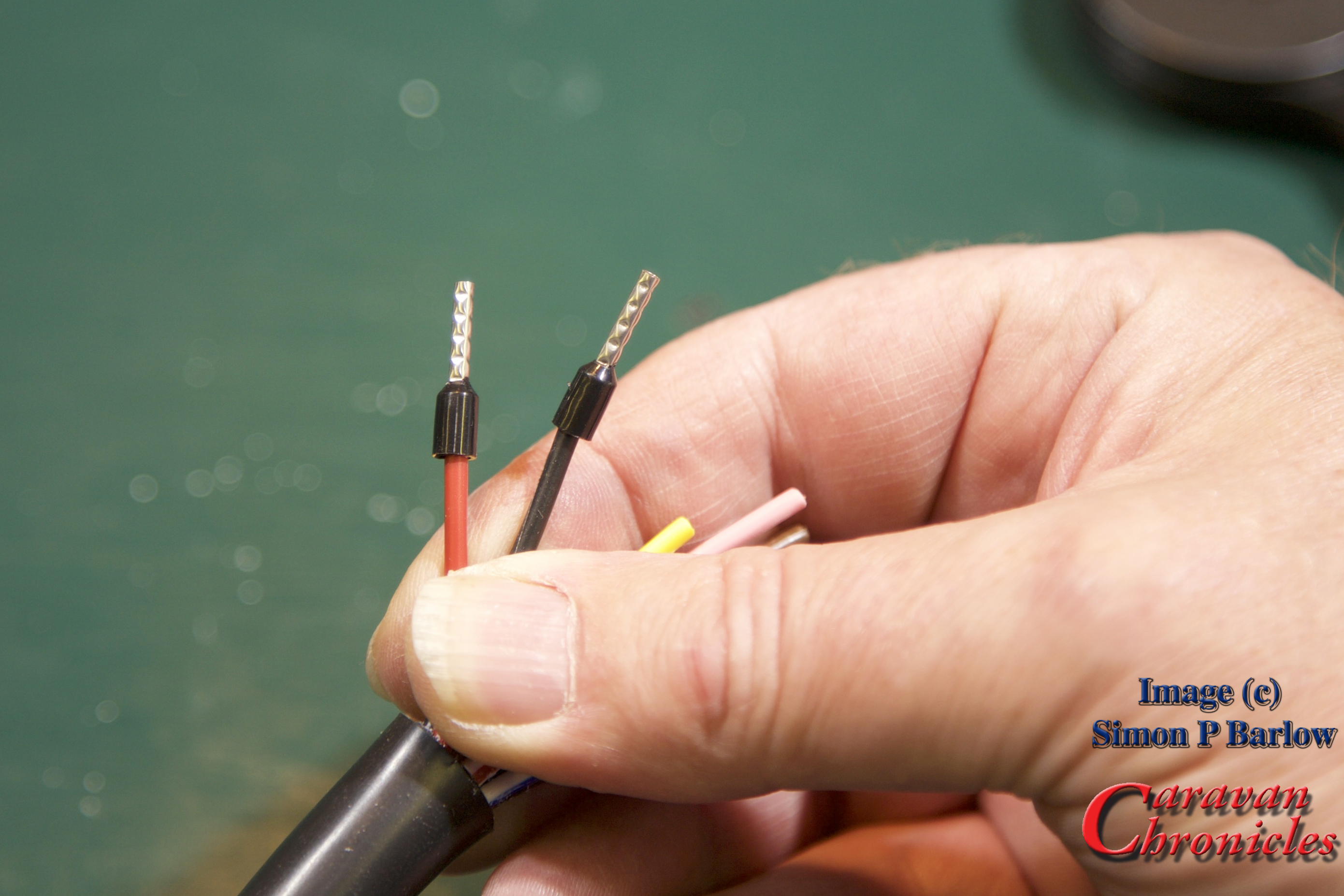
If you look at the picture below you will also see that the crimp tool also presses several ridges into the tube, this is to increase the mechanical grip on the conductors and help stop the tube distorting under the pressure of the terminal screw tip:
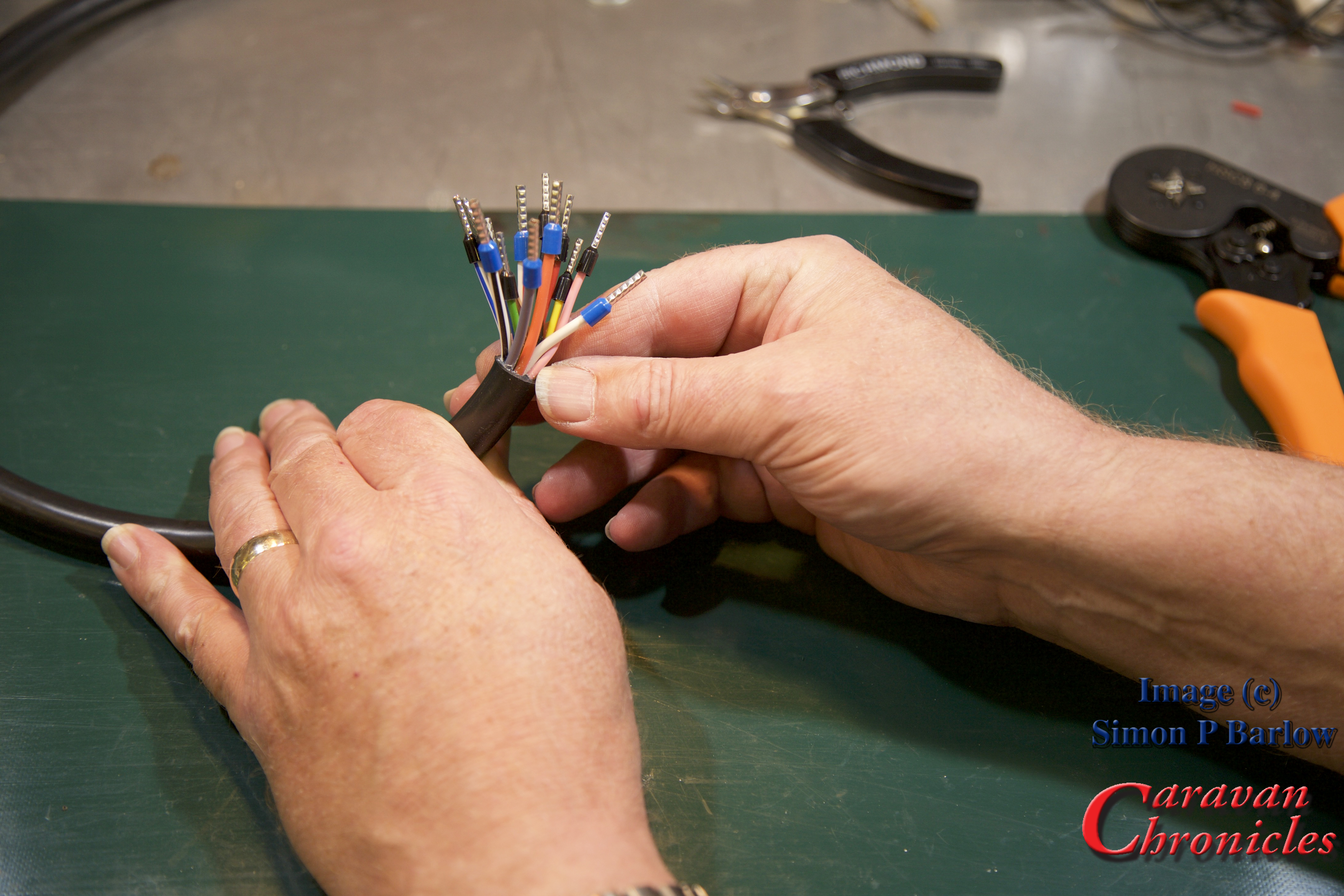
Continue until you have all the cables completed:
One last check… look for stray strands and anything that doesn’t look as though its crimped correctly… give them the ‘tug’ test if in doubt.
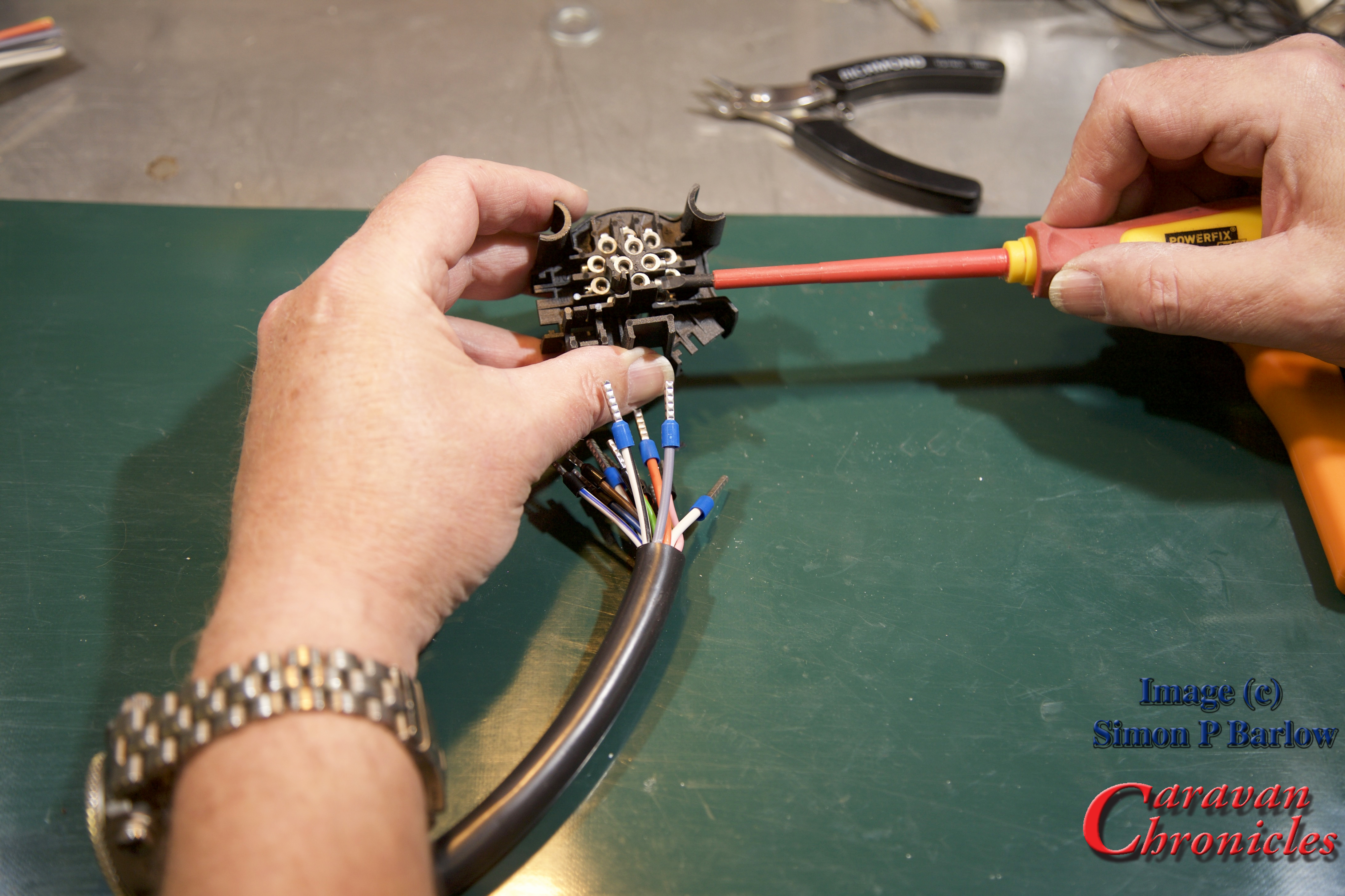
I always like to back off the screws so the ends are just visible in the holes:
The next thing you might need to do is correct the length of the ferrule. I have used standard length ferrules and as the holes in the socket terminals are not as deep, I had to trim off the excess. The ridges pressed into the ferrule body help gauge how much to trim off. In this case I only had to snip off to the first indent:
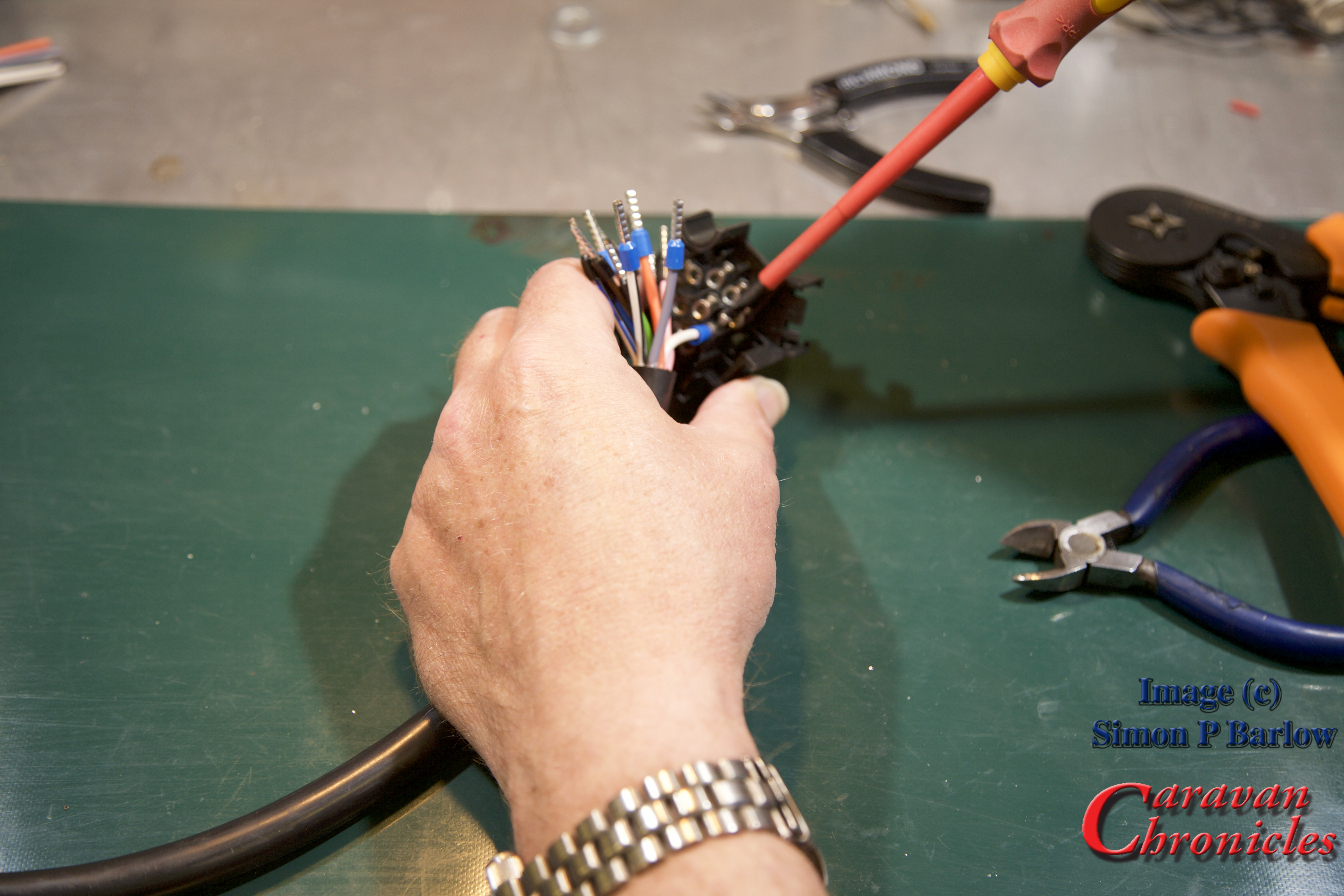
Once trimmed to length, it’s a simple matter of following the colour coding and inserting each cable and tightening the screw. I always start with the four pins in the middle:
Once all the cables are terminated, have a good look to see if all the screws are tight, and of course check the colours are in the right place!
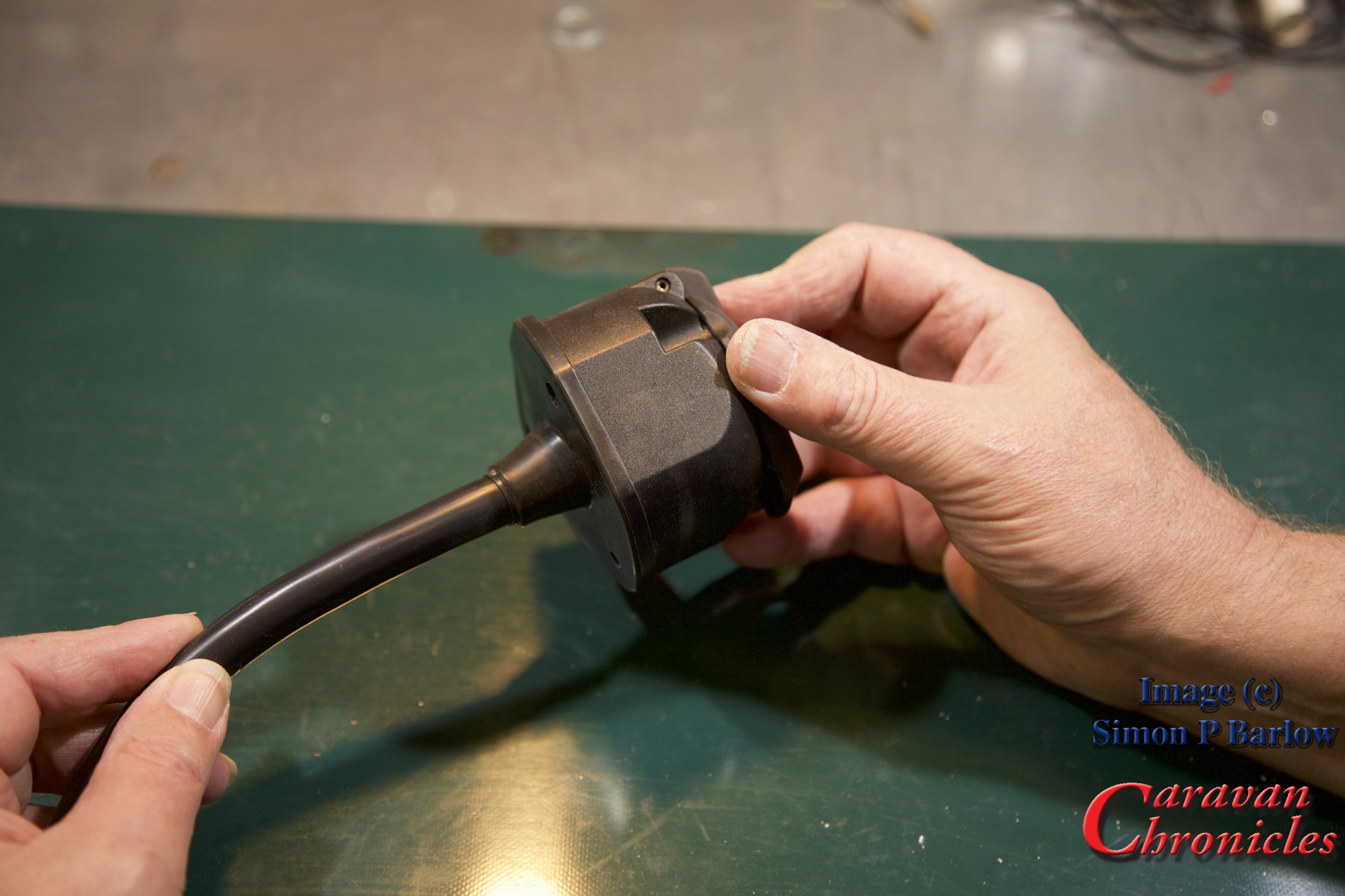
Because the cable was trimmed to the right length before we started there are no loops, so the cover can slide on neatly:
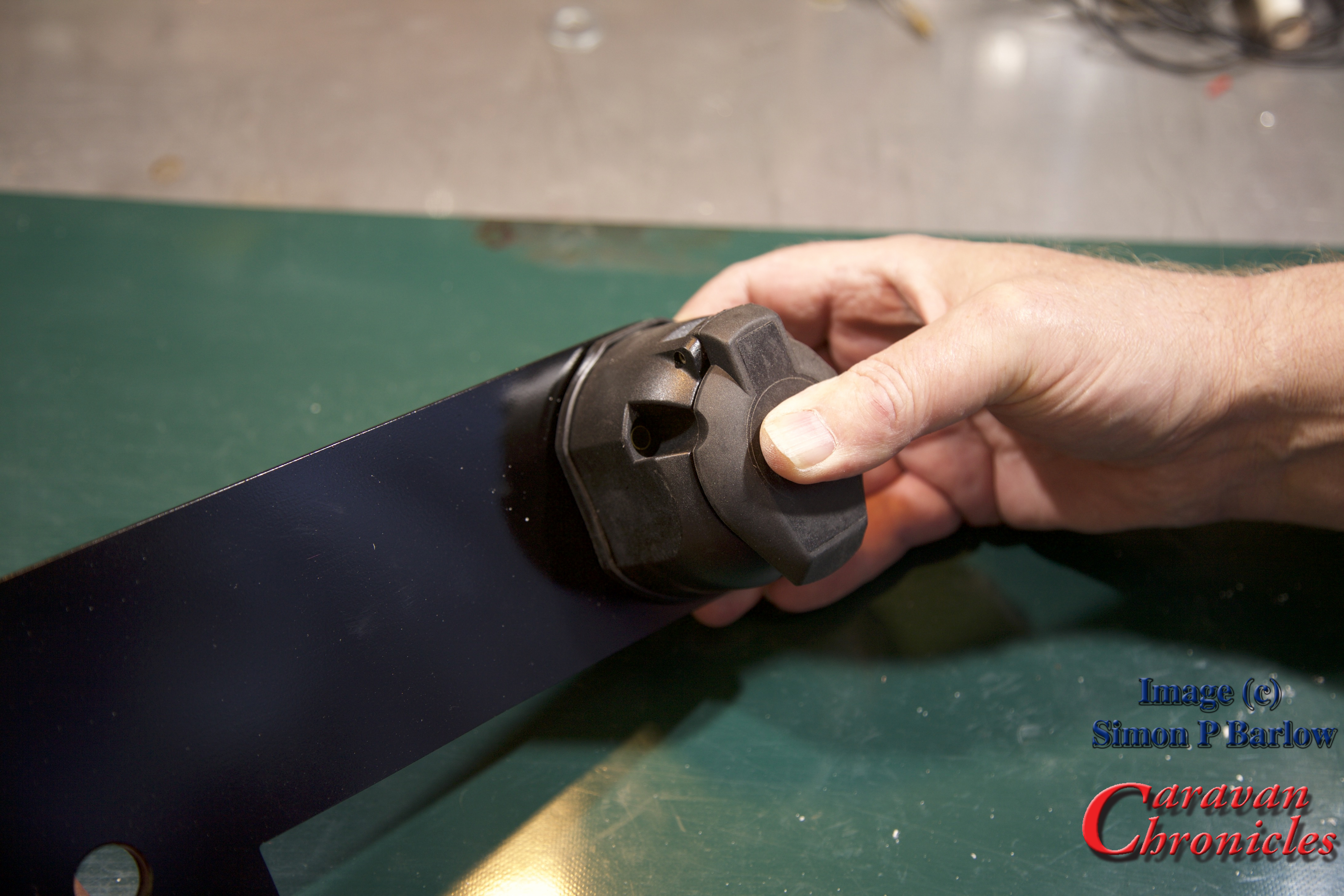
There we go, a finished socket all ready to mount onto the bracket:
To terminate the socket from start to finish and while Sue (thanks `Sue) took all the photos took no more than 25 minutes. Ok it was on a bench and doing outside at the back of a vehicle will take a bit longer, but it’s not that difficult to get a professional result.
The ‘Compromise’
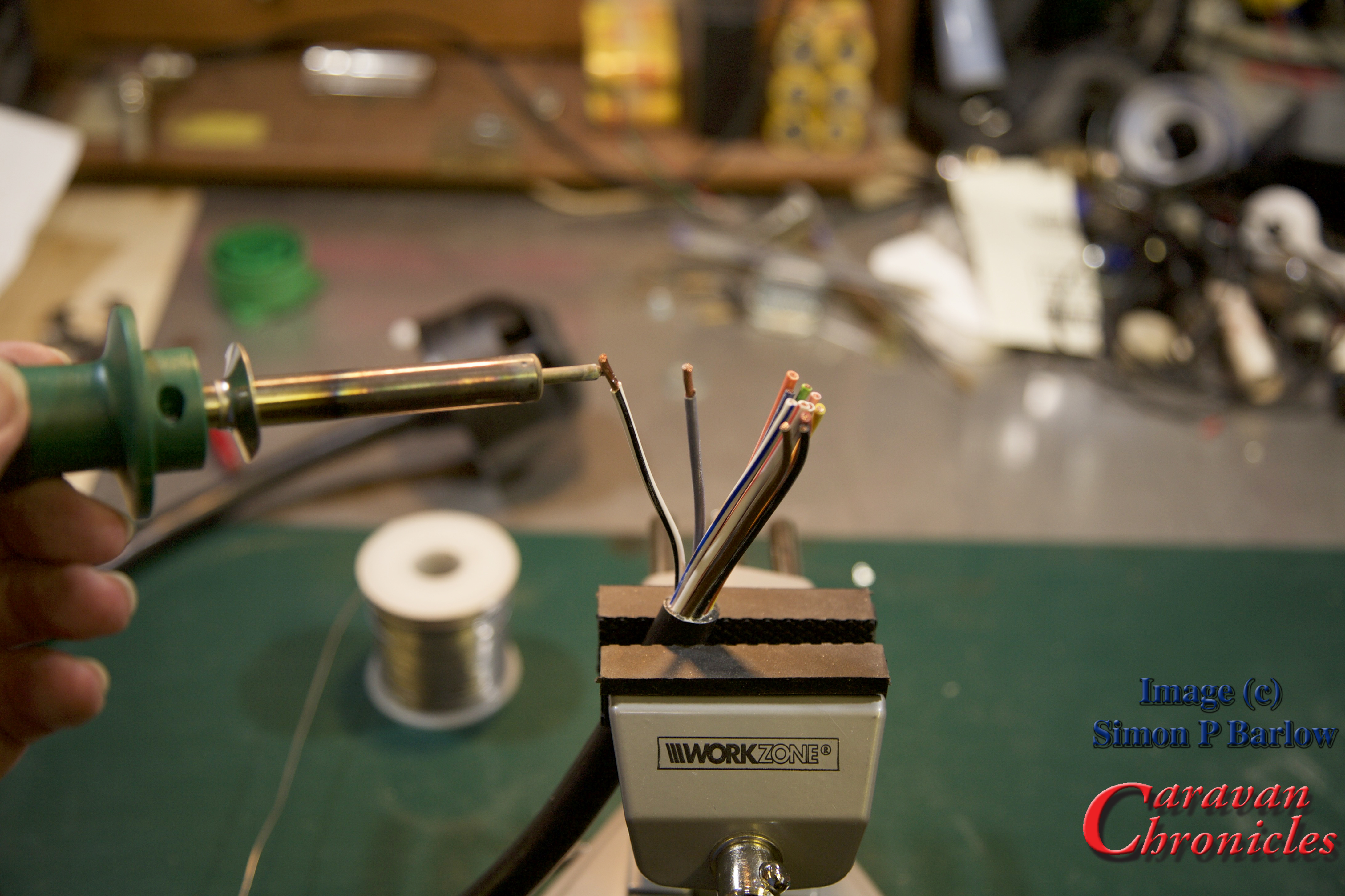
Right back at the start I said there was a compromise – soldering. It’s not difficult to do and achieve and end up with a professional result.
Practice makes perfect and its worth having a go on a scrap length of cable first.
Here’s a few of my tips for successful soldering:
Don’t apply too much heat to cause the insulation to melt (turning down the temperature of the soldering iron or reducing the contact time between the soldering iron and cable helps)
Don’t try to melt solder onto the tip of the iron and run it in to the cable you will burn off the flux too fast… instead touch the solder onto the hot strands of the conductor. Capillary action will pull solder into the strand bundle.
Don’t allow too much solder to be drawn in. You are looking for just enough to still be able to make the outlines of the strands of cable, not a big ‘blob’ of solder on the end.
The solder should look shiny not dull. If it’s dull, the solder cooled too soon as the conductors were not hot enough, this is commonly known as a ‘dry joint’ the solder sits on the surface of the copper.
Avoid breathing in the fumes given off from the flux and the solder. Solder is an alloy of tin and lead… and the flux is pretty nasty too. ( I have an old computer cooling fan that I use to blow the fumes away if I’m doing a lot of soldering).
If you have made the soldered cables too long, you can always trim them back to the correct length. Soldering all the conductors in a caravan cable like this usually takes me no more than five minutes from start to finish.
A few practice runs will soon get you producing good results.
Finally to finish off, I usually give the finished connections a spray of ‘liquid plastic’. It comes in an aerosol can and when sprayed on form a thin plastic coating over everything. You can usually find it in motorbike and automotive shops for waterproofing electrics and HT leads.
It easy to get a good professional result, and I still can’t understand why some tow bar fitting companies don’t either crimp or solder their connections. They usually do when it comes to connecting the other end of the cable to the vehicle. The cynic in me wonders if they are hoping for repeat custom when sockets or plugs start to have problems in the future.
I have been asked where you can purchase some of the products featured above. Here are the links to the products in the Amazon store. If you click on the links and purchase the items, a few pennies will go to helping the cost of running CaravanChronicles.com
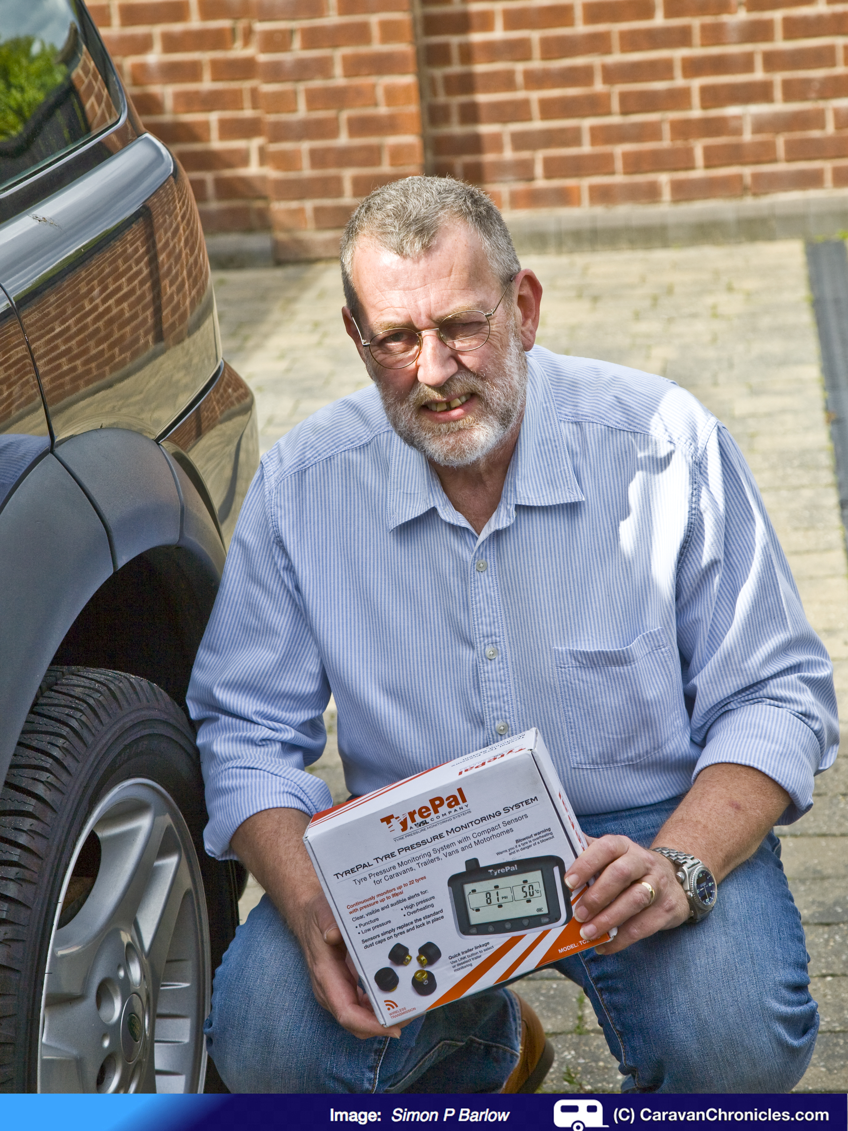
If you are a regular reader you may remember that on our last trip out we had a bit of an issue with tyre pressures with the caravan (“When Things Don’t Go To Plan…”). Well, a few days ago I was contacted by Charlotte from Wheel Solutions Ltd the people who make Tyre Pal – the tyre pressure monitoring system, asked me if I’d like to test out and review one of their pressure monitoring systems.
With the recent trip still in my mind and especially the difference that just 10 PSI can make in the towing experience I jumped at the chance. Charlotte arrange for one of their TC215B units with 6 sensors to be delivered on loan for a few weeks while we try it out on our next trip. From saying “Yes”, the package containing the TC215B unit, mounting bracket, charging lead, accessories and sensors arrived the following day.
So, this weekend I’ll mainly be unboxing, evaluating and installing the unit and sensors and posing about the install and setting it up which, from my brief scan through the comprehensive user manual, looks like it’s going to be a breeze.
In a few days time we will be setting off for Plough Lane Caravan Site, one of the Tranquil Touring sites and I’ll report back on how it performed on the trip and giving my thoughts about it.
Now, “in a bit of an exclusive” (I’ve always wanted to say that!) for Caravan Chronicles we will have a special offer from Tyre Pal at the end of the review… just in time to get yourself an early Christmas present… so keep checking back.
One of Caravan Chronicles long time readers and supporters, Colin “Snowy” Snowden, has sent me an excellent article he has written covering all aspects of upgrading pre September 1998 UK caravans to the 13 pin Euro Plug.
It’s very comprehensive article and goes into detail about the various problems and colour codes that were used and cover some of the changes that are required, habitation relays and details the steps required to actually do the upgrade with steps on fault finding.
If you have a pre September 1998 caravan and are thinking of replacing the original 12N/12S wiring with a 13 Pin plug, it’s an essential read.
Colin has included contact details in the article, but if you have any questions that the answers might be helpful to others as well, you could also post them in the comments section below and Colin will be able to answer them.
A couple of days ago one of Caravan Chronicles readers, Vic, posted in the comments section of “Understanding Caravan and Tow Car Electrics” that he recently flattened his car battery by leaving his caravan connected to his car. Here’s what he posted:
Hi Simon, while travelling across Spain I made an overnight stop and left the caravan connected to the car electrics I also hooked up to mains. The next morning the car battery was flat, I’m sure I’ve done this before with no consequence. All I can think is that european site wiring can be suspect.
brilliant article.
OK, that got me thinking…
Was it the car-off-van switch faulty? Was there another fault of some sort? I asked Vic for the details of his caravan and he replied it was a 2009 Bailey Senator California. I don’t know the exact details for Bailey electrical schematics, but it should not be too difficult to work out what might be happening. I started to think of various failure scenarios that ‘could’ account for Vic’s problem. At this point I have to say I’m indebted to David Rose for sending me information about the electrical services in Bailey Caravans.
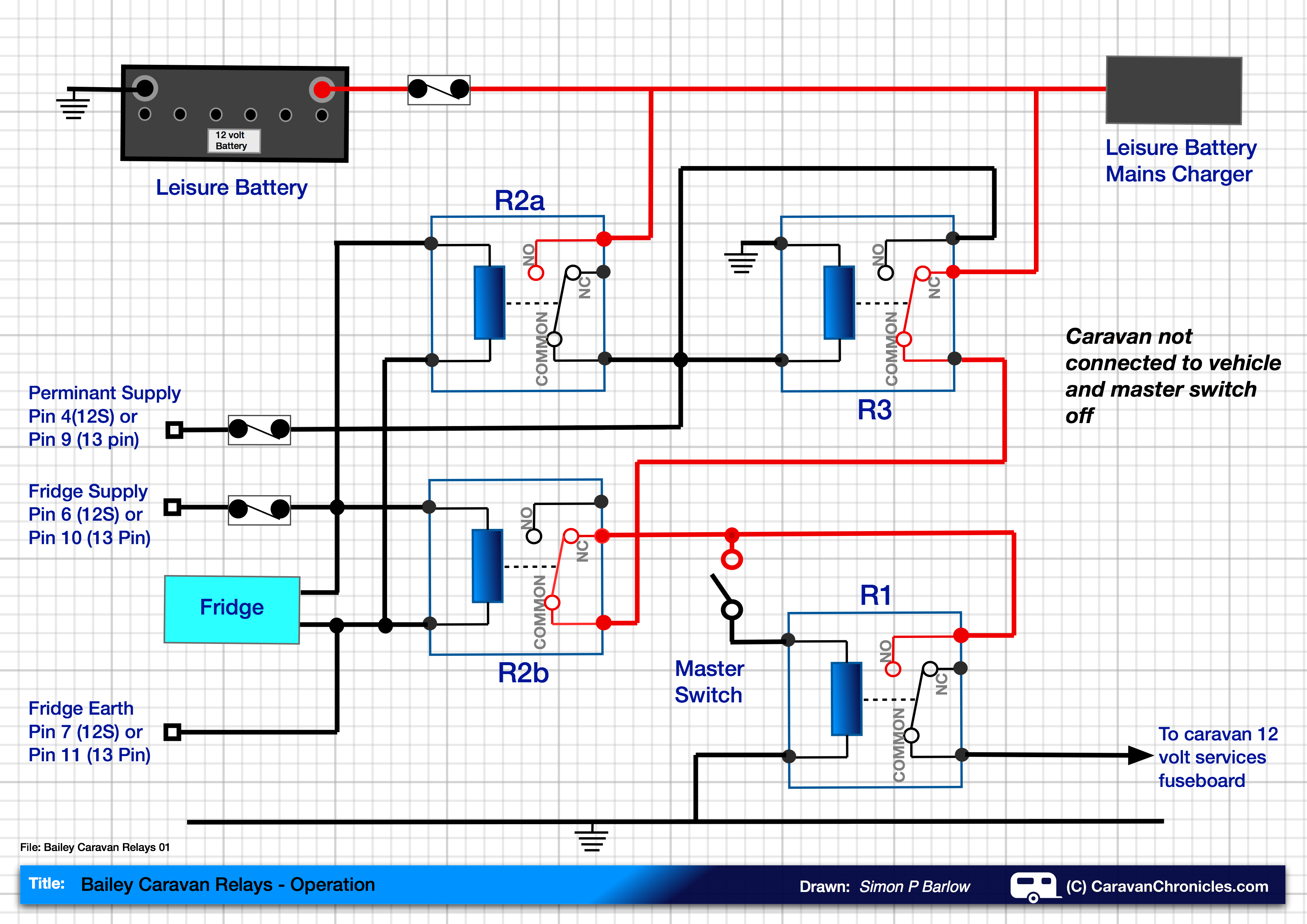
Looking closely at the schematic of the control unit, it all hinged around the correct operation of four relays. Here is the schematic I have drawn out in a simplified form:
The drawing (above) shows the four relays – R1, R2a & R2b, R3 as they are set when the caravan is not connected to the vehicle and the master switch is off. The red lines show what part of the circuits are live. The master switch controls relay R1 and when energised by turning the Master Switch on allows current to flow to the caravans 12 volt electrical system via the 12 volt fuse board.
Above: We have now turned the Master Switch on and can see that relay R1 has energised and is allowing current to flow to the caravans 12 volt services. The caravan is not connected to the tow vehicle.
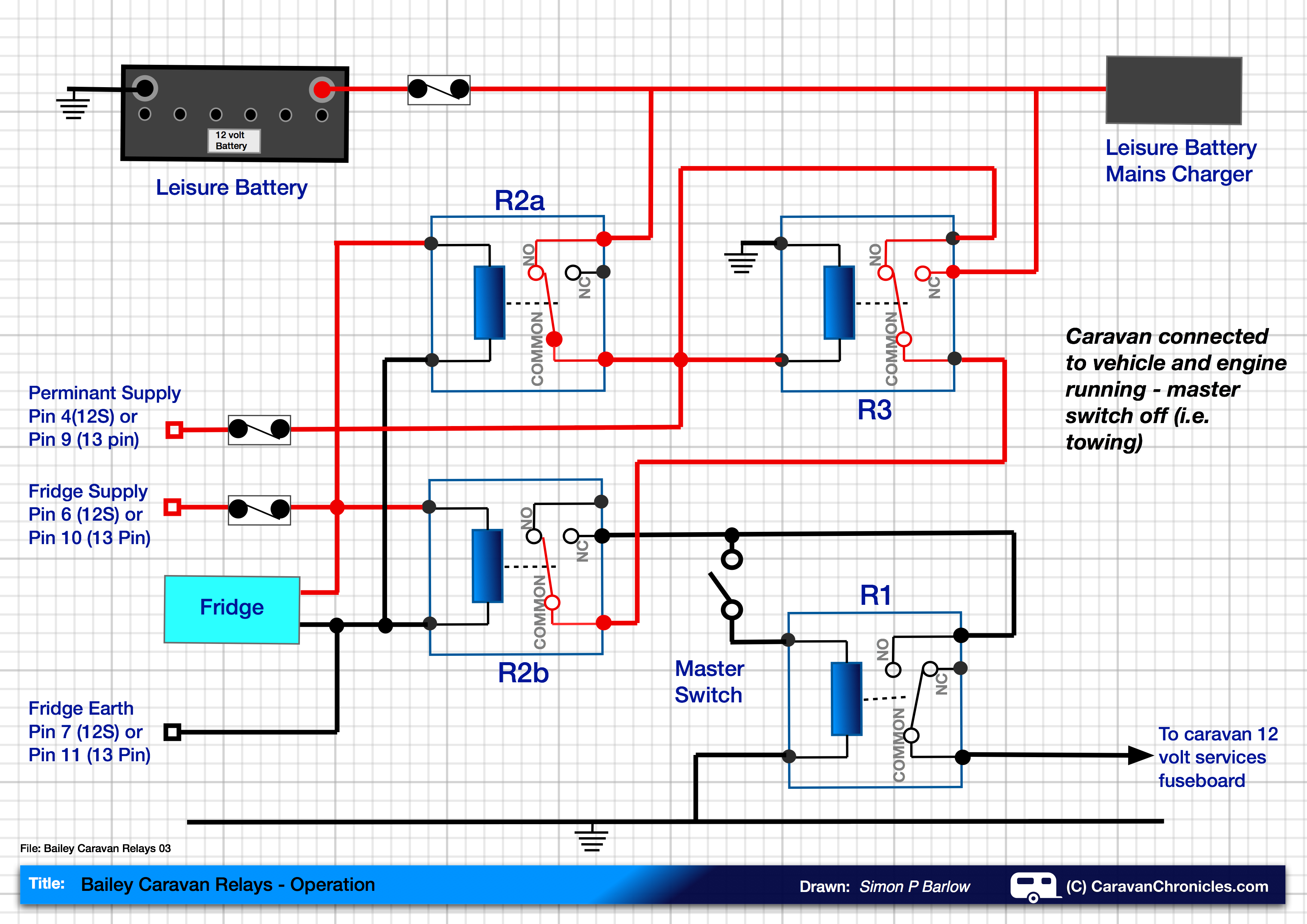
Above: The caravan is now connected to the tow vehicle and the engine is running. The caravan master switch is off. With the fridge circuit powered from the running engine, it energises R3, R2a and R2b. Relay R2b disconnects the master switch circuit so that it cannot operate R1. Relay R2a connects the leisure battery to the 12 volt permanent feed from the tow vehicle. R3 energises, but only switches the feed for the master switch from the leisure battery to the permanent 12 volt supply from the tow vehicle. As this stage it cannot be used to supply the master switch due to R2b being energised.
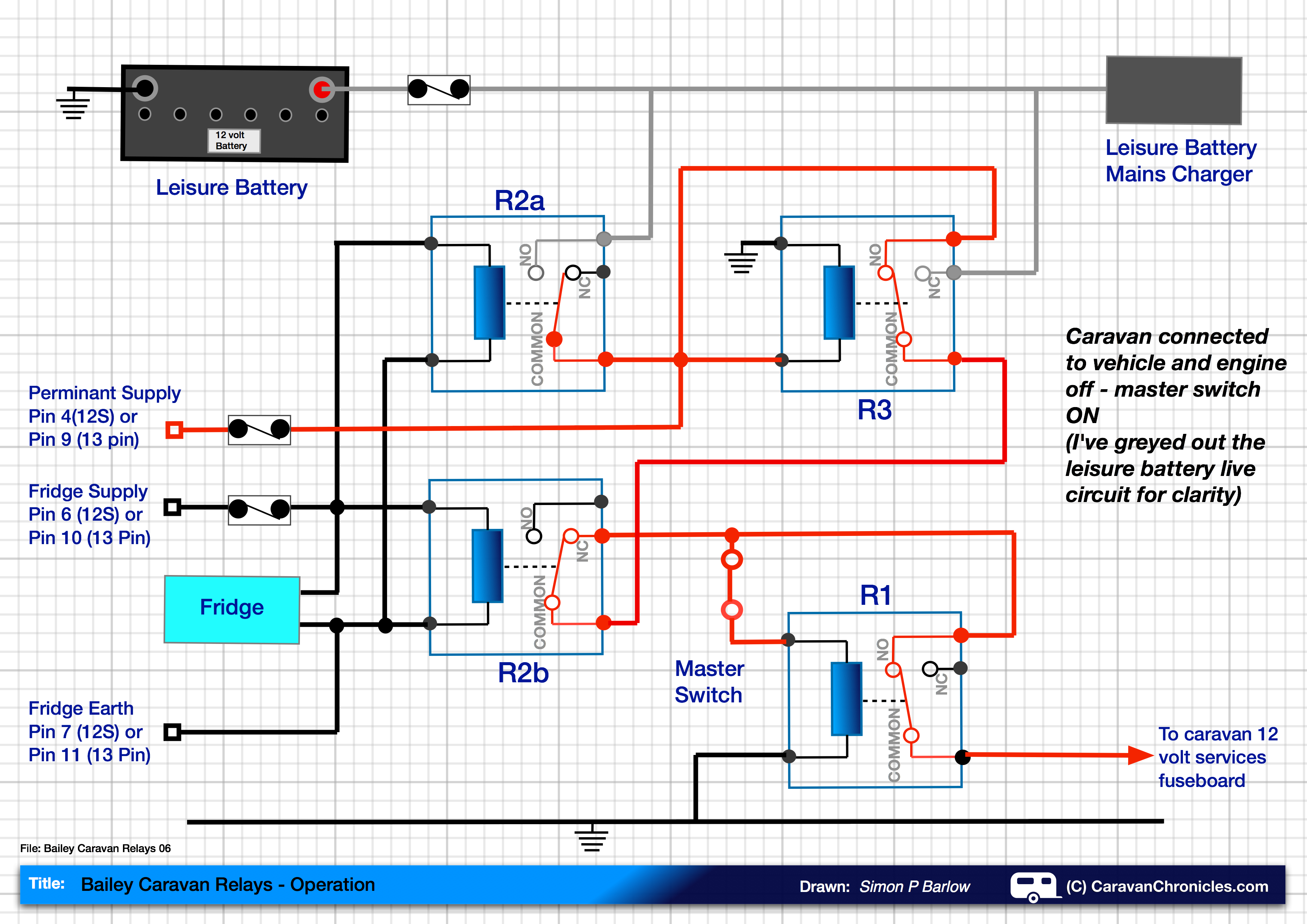
Above: The caravan is still connected to the tow vehicle, but the engine is off. Relay R2a and R2b that are controlled by the fridge circuit are now not energised and revert to the default position. However as the caravan is still connected to the tow vehicle, the 12 volt permanent feed keeps relay R3 energised, therefore supplying the Master Switch – not from the leisure battery but from the permanent 12 volt feed from the vehicle.
This now leaves us in the following position:
Above: The caravan is connected to the tow vehicle but the engine isn’t running. The master switch is on. The caravan now receives it’s 12 volt feed from the tow vehicle to power all the 12 volt services. I have greyed out the live circuits from the leisure battery. Even though the caravan is plugged into a EHU bollard, the 12 volt services will be run from the vehicle battery and not the mains charger/ leisure battery circuit. The fridge will continue to work on 240 volts as will any mains powered equipment.
So, it’s not a ‘fault’… it’s a ‘feature’ ! Leaving the caravan plugged into the car and turning the Master Switch on allows you to power the caravan’s 12 volt services from the car. Disconnect the lead from the car and the caravan will be powered from the leisure battery.
If you around the Nottingham, Mansfield or Grantham area Lodge Farm Leisure are now fully equipped to refill you Safefill, Gas-It or Gaslow systems having recently installed their own LPG refilling equipment. Chris and the guys have probably beaten all the other caravan servicing and even caravan dealers by being the first to install this equipment. With the increasing cost of conventional bottle exchange and the recent recall by one supplier of some of their cylinders it makes sense for caravanners and motor homes to move over to a refillable system. Currently their price for LPG is 65 pence per litre and they are aiming to be 5p per litre cheaper than other stations in the area, which is great news!
We have been using Safefill since we started caravanning and have easily covered the cost of the cylinder. With more and more caravans and motor homes now coming equipped with state of the art solar panels, moving over to a refillable gas system makes the task of planning ‘off grid’ stops so much easier as you can always start your trip with a full tank of gas and top up if required!
I’m sure in the coming months other caravan service centres and dealers will try to play catch up with Lodge Farm Leisure… in the meantime if you are in the area, you now know where to get a fill up.
Directions to Lodge Farm Leisure are on their website.
That is one of the most common questions that I am asked about road light problems with caravan’s and trailers. Others are::
“Why do my side lights come on when I brake?”
“When I turn my side lights on why do the indicators glow dimly?”
“When I put my side lights on why do my reversing lights come on?”
“When I brake why do all my rear lights come on?”
The answer is fairly simple, and a lot of people will tell you “It’s an earth fault” So often said simply because they have heard someone else say it but really they don’t understand how it can be an earth fault. Trying to find a fault even if you know what it is can be frustrating if you don’t know a bit of theory behind it, but I’ll try to give you an insight into what’s going on. Lets have a look at a basic wiring diagram for the caravan or trailer road lights and their connections.
The term ground and earth are basically the same thing but the ‘earth’ refers to the cable and the ground is the termination of the earth cable to the car in this case.
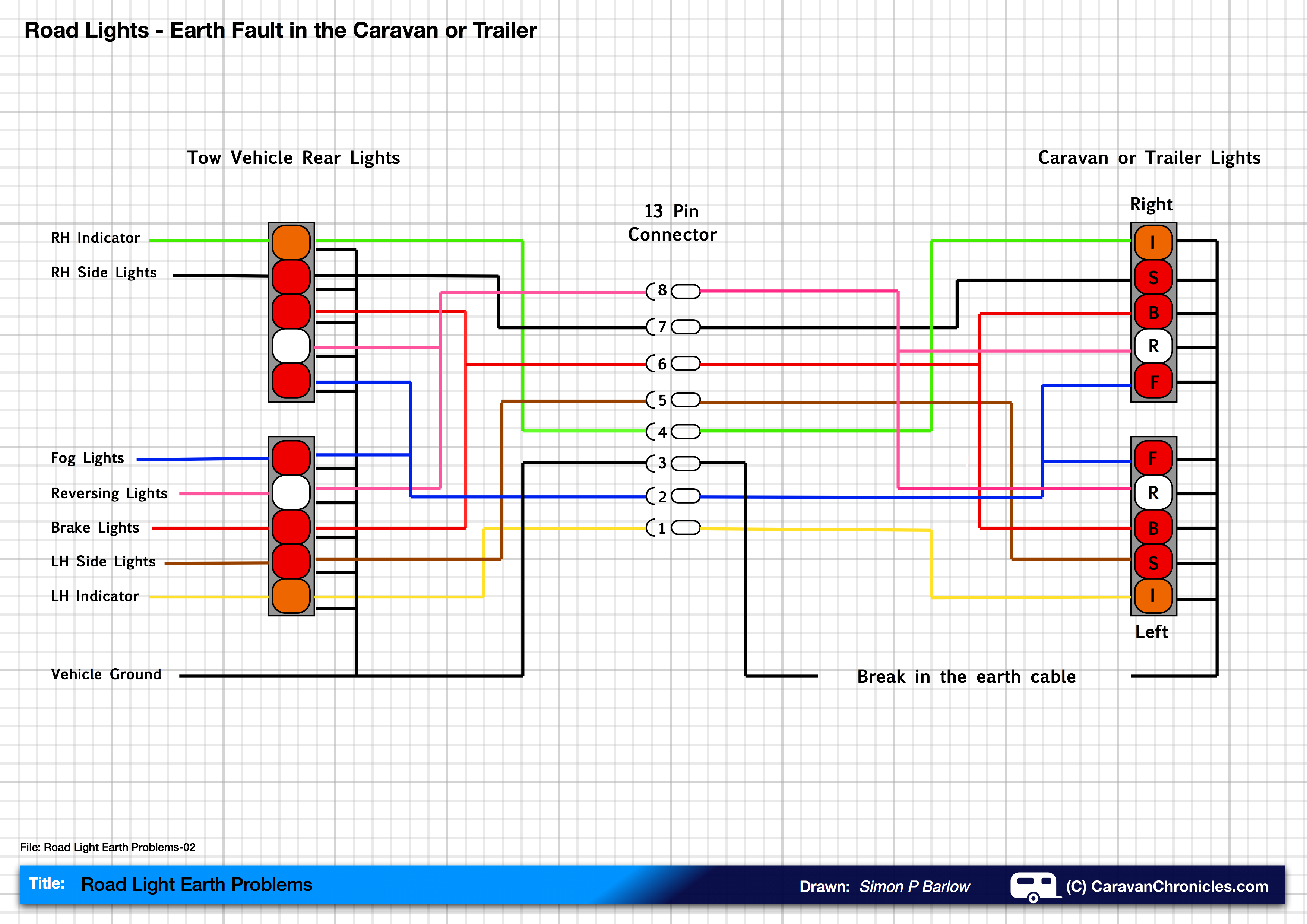
The drawing above shows the basic road light wiring. (Click on the diagram to enlarge it) You can follow each circuit through from the tow vehicle through the 13 pin connector to the rear lights of the caravan or trailer and then back through the return path (earth) to the 13 pin connector and back to the vehicle ground as shown in the diagram.
What happens when you operate the right hand indicator? Electricity flows down the green wire and lights up the right hand indicator on the vehicle and continues down the green wire through the 13 pin connector to the caravan or trailer right hand indicator. It then returns through the black earth wire to vehicle ground.
So what happens if we have an earth fault?
Here is the same drawing only this time with an earth fault.
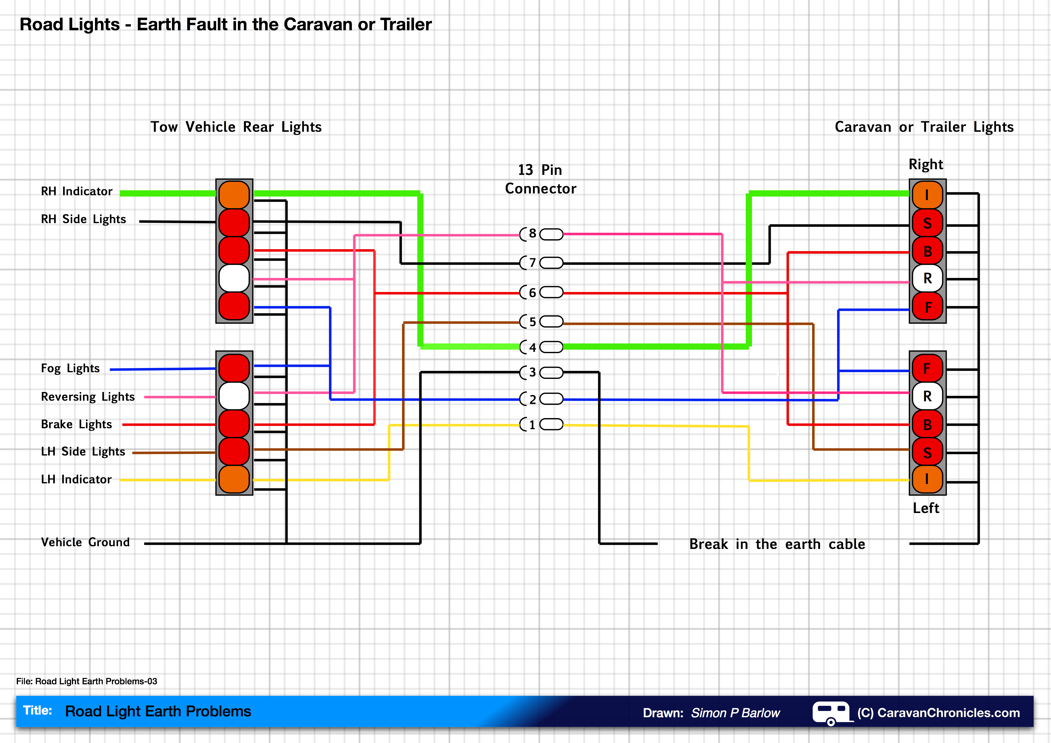
Now the return path for the lighting circuits is broken, but using the indicators now also flashes the rear side lights. So what’s happening?
In the diagram below we have again turned on our right indicator, electricity flows down the green wire (shown a bit thicker this time) to the rear caravan or trailer indicator. It flows through the bulb and should then follow the black line to the vehicle ground. But it can’t as there is a break in the wiring.
Electricity really does like to go home!
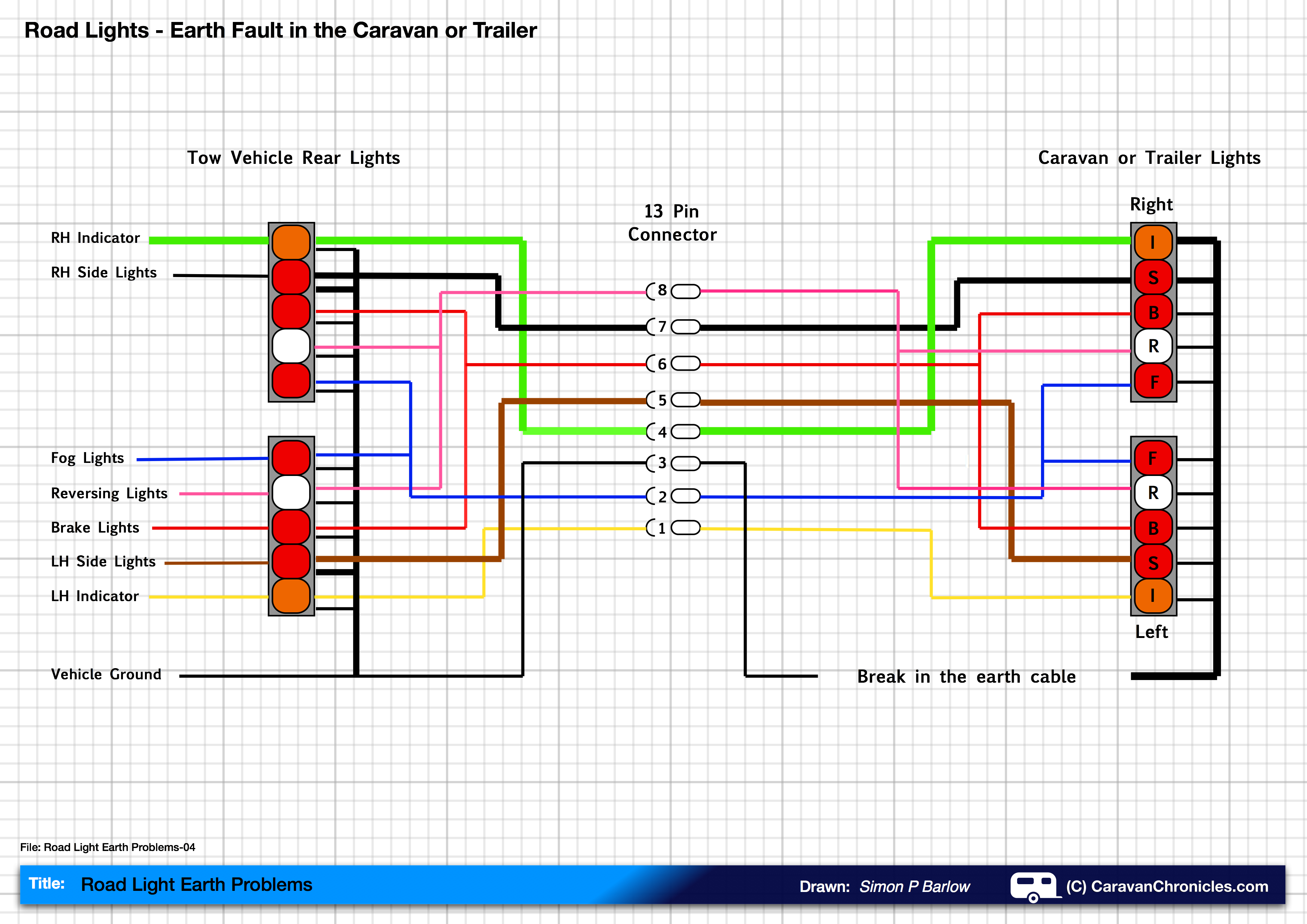
As the return path through the black wire is effectively ‘blocked’ because of the break the electric current will try to find another way home. The only path it can find is back through another circuit, in this case the right hand side light circuit all the way back to the tow vehicle and through the bulb in the rear light to earth, as illustrated below.
So as your indicator flashes, it is also powering the side light on the caravan or trailer and the rear side light of the tow vehicle. Electricity will nearly always find a way home!
But it’s not quite that simple. In the diagram above I have shown one return path (the heavy black lines) but in fact the return path will be through all the light bulb circuits that are not powered. As there are multiple paths back to earth and only one path or circuit powering the indicator bulb, the indicator bulb will be at full brightness but the other bulbs may only be dim.
If you now turn on the side lights and indicate right, the current from the side lights and the indicator will follow the path of least resistance through the other lights that aren’t lit back to the tow vehicle earth.
So the original question of “Why do my side lights flash when I indicate” might now be expanded to “Why do my side lights flash when I indicate? It can’t be because there is anything wrong with the side lights because they work normally”
We now know that the side lights only appear to work correctly.
The diagrams all show a common earth from both sets of rear lights on the caravan or trailer. Sometimes for convenience the manufacturer will run a separate earth for each light cluster, so all the wires for the left hand lights run down the left hand side and all the wires for the right down the right hand side. The common point is usually a small junction box at the front of the caravan or trailer.
If we have similar symptoms as before but only affecting one side (the RH indicator is OK, but the LH Indicator also flashes the LH side light and LH brake light) then the break in the earth cable will be only on the left hand side earth wiring.
So now you know the theory behind earth faults on caravan or trailer road lights. If you want to do a bit more reading you might find these two articles interesting:
One of the questions that I’m asked from time to time is about the 12 volt circuit from the tow car to the caravan that powers the fridge, is how to find any problems that could be the cause of the fridge not working at its normal capacity. There are a few checks that can be done on the fridge first before having to start to look for other reasons why the fridge is not functioning to full capacity when towing.
I have written hopefully a simple guide to checking the circuit tracing the voltage drops and locating where the problem could lie. It will take some time and a basic understanding of how to use a multi-meter is required but it should either help you find the problem(s) or confirm that there is nothing wrong with the wiring and you can stat to look for other possible issues.


 As a temporary mount I used a couple of the small plastic hangars that Fiamma sell that slide into awning rails allowing you to hang things from. In this case a couple of cable ties held it in position. I’m currently in the bat cave folding a small aluminium plate to mount the regulator on that slides into the rail and has a foam padded back to protect the caravan. I opted to use brass fittings for the hose connections rather than plastic just for durability.
 This ‘Y’ fitting has two small ball valves, one of each outlet. So when we go out, I simply turn off the appropriate ball valve. Having a ‘Y’ adaptor also allowed us to fill up our Brita filter jug or draw water off without having to turn the tap off and disconnect the caravan hose. All in all everything worked out perfect. (note I have since changed the blue hose adaptors shown for brass ones for durability).