
As it’s now the ‘off season’ for a lot of caravaners and thoughts turn to sorting out those problems that we put up with on the last couple off trips, I thought I’d look at cable terminations. One of the problems that I’m asked about revolves around cable termination in trailer sockets and plugs. Like most things there is a right way and a wrong way of doing it and there is also the compromise.
So what’s the problem?
Well the problem is terminating a cable to a solid metal part. You will most likely see cables that are striped down to the copper conductors and the individual strands twisted together then inserted in a hole with a screw tightened down to hold the conductors. So whats the problem with this? When you tighten the screw it’s turning obviously and the end of the screw twists down on to the strands of cable, often breaking a few off and pushing quite a few out-of-the-way, usually in an average termination about a quarter of the strands are not held under the screw tip. The 2.5mm square cable you thought would reduce volt drop for the battery charging circuit is now reduced to something less and its current carrying capacity is reduced. Is there a solution?
The obvious one would be to solder the ends of the cable to stop this happening and it’s a great solution, but is does have drawbacks. When you solder the end of a flexible cable the point where the solder stops becomes a weak point and is susceptible to vibration and flexing stress and the thin copper strands transition from being flexible to a solid mass. This is why in aviation, marine and military applications soldering is not usually permitted.
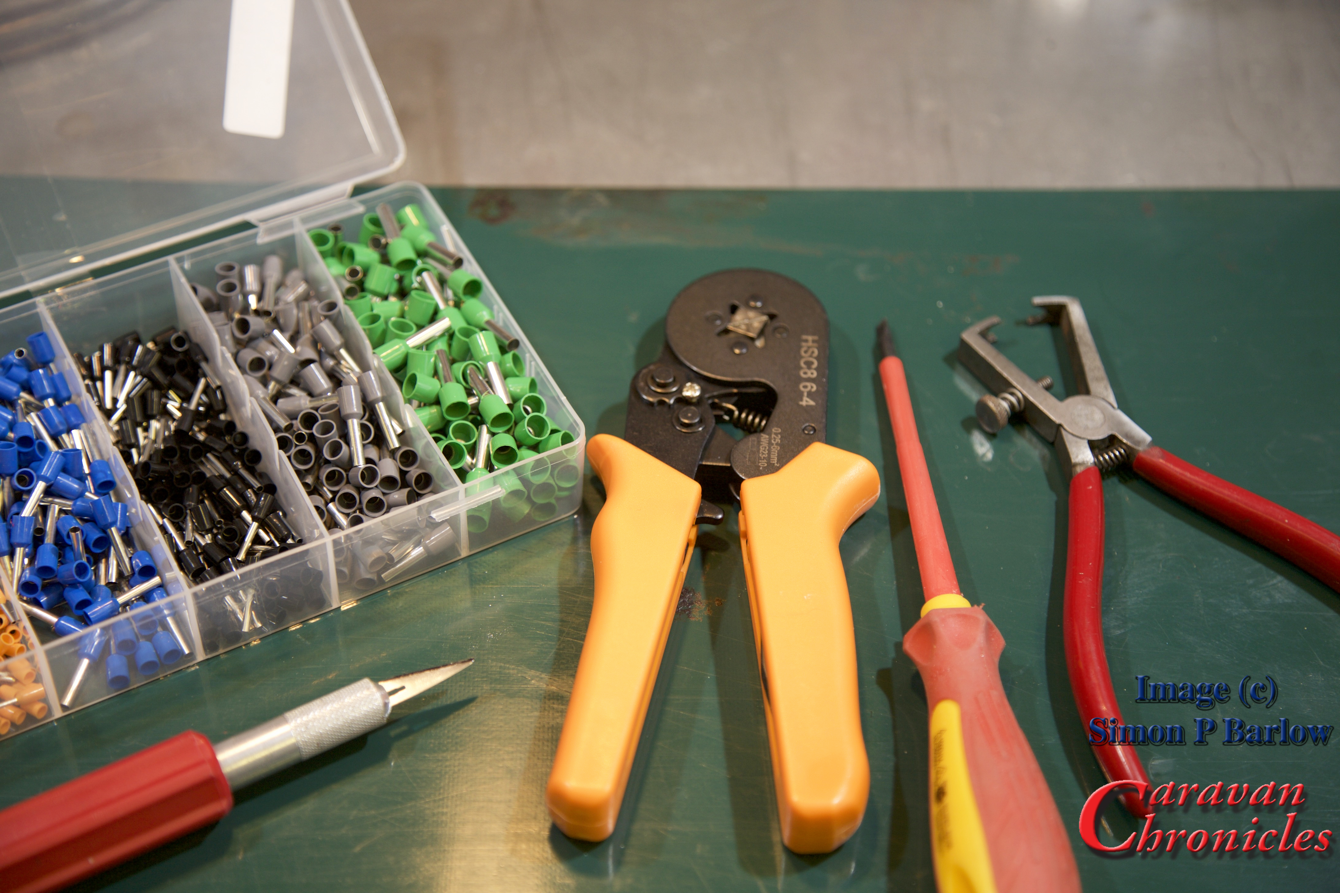
The correct way that flexible conductors should be terminated is by crimping on a “boot lace ferrule”. These are simple brass tubes, sometimes nickel-plated that are slid over the untwisted strands of the conductor and crimped tightly. Some ferrules are just small tubes or ‘U’ shaped section machine crimped and some have a plastic insulator to help isolate the conductor when several are installed in close proximity.
Here’s a simple step by step guide to crimping and terminating a 13 pin trailer socket. It could equally apply to a trailer plug.
For the photos I used a spare socket and short length of standard multi core cable. I have links to all the items, including tools used in the article in “Caravan Chronicles Shopping” at the end.

The tools required are a sharp knife, cable strippers, screw driver, ferrule crimps and the ferrules. (tip: make sure your screw driver is a ‘terminal driver’ with flat parallel faces and if fits snugly into the screw head. As the screws are brass, it’s easy to damage the head using the wrong screwdriver)
The first step is to trip back the outer cover for the cable. Strip back enough so that the individual cables are long enough to trim to length:
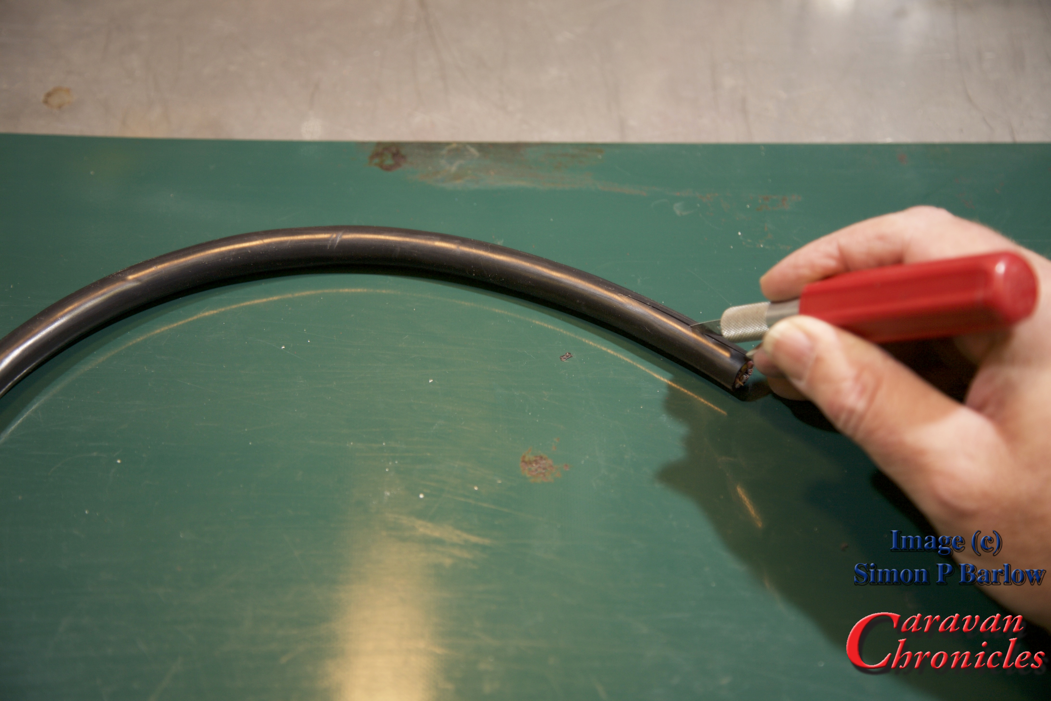
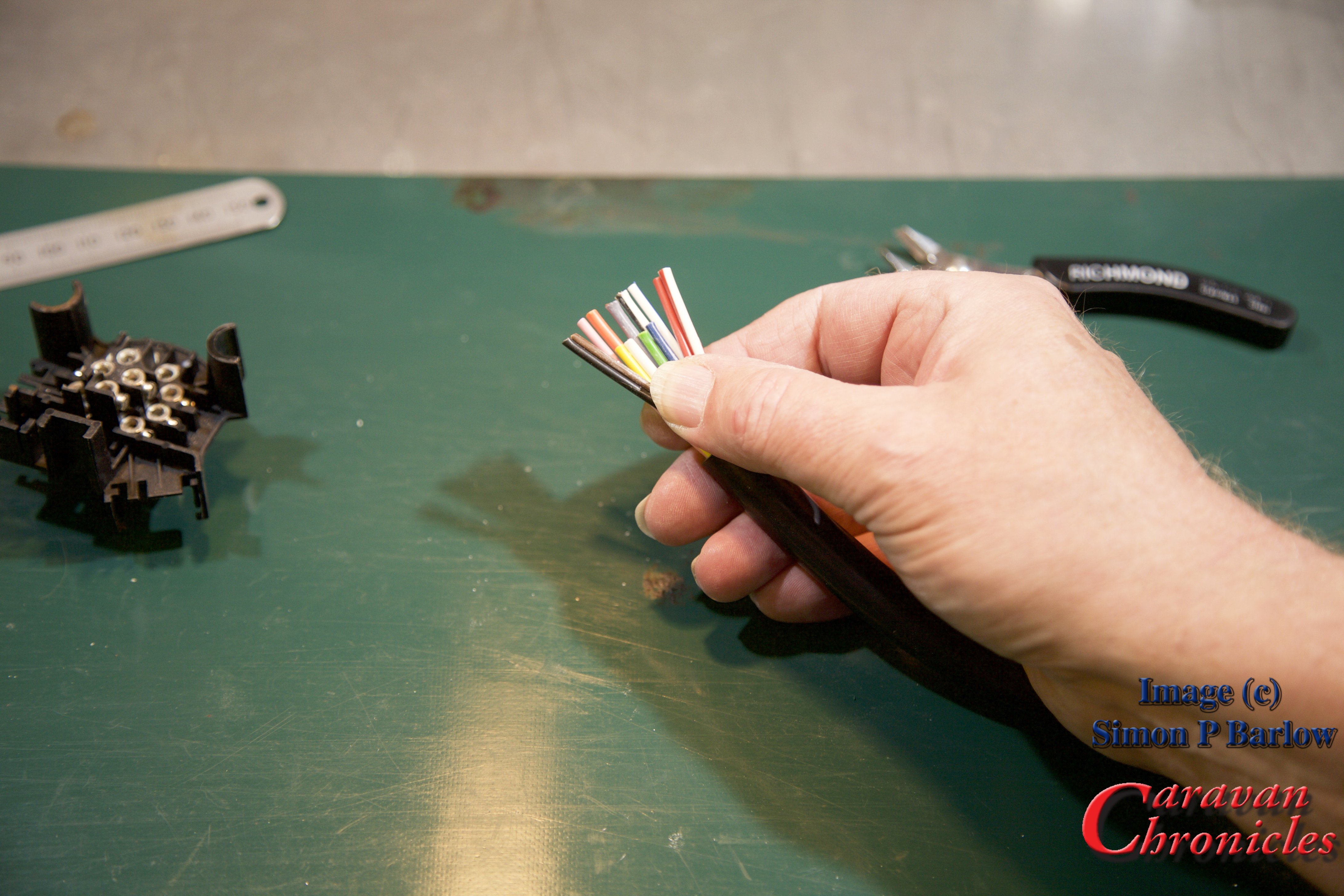
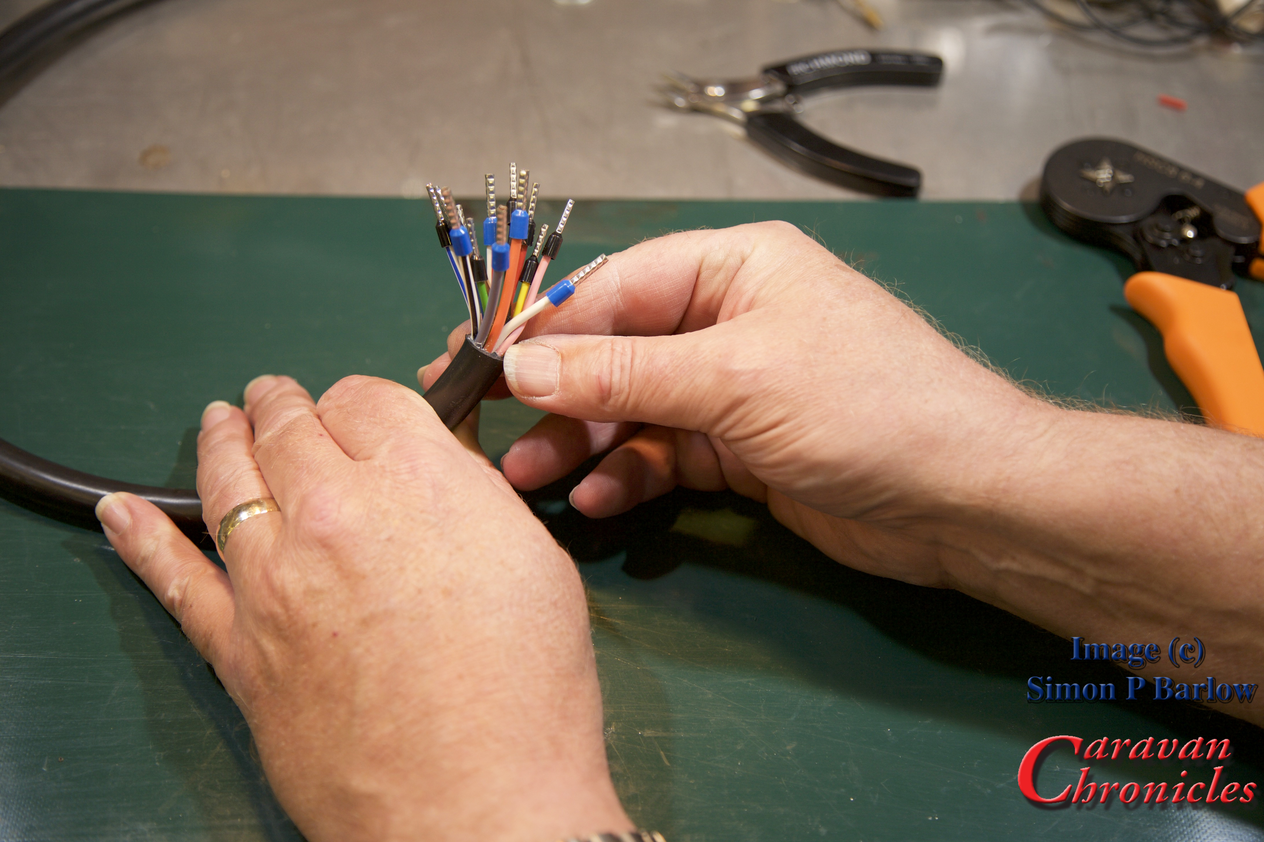
The next thing to check is have you got the right end of the cable? The cable manufacturers lay the individual conductors in a specific pattern so that when stripped, the pattern of colours is in the right order for the end you are terminating. If you have the incorrect end of the cable you will have to cross all the colours over each other to install them correctly in the plug (or socket) As you can see, this is the wrong end for a socket:

Ok, I’ve stripped the other end and you can see the colours are in the right ‘order’ for terminating a socket:

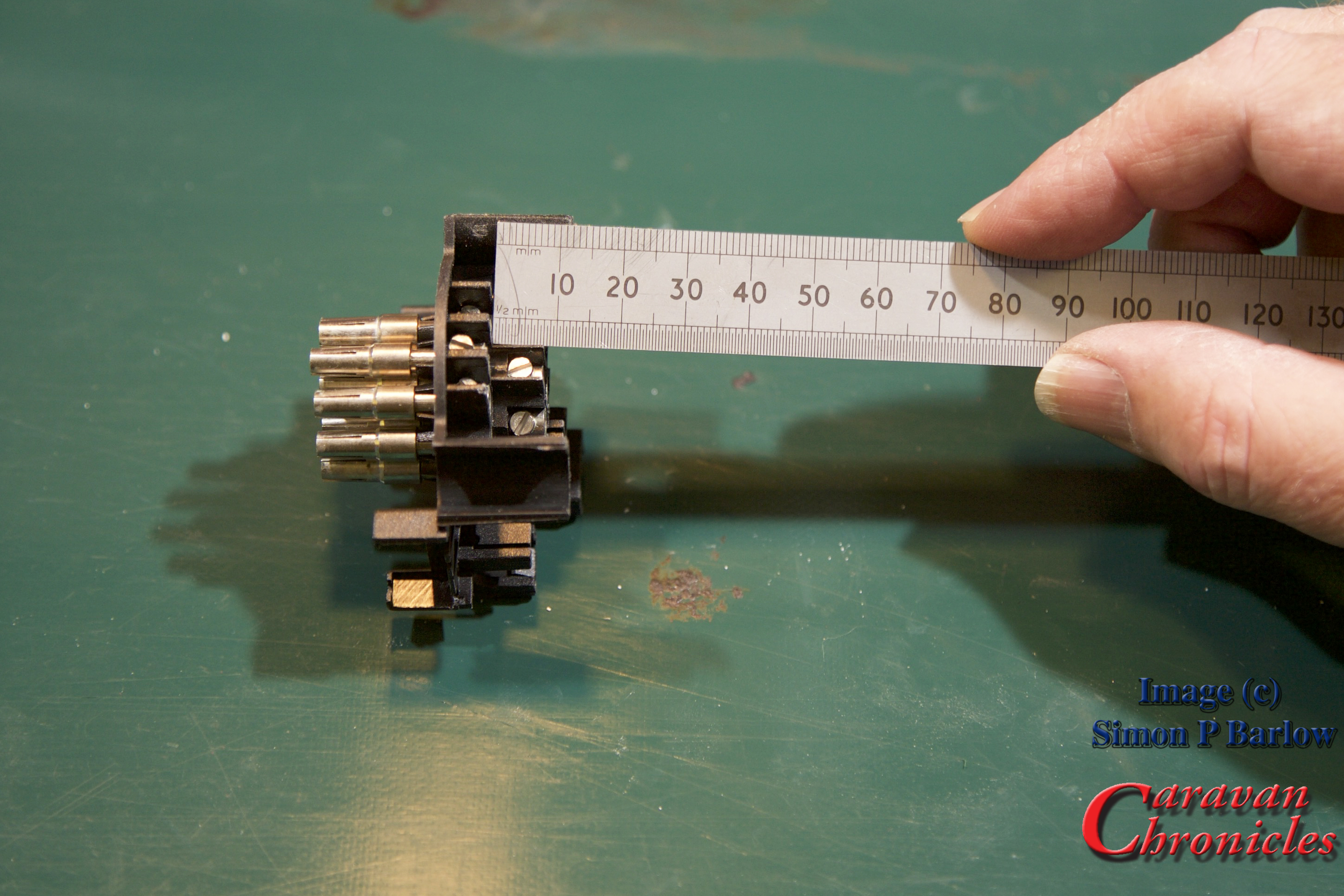
Next we need to measure the difference in termination length between the four centre line and the 9 outer pins… here it’s about 8 mm:
Measuring the back waterproofing cover I know the outer jacket needs to be a maximum of 45 mm from the 9 outer pins and the 4 inner pins need to be trimmed back to 37mm:
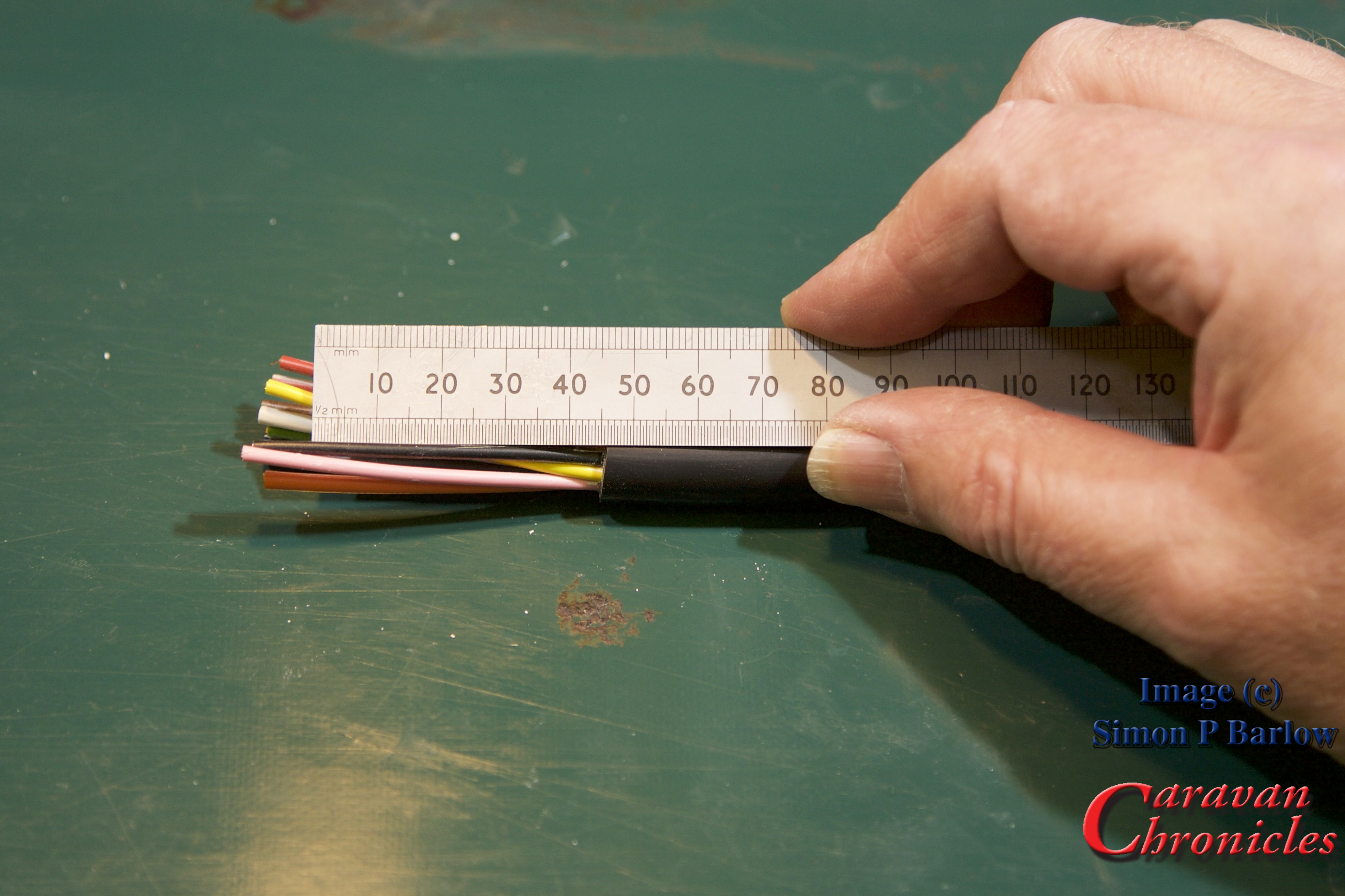
Now the cable is cut to the right length so there should be no short or long cables causing problems when assembling the socket:
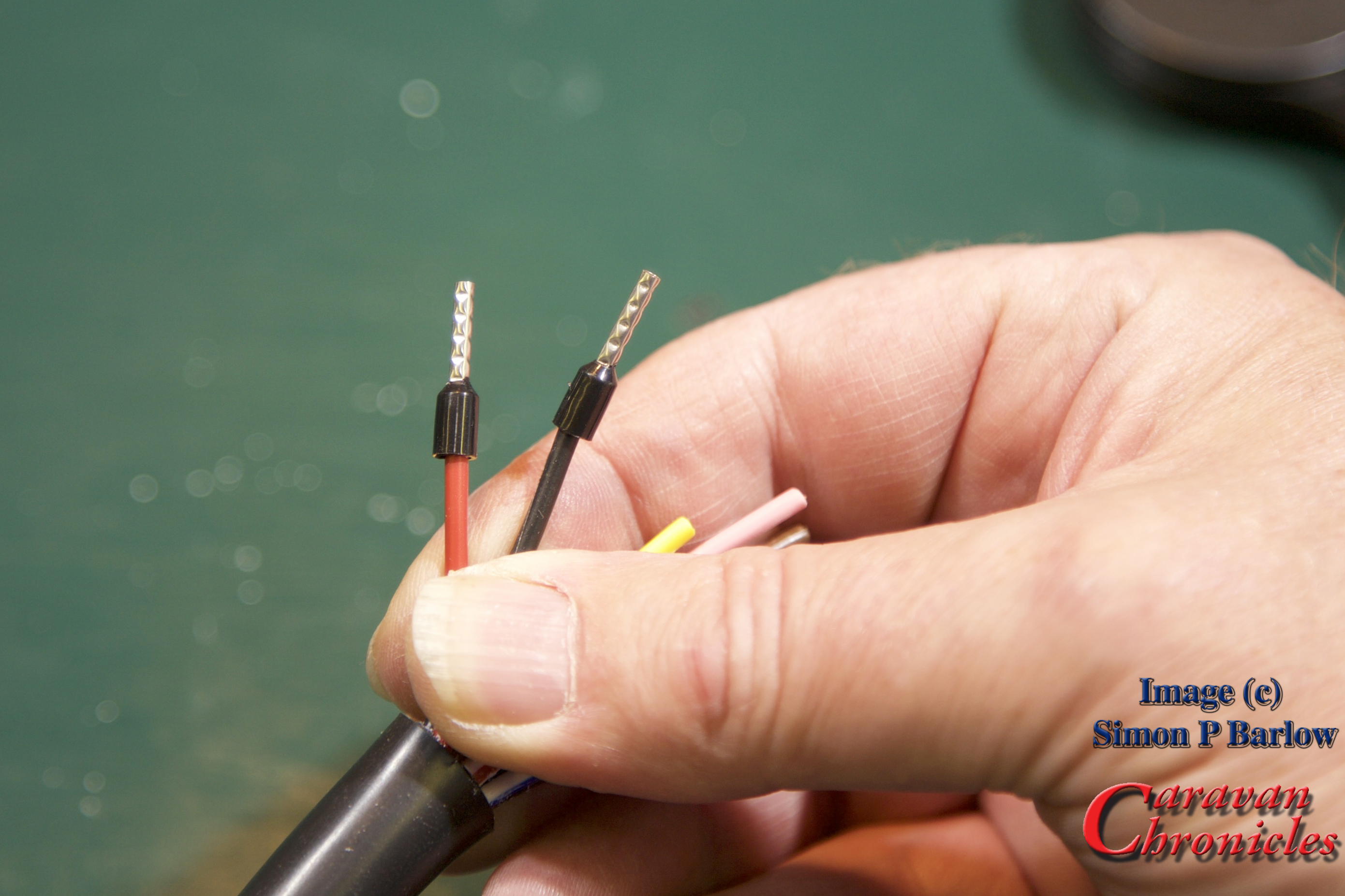
Strip back the individual cables so the exposed conductors are the same length as the ferrules:

Slide the correct diameter ferrule on to the exposed conductors:
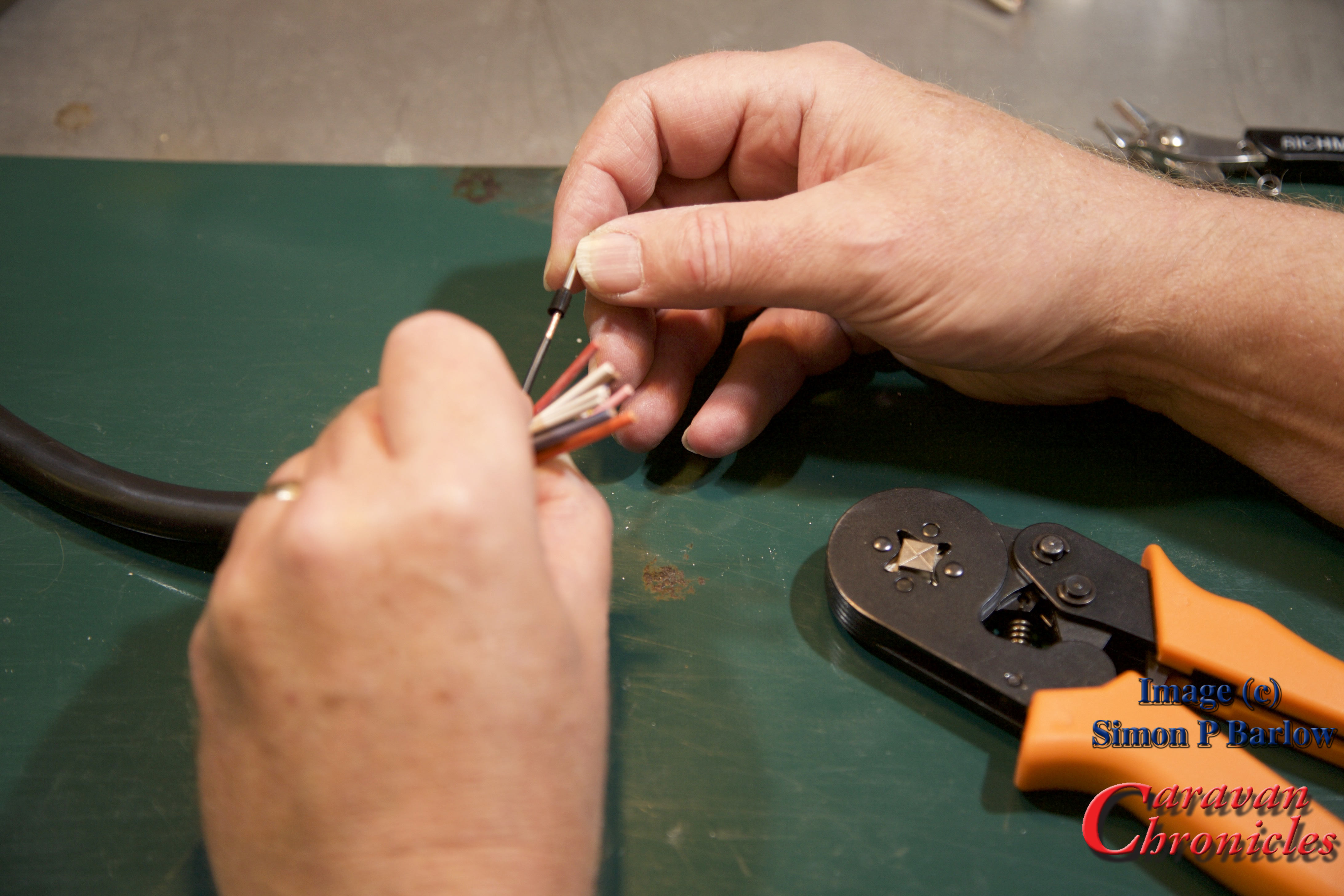
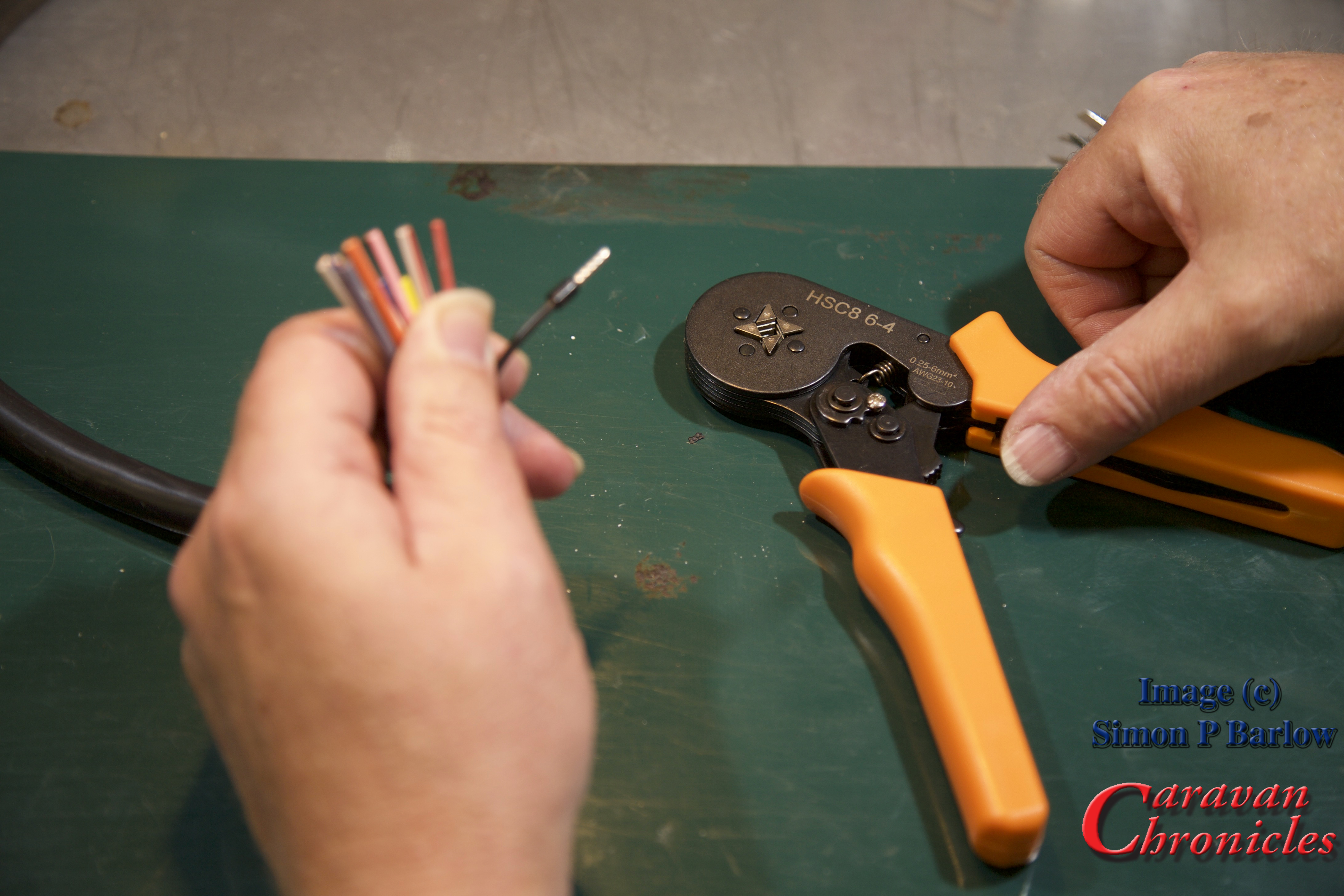
Crimp into place:
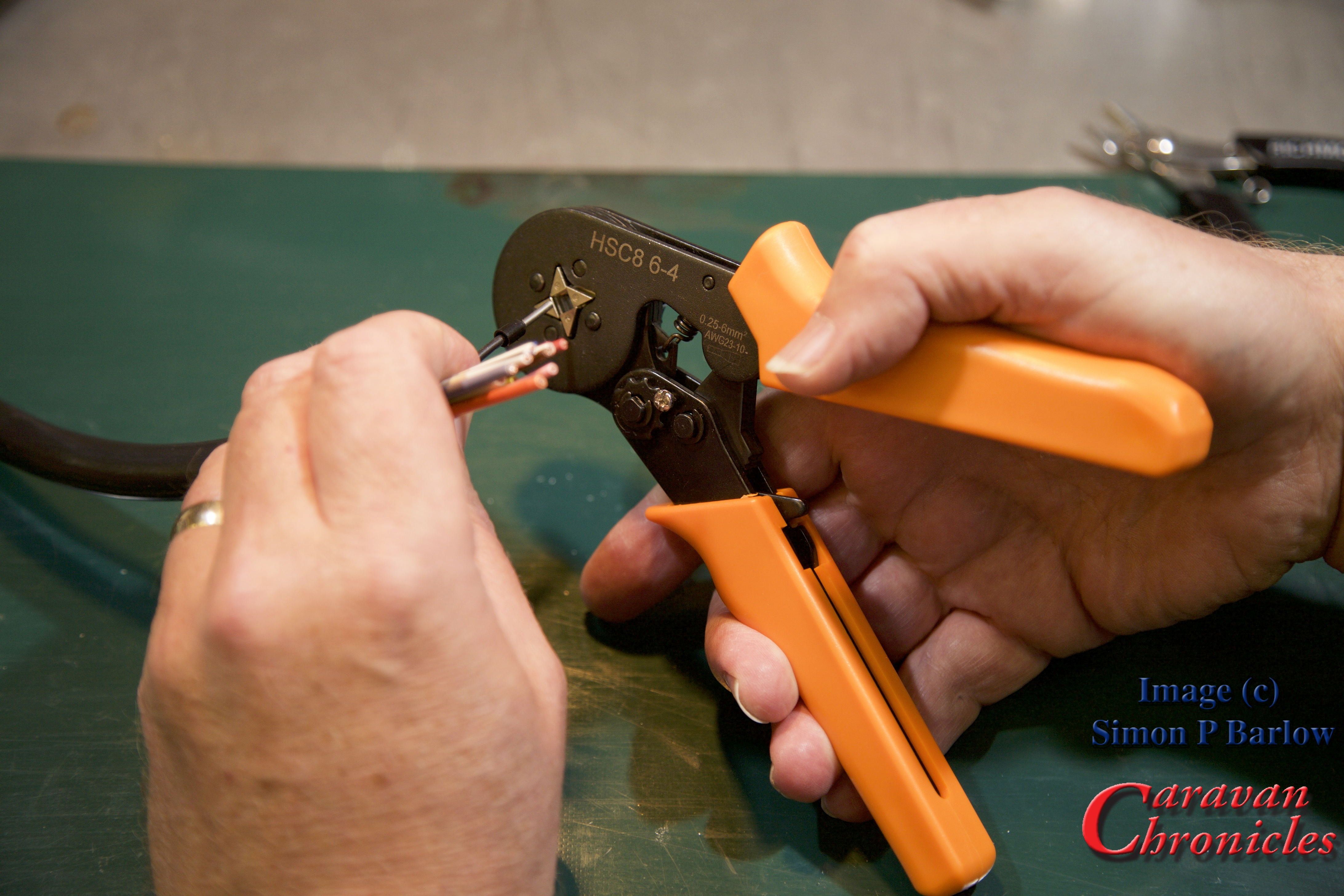
The crimp tool is set so that it will only apply the correct pressure to compress the exposed conductors the required amount. Squeeze the handles and the four jaws close on the ferrule and compress it, continue squeezing and once the jaws have attained the right pressure the ratchet mechanism in the handle releases.
If you look at the picture below you will also see that the crimp tool also presses several ridges into the tube, this is to increase the mechanical grip on the conductors and help stop the tube distorting under the pressure of the terminal screw tip:
Continue until you have all the cables completed:

One last check… look for stray strands and anything that doesn’t look as though its crimped correctly… give them the ‘tug’ test if in doubt.
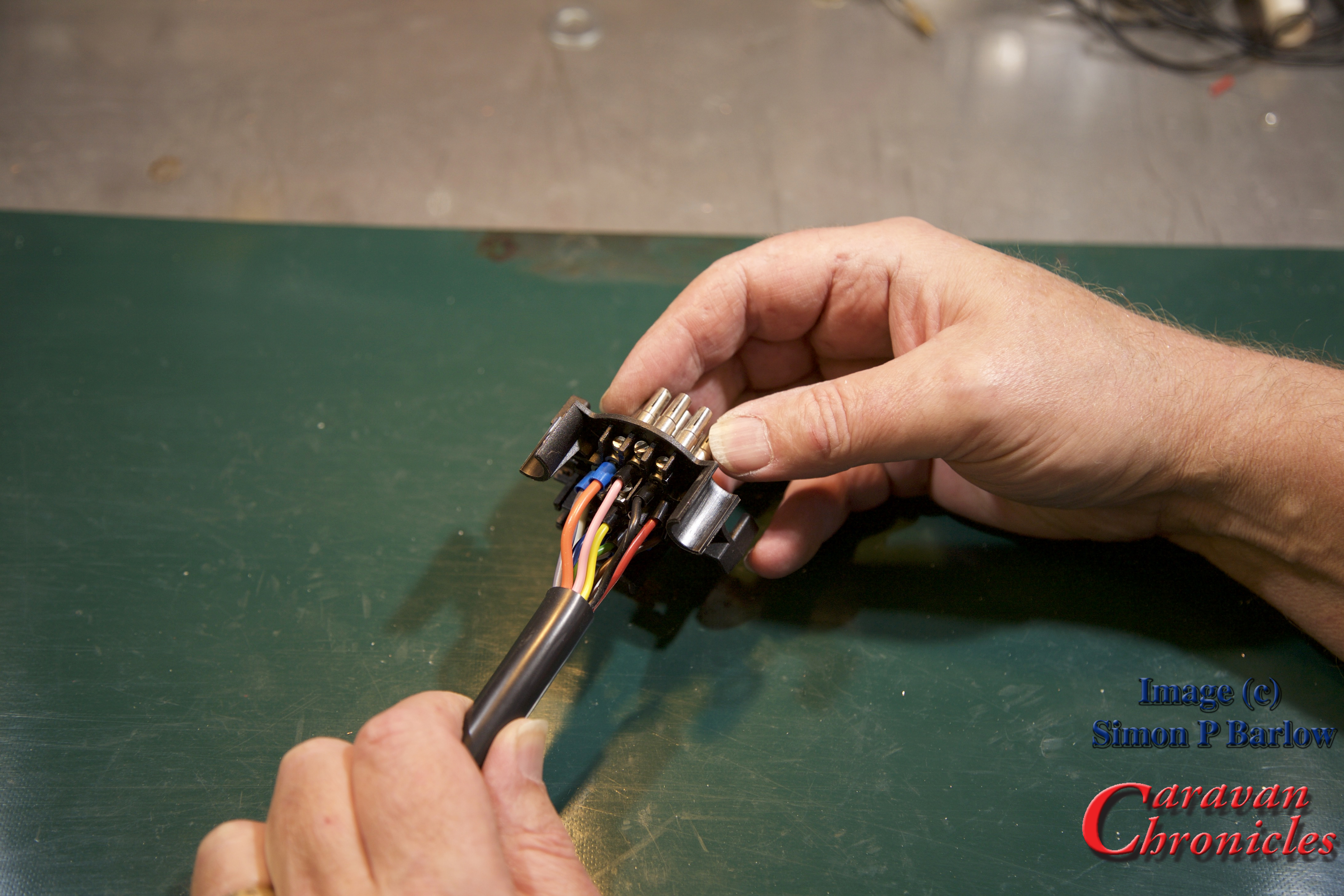
I always like to back off the screws so the ends are just visible in the holes:
The next thing you might need to do is correct the length of the ferrule. I have used standard length ferrules and as the holes in the socket terminals are not as deep, I had to trim off the excess. The ridges pressed into the ferrule body help gauge how much to trim off. In this case I only had to snip off to the first indent:

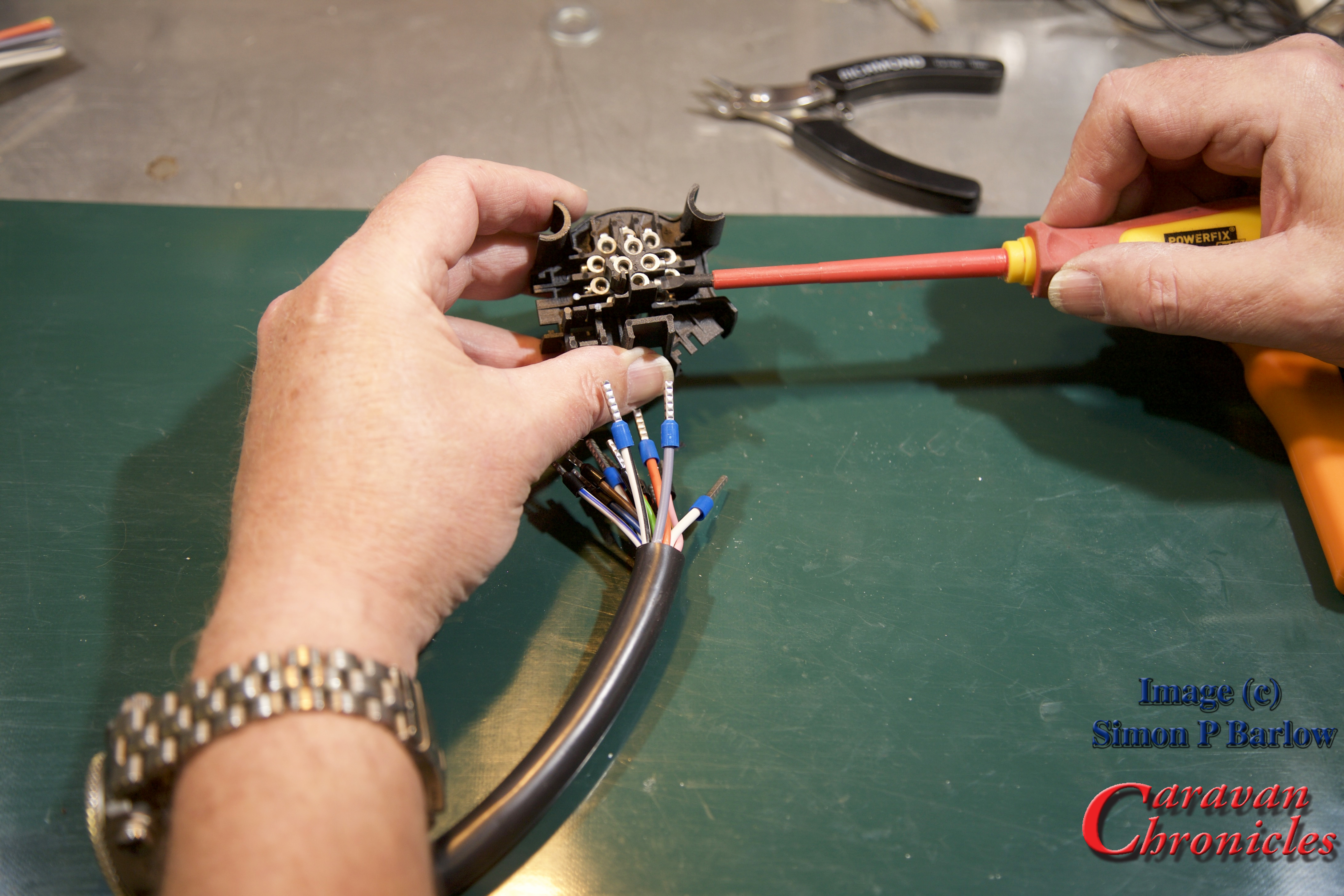
Once trimmed to length, it’s a simple matter of following the colour coding and inserting each cable and tightening the screw. I always start with the four pins in the middle:

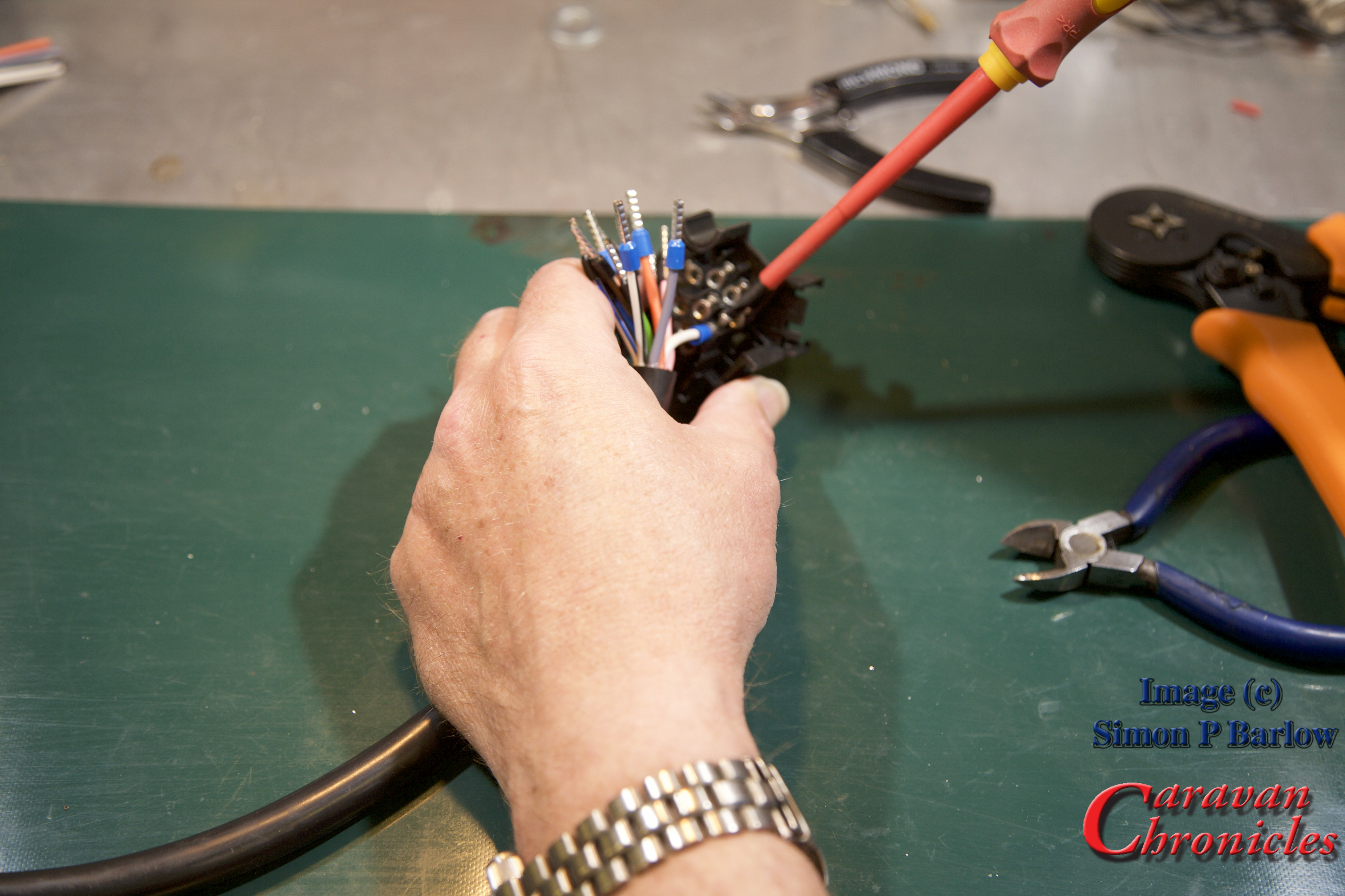
Once all the cables are terminated, have a good look to see if all the screws are tight, and of course check the colours are in the right place!
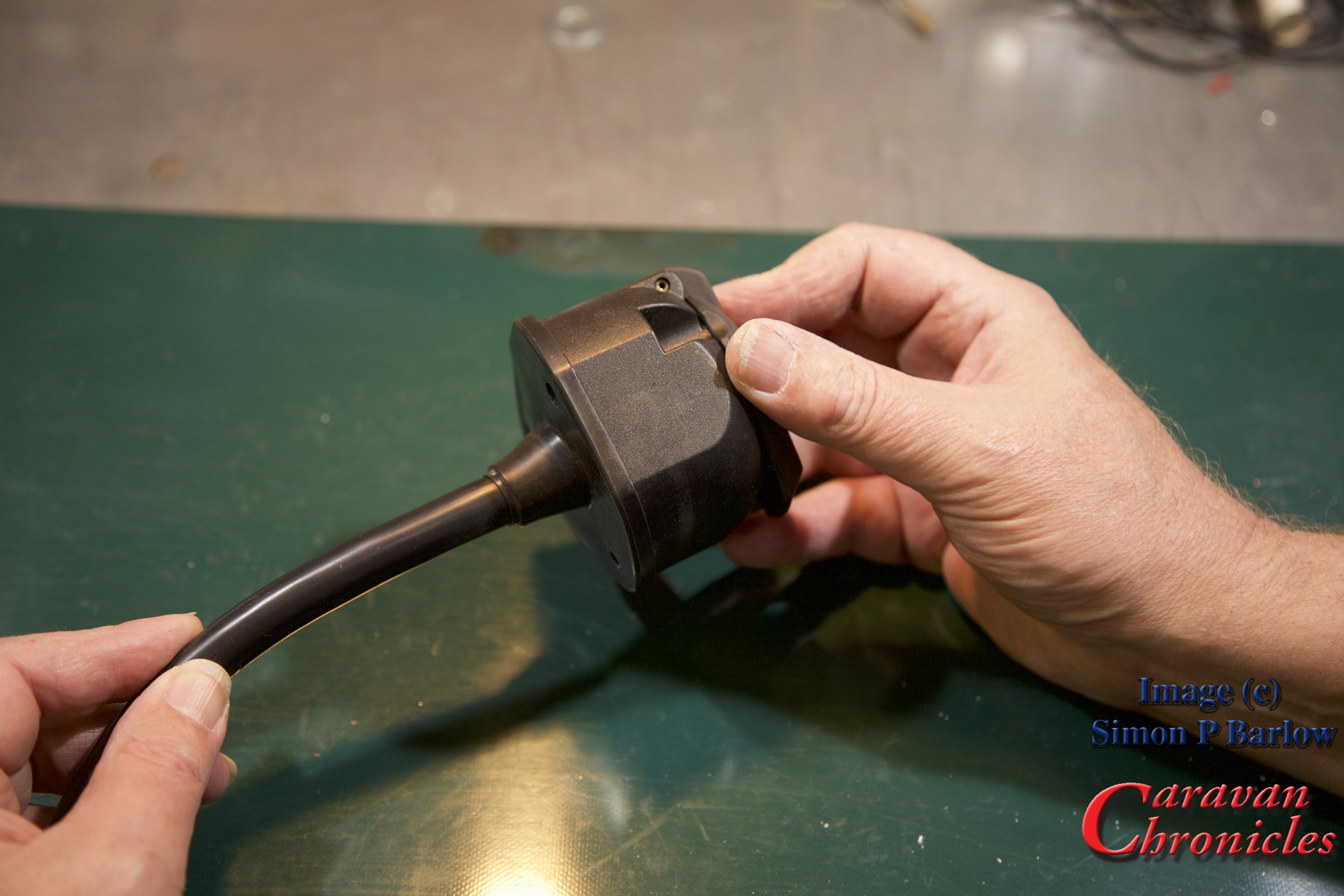
Because the cable was trimmed to the right length before we started there are no loops, so the cover can slide on neatly:

There we go, a finished socket all ready to mount onto the bracket:
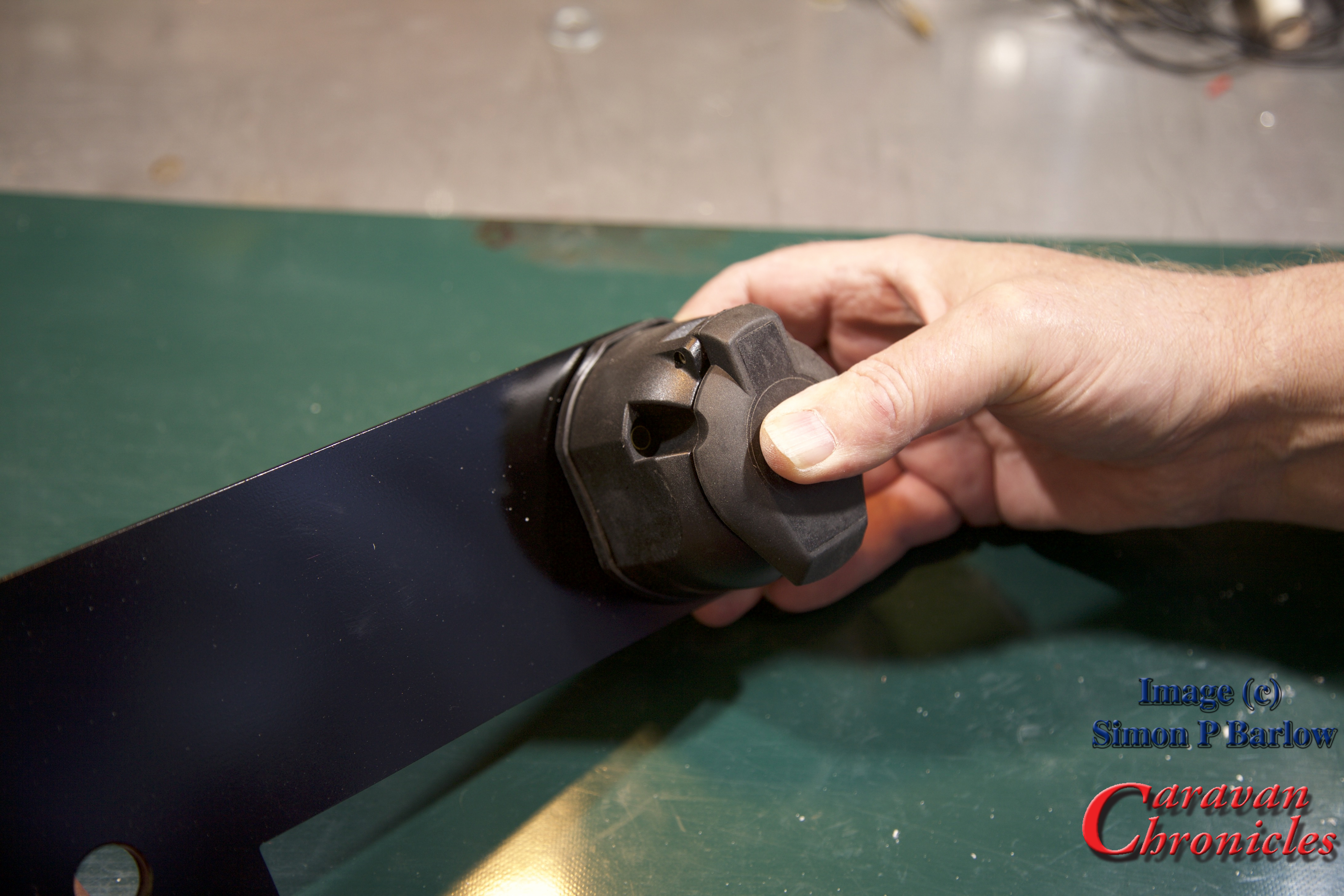
To terminate the socket from start to finish and while Sue (thanks `Sue) took all the photos took no more than 25 minutes. Ok it was on a bench and doing outside at the back of a vehicle will take a bit longer, but it’s not that difficult to get a professional result.
The ‘Compromise’
Right back at the start I said there was a compromise – soldering. It’s not difficult to do and achieve and end up with a professional result.
Practice makes perfect and its worth having a go on a scrap length of cable first.
Here’s a few of my tips for successful soldering:
Don’t apply too much heat to cause the insulation to melt (turning down the temperature of the soldering iron or reducing the contact time between the soldering iron and cable helps)
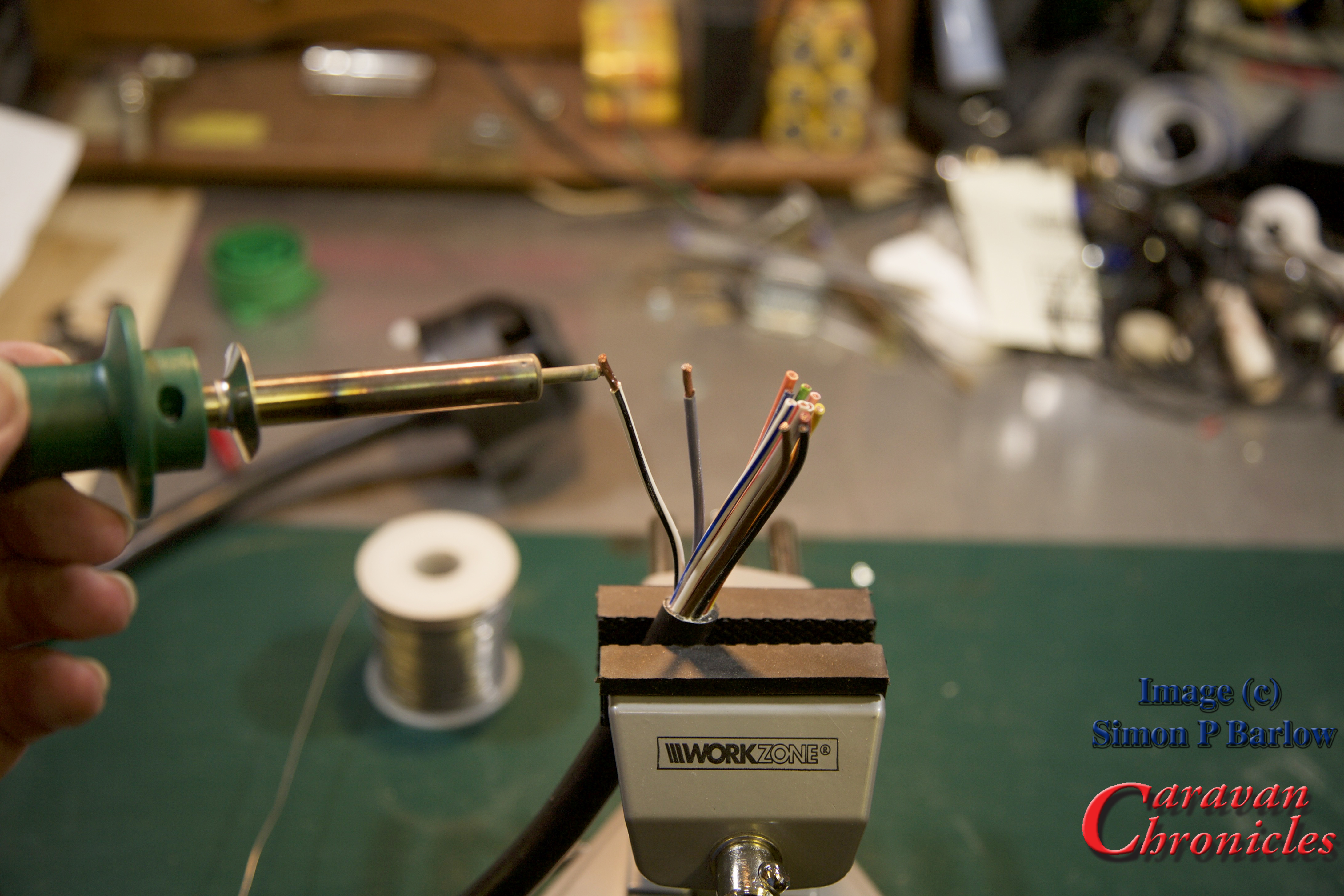
Don’t try to melt solder onto the tip of the iron and run it in to the cable you will burn off the flux too fast… instead touch the solder onto the hot strands of the conductor. Capillary action will pull solder into the strand bundle.
Don’t allow too much solder to be drawn in. You are looking for just enough to still be able to make the outlines of the strands of cable, not a big ‘blob’ of solder on the end.

The solder should look shiny not dull. If it’s dull, the solder cooled too soon as the conductors were not hot enough, this is commonly known as a ‘dry joint’ the solder sits on the surface of the copper.

Avoid breathing in the fumes given off from the flux and the solder. Solder is an alloy of tin and lead… and the flux is pretty nasty too. ( I have an old computer cooling fan that I use to blow the fumes away if I’m doing a lot of soldering).
If you have made the soldered cables too long, you can always trim them back to the correct length. Soldering all the conductors in a caravan cable like this usually takes me no more than five minutes from start to finish.
A few practice runs will soon get you producing good results.
Finally to finish off, I usually give the finished connections a spray of ‘liquid plastic’. It comes in an aerosol can and when sprayed on form a thin plastic coating over everything. You can usually find it in motorbike and automotive shops for waterproofing electrics and HT leads.
It easy to get a good professional result, and I still can’t understand why some tow bar fitting companies don’t either crimp or solder their connections. They usually do when it comes to connecting the other end of the cable to the vehicle. The cynic in me wonders if they are hoping for repeat custom when sockets or plugs start to have problems in the future.
Caravan Chronicles Shopping...
I have been asked where you can purchase some of the products featured above. Here are the links to the products in the Amazon store. If you click on the links and purchase the items, a few pennies will go to helping the cost of running CaravanChronicles.com
Crimp Tool : Hsc8 6-4 Self-adjustable Ratcheting Square Ferrule Crimping Plier for 0.25-6.0mm² Wire Terminal

Wire Ferrules : 750x AWG18 AWG16 Wire Crimp Insulated Ferrule Pin Cord End Terminal

Soldering Iron : 50w Variable Temperature Adjustable Controlled Solder Station Iron Gun Soldering Kit Set
Solder : Solder with Cored Flux 100g 60/40 Tin Lead Resin 0.7mm
13 Pin Milenco Socket : MILENCO 13 Pin Socket Black Caravan / Motorhome / Trailer

13 Pin Milenco Plug : Milenco 13 Pin Plug
13 Core Cable (8 x 1.5mm + 5 x 2.5mm) ISO Approved : 13 Core Caravan Cable Sold per metre

I’ll have a look at it as a project.
Nice blog – thanks
I’ve heard that soldering is especially a no-no for high current situations. If a few strands of the wire get broken (or if the plug gets hot from a dirty pin) the wire at that point can get very hot, melt the solder and loosen the joint making the connection worse and hotter still.
Hi Tom
Glad you like the blog, thanks.
Soldering cables into terminals can be a bit of a issue. To start with the flux that is used in most solder is acidic so that as it heats up is causes a chemical reaction which helps clean the copper, but over a longer period, unless the solder is heated high enough and long enough to drive off the flux so none is left (but not too much), it can cause oxidisation of the copper and create a problem later on. Some people advocate “tinning’ the end of the cable, then crimping the terminal on to the tinned end. Well the terminal is designed to crush the cable to a known point, tinning the cable makes this almost impossible. In addition, the tinned end of the cable will not be smooth and the surface area of contact between tinned cable and terminal sleeve could be reduced effecting the overall performance of the joint. There is also the problems of hardening the copper through heating and having a structural weak point at the junction of tinned copper and untied copper. Most of this also occurs when crimped terminals are ‘back filled’ with solder too.
The whole subject of cable termination and it’s problems could fill a blog of its own and the more you delve into it, the more you realise there is no perfect way to terminate a cable. I’m not an expert by any means in cable termination, but I tend to fall back on the standards and practices that I have to use for termination of cables for aviation use as the guys that produce terminals and tooling for this have done lots of research on the subject. It just needs translation into the real world of being practical for anyone to achieve.
I’ve been asked a few times (since I wrote the post on the correct way to connect two batteries in parallel) the best way to make battery cables. I’m just starting to get to gather all the bits I’ll need to do a write up on this.
Cheers
Simon
Sorry, forgot to put my name to the above post; Colin (snowy)
Hi Simon,
Firstly, all the best to you and Sue for 2016. As usual your information with regard to the subject of Cable Termination is spot on, you can often see examples of your points upon Mains Plugs that have been factory fitted to household electrical appliances. As for my self, I solder the ends and then while the solder is still hot, stretch the cable strands’ outer insulator so far over the solder part as to strengthen the week part where the solder ends if you know what I mean. This is not optimum, but is quite acceptable in my opinion.
I appreciate the tutorial, I feel reassured about the way I solder wires.
Hi Simon, good to see you back blogging after so long away.
Excellent article, and goes a long way to explain some of my electrical problems over the years. I think I need to invest in wire strippers and crimpers and stop using the kitchen scissors and a rusty old stanley knife!
John
PS – When a ferrule is on a boot-lace it is actually an aglet.
PPS – Couple of typos – striped should be stripped, trip should be strip (twice), lady should be lay, and crews should be screws (sorry!).
PPPS – Where was your main home-page picture taken, as it looks a nice site?
Hi John, Happy New Year!
Thanks for spotting the typos… my editor-in-chief (Sue) wasn’t looking over my shoulder!
The main picture was taken at Lady Margarets, Chirk in December 2012. It was a very windy week – gales most of the time so there were only 4 caravans on site. We were doing the Christmas markets at Wrexham, Chirk Castle and Erddig. The site is a great place to base yourself from, lots to see in the local area.
S
When I worked in the electrical industry our big boss would not let us solder or crimp wire ends. He said that if a screw came loose the stranded wire would expand and follow the screw.
Hi David
Hmm… I can’t see the logic in that, if the screw becomes loose, the copper strands are already deformed by the pressure of the screw on initial tightening and copper has little or no ‘spring’ in it as a material. With strands under a screw, its more likely to come loose as the strands can move with vibration releasing the pressure on the terminal screw. With something solid under the screw (solder or a ferrule), you can increase the torque of the screw to reduce the chance of vibration loosening it.
Maybe I’m missing something?
Simon