
Following the article Caravan Road Lights – Basic Fault Finding this article helps you to go through a simple series of steps to trace a fault in your caravan or trailer’s road lights.
I’ve written this simply as I can in easy basic steps so that hopefully anyone with a little understanding will be able to ‘help themselves” as much as they can before having to ask for assistance.
Tracing a fault is all about simple logical steps and proving each part of the circuit rather than trying to test the whole thing in one go.
FAULT: Right hand indicator doesn’t work.
So we have gone through the basic fault-finding steps. We have checked the 13 Pin socket on the tow vehicle and the RH indicator works. We have checked the indicator bulb and that tested OK with the multimeter. We have checked the internal fuses (if any) for the road light circuits and they are all OK.
We tested the 13 pin socket on the tow vehicle (13 Pin Socket – Basic Fault Finding) and found everything to be working correctly including the connection for the Right Hand Indicator, but when the caravan or trailer was connected to the tow vehicle, the right hand indicator wasn’t functioning.
Lets have a closer look at the circuit for the indicator wiring in the caravan drawn out:
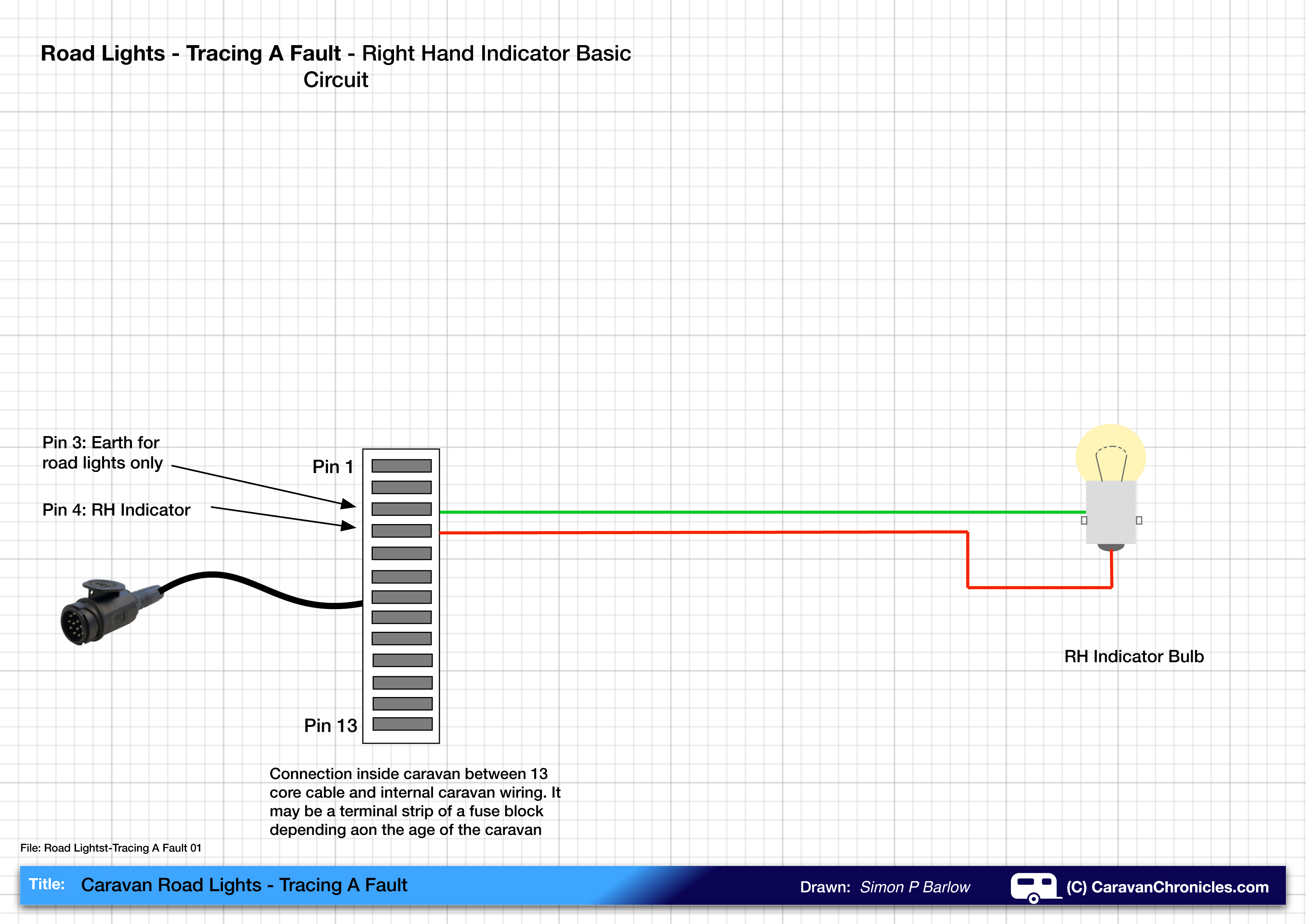
Circuit Description: The 13 pin plug has a multi core cable that routes along the ‘A’ frame and will enter the caravan, usually through the floor. Inside the caravan it will terminate in either a connection strip or fuse box. From the connection strip or fuse box, the circuit will continue along the caravan’s internal wiring to the rear of the caravan where it will be routed to the light cluster.
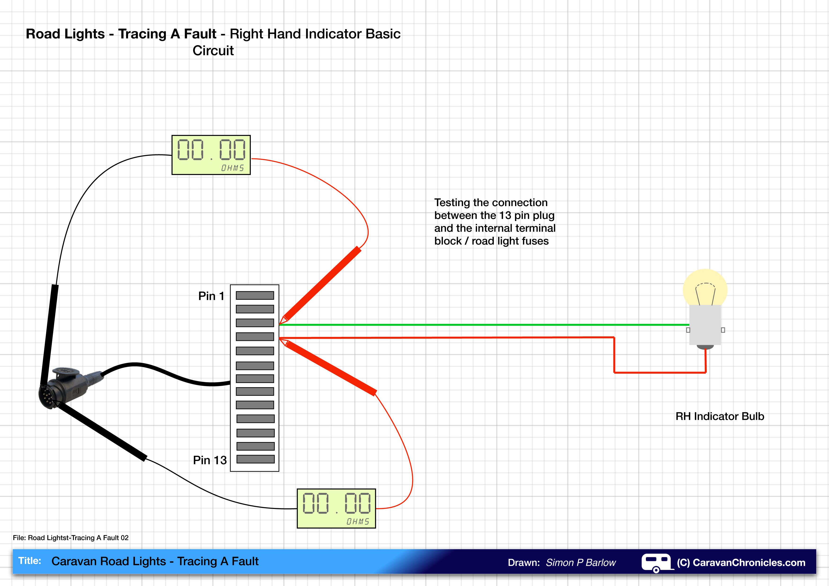
Step One – Test the continuity between the 13 pin plug and the internal connection block or fuse box.
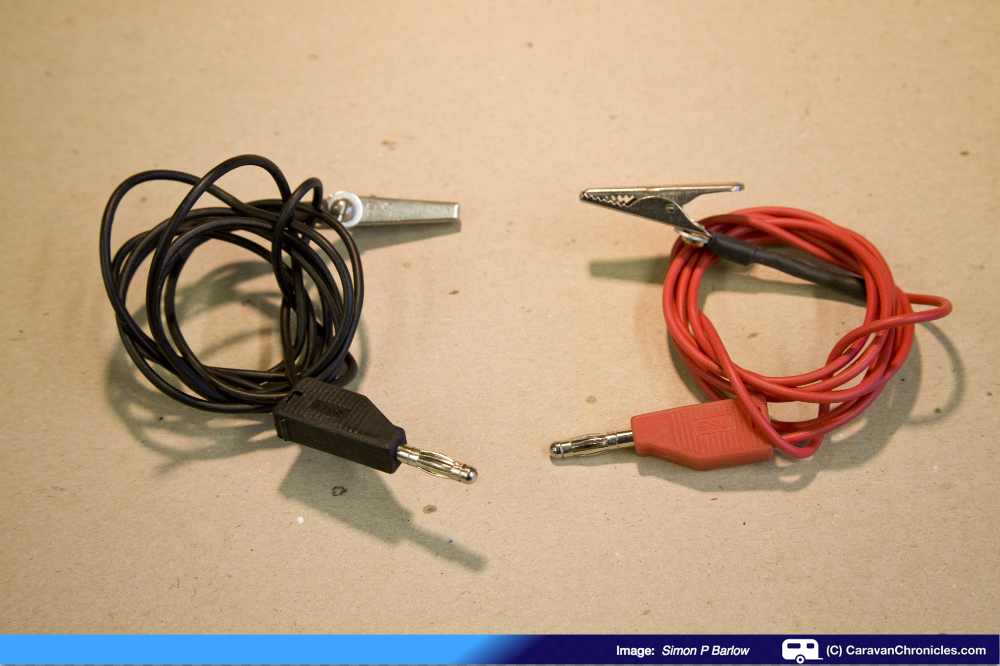
To do this you really need an assistant and a length of wire that can extend one of the test leads on your multimeter. One of the later tests will require a lead that can reach from the front to the back of the caravan. I’ve put some details at the bottom of the article.
Before taking any resistance readings on your multimeter, remember to set the multimeter to the correct range, and touch the tips of the test leads together to ensure you get a reading of 00.00 Ohms.
Note about resistance readings: In an ideal circuit, you should always get a reading of 00.00 Ohms. However, it’s never ideal and you will get readings that are slightly above. In a 12 volt circuit any reading between 00.00 and 00.50 is acceptable. If it is higher than 00.50 then we usually need to find out why. The most likely cause is a ‘high resistance’ connection and its usually down to some surface corrosion on a connection or a badly made (crimped or soldered) joint.
Once you have located the terminal block or fuse box inside the caravan and identified the connections for Pin 3 (Earth) and Pin 4 (RH Indicator +ve ). Connect one test lead to the appropriate pin (3) on the 13 pin plug and the other to the corresponding terminal or fuse in the terminal block or fuse box. You might have to pass the test lead to an assistant through one of the windows of the caravan to do this. The reading should be 00.00
Next repeat the test for Pin 4 and the corresponding connection on the terminal strip or fuse box. Again the reading should be 00.00
At this point, if one of the readings is not 00.00 it displays ‘OC’ (Open Circuit) or ‘OL” (Open Line) on you meter or a reading above 00.00 then you need to stop and investigate. The fault could be caused by a break in the circuit or by a high resistance. The most frequent problem is a faulty connection within the 13 pin plug or terminal strip/fuse box.
If everything up to this point checks out OK, then we move on and test the next section of the circuit.
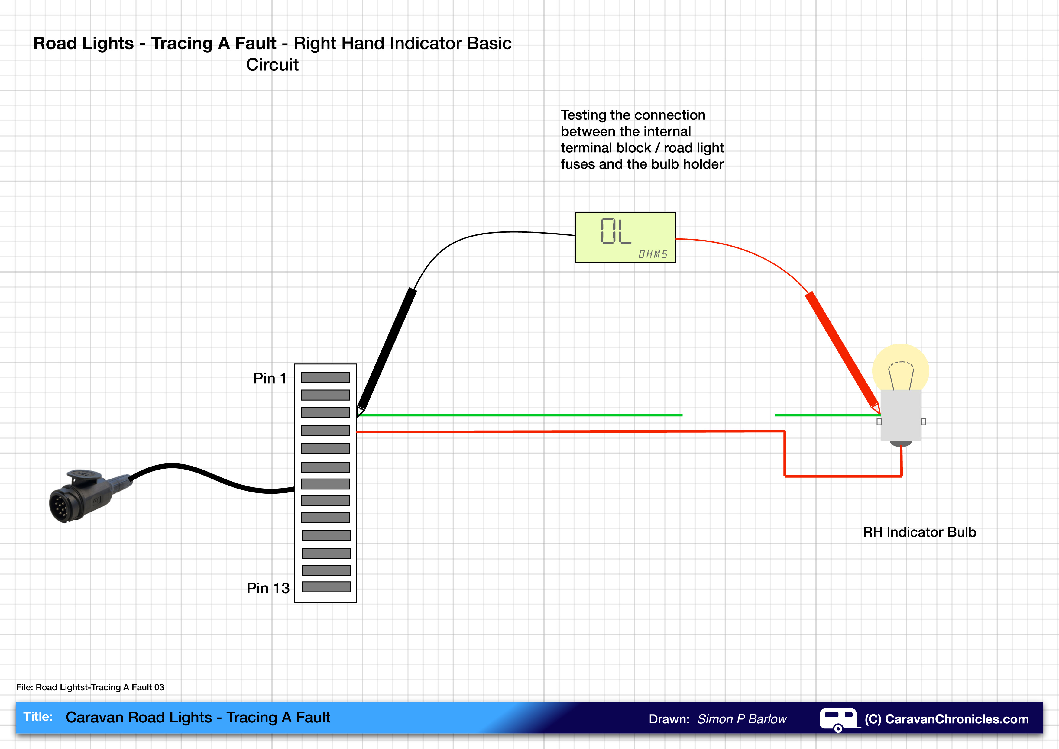
Step Two – The second test involves testing the continuity between the terminal block or fuse box to the actual bulb holder at the rear of the caravan or trailer. You will need an extension for your test lead that is long enough to reach from the terminal block or fuse box to the rear of the caravan or trailer.
We first check the indicator +ve wire. Connect one end of your extended test lead to the correct terminal on the terminal block or fuse box and take your extended test lead with meter attached to the rear of the caravan. Remove the lens cover and bulb if you haven’t already done so and now check the centre contact of the bulb holder. If the circuit is OK you should get a reading of 00.00. If the reading is above this, then you have a high resistance connection in the cable. If it read ‘OC’ or ‘OL” then you don’t have a circuit. You will need to trace the wiring through the caravan to see if there is a break in the cable or a faulty connection somewhere. Assuming the circuit is OK, we will carry on.

We now need to check the ‘Earth’ return path of the circuit. Move your connection from the +ve terminal in the connection block or fuse box over to the ‘Earth’ terminal. Now at the rear of the caravan you need to test the earth connection on the bulb holder. This is usually the metal sleeve that the bulb locates into. You might have to ‘scratch’ the tip of the test lead probe slightly on the surface to get a reading. If this is the case, use a small piece of ‘scotchbright’ or fine emery paper to remove any surface corrosion. You should get a reading of 00.00.
In our test, we have a reading of “OL” (or “OC” – Open Line or Open Circuit)
This means we have a break in the earth circuit somewhere. Yet we assumed that the earth was OK as when the caravan was plugged into the tow vehicle all the other lights worked.
Coffee Time…
We need to apply some logical thinking. We know the +ve side of the circuit test’s OK. We know the ‘Earth’ tests OK to the Terminal block (or fuse box). We know that the earth works on the other lights because they work when the tow vehicle is plugged in.
This means there must be an “Earth’ cable from the indicator bulb holder to an Earth point or earth on another light…. and this must be open-circuit. How can we check this?
Remove the lens cover from another light – (lets use the rear fog light) we know works. The multimeter test lead is still connected to the ‘Earth’ point on the Terminal Block (Fuse Box) so simply put the other test lead probe on to the bulb holder of the fog light. We get a reading of 00.00 We have now proved the ‘Earth’ to the other bulb holder. If we look at the drawing below, it must be similar to this…..
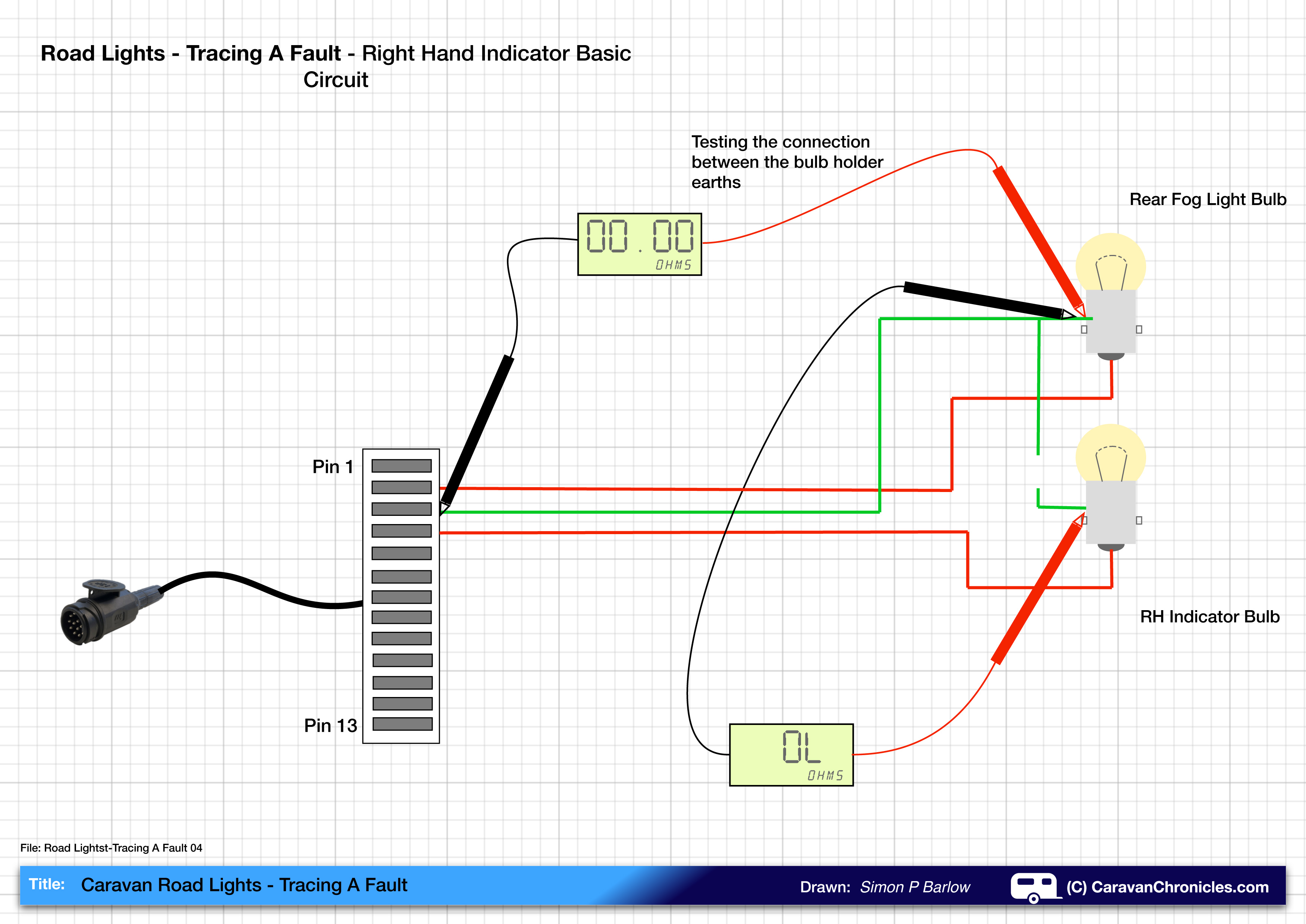
In this case, the earth from the indicator connects to the earth in the rear fog light, it could however connect to an earth point in one of the other light units.
We have now confirmed that the ‘Earth’ to the other light is working, so it’s now a simple matter of tracing the earth from the bulb holder of the right hand indicator to where it connects to the earth point for the other lights.It is always worth checking connections first, it is more likely it is a connection than a break in the actual cable run.
Testing of other lights is accomplished in much the same manner, although there are a few short cuts. Because the two brake lights are on the same circuit, after checking the fuse and the bulbs are working, but only one brake light operates, check the side lights. (Remember, the brake light bulbs are usually two filament bulbs, one is the side light and the other is the brake light) If the side light does not work either, then the earth connection to the bulb holder is suspect and a simple test to check the resistance between the non working bulb holder to a working bulb holder will confirm if the earth is the problem.
If both side lights work with only one brake light, check the connection between the +ve bulb connection on one brake light to the +ve connection on the other brake light. It should read 00.00. If it is higher or “OC” / “OL” then there is a fault with the +ve feed to the bulb holder.
I said at the start “Tracing a fault is all about simple logical steps and proving each part of the circuit rather than trying to test the whole thing in one go.” It is really quite simple and the easiest method is to draw the circuit out you want to test – copying it from your caravan or trailer handbook. Once drawn, just simply start at one end and prove each cable line drawn on your paper as we have done above. It won’t be long before you can mentally visualise the circuit and fault-find like a professional.
Why not just check the voltage?
I’m sometimes asked why don’t I just plug the caravan in to the vehicle, turn on the lights and use my multimeter to check the voltage at each point? A couple of reasons. 12 volts is not a big voltage, but the energy that is stored in a battery is huge, short out the wrong bits and there is a bit of a flash and a blown fuse somewhere to add to your original problem. Always err on the side of caution and safety. Try and do all of your testing with the caravan or trailer disconnected. The second reason is high resistance connections. Sometimes, you can measure a voltage at a bulb holder and you see 12.8 volts and think it must be working, but you install a bulb and it doesn’t work. The reason is there is a high resistance connection somewhere and testing with a voltmeter doesn’t show this. There is enough current (milliamps) to make your meter display a voltage, but not enough to light a bulb. By testing using the resistance setting, you are also checking to see if there are any high resistance connections.
I hope you have found this and some of the other guides useful.
As usual, I have added the drawings in PDF format at the bottom of the page so you can add them to your iPad, Tablet or eReader…
S
Extending Your Multimeter’s Test Leads…
More kit for your tool box!
In order to extend the ‘reach’ of my multimeter’s test leads, I have made up a few additional leads. A word of caution, you must always be aware of what your leads are connected to. Accidental shorting of leads or having the multimeter set wrongly is all too easy and can be dangerous. When you have finished taking a reading, if you are going to take a break, always disconnect your test leads and turn your multimeter off.
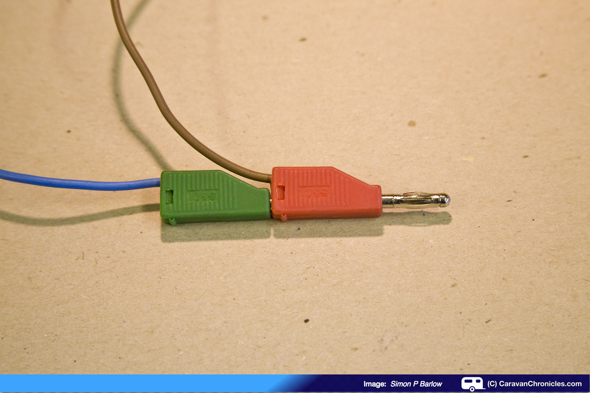
The ones below can be used by directly plug in into the multimeter and allow me to use the crocodile clips to attach directly to cables or terminals leaving my hands free. Most multimeters use 4mm post connections, the plugs are known as ‘4mm banana plugs”. I have made up leads in 1.5, 3 and 10 metre lengths…….
Using one of the leads to extend the negative test lead by 1.5 metres. The crocodile clip is connected to the shrouded 4mm plug of the metres normal test lead. It is important that you ‘prove’ your test lead by connecting the tips of the test lead while set on resistance range. IN this case the reading is 00.00 so I know the lead and connection is fine to use.

4mm banana plugs also allow you to stack them if required…..
… and you can buy crocodile clips that just push on to the ends of the plugs…..

The plugs and crocodile clips are available from Maplins and other good electronic’s shops.
Road Lights – Tracing A Fault 01
Road Lights – Tracing A Fault 02
Road Lights – Tracing A Fault 03
Road Lights – Tracing A Fault 04
Understanding Watts, Amps, Volts and Ohms – A very basic introduction to some simple maths that allow you to work out power, current and resistance.
Cable Termination 101 – A look at how to achieve a professional quality cable termination.
Copyright © 2011 – 2019 Simon P Barlow – All rights reserved


Hi my right hand indicator is not working on my caravan when plugged into my transit .
But works when I plugged into my mates car .
This tells me there is a problem on my transit
Where do I start
Have checked the wiring to pins and they all seem ok can anyone help
Hi Jason
Try reading https://caravanchronicles.com/guides/13-pin-socket-basic-fault-finding/ on how to check your tow vehicle’s 13 pin socket.
Hi Simon
Thanks for getting back to me, the series circuit sounds good but I wonder how the lights would work if plugging in a normal 21 watt lamp ?
For the parallel circuit we could trigger the beep when no trailer is connected ? but would get over the series / 21 Watt issue.
Need to brush up on ohms law and check it all out.
Many thanks again, is it ok to pass on my sums to you to see if I am on the right track, a long time ago that I looked at ohms law.
Graeme
Hi Simon
Just been looking around your web pages, very good source of info.
My problem relates to LED indicators that are on our new Bailey Unicorn, every thing in terms of lights functions well apart from the beeper in the car when the indicators are used.
Our other caravans had normal lamps 21 watts for the indicators, I am thinking that the current draw for the LED’s falls way short of triggering the voltage sensing indicator relay to trigger the beeper ? ifrunning the hazard indicators the beeper works.
Do you know if the indicator relay / beeper has a sensitivity adjustment ?
Have you come across this before ? is my understanding correct ?
I was wondering about placing a resistor in parallel with the indicator LED’s in order to create some more load, but the question of warranty for the caravan will be an issue.
Hopefully this makes sense
Graeme Puttt
Hi Graham
The issue of LED lights on caravans is causing some issues.
I don’t know of any indicator relay that is adjustable for sensitivity, but you are spot on about the current being to low for the indicator relay to pick up.
My first thoughts would be to do exactly what you suggest and put a resistor in to increase the current draw. There is a couple of ways you could do this, either in parallel or in series. I think I’d opt to put a 1 or 2 Ohm resistor in series (LED’s have very low forward resistance). The voltage drop across it won’t be enough to stop the LED indicators from working but might be enough to fool the indicator flasher into thinking it was a filament bulb.
Putting a resistor in parallel would do the same, but it’s a bit more of a balancing act to get the value right – low enough to trigger the relay sensing correctly but not to overload the circuit.
As for warrantee, it is a problem but it might be possible to install the resistors at the junction box where the multicore cable from the 13 pin plug enters the caravan and changes over to the caravan’s internal wiring rather than attempt to install anything in the light clusters.
The other option would be to adapt the car. Depending on the towing kit, there are interface units for driving LED trailer lights. I think Ryder Towing ( http://www.rydertowing.co.uk/ ) may do one that is suitable for any vehicle: http://www.rydertowing.co.uk/company/news/13
There is also a third option, there are indicator relays available for LED trailer lights that are direct replacements for the existing vehicles unit. You would have to check that one can be used with your towing vehicle as there are some vehicle systems that they can’t be used with.
Hope that helps a little,
Simon
Hi Graham
This link to LED adaptors might be more useful: http://www.rydertowing.co.uk/products/adapters-led-voltage/trailer-adapters-led-voltage
Pingback: “Why do my sidelights flash when I indicate?”… | Caravan Chronicles
driving in torental rain on Friday think my electrics got wet ,ready to depart after our weekend away n plugged in my 13 pin adaptor to check lights before driving off my wife said different ones were going off instead of the ones I was testing any clues
Hi
My first guess would be that either the back of the 13 pin socket on the vehicle got waterlogged or the 13 pin plug got waterlogged.
If you stow the 13 pin plug in the holder of the A frame fairing and it rains hard, the plug can let water in. It’s always best to store the plug tucked under the A frame fairing if you can. Water can run across the fairing even if you have a fairing cover bag fitted and fill up the small plastic cup that the plug stows in.
Water in either plug or socket can lead to the road lights not working as they should be. If you can open them up, ten minutes with a hair dryer and a spray of aerosol electrical water repellent – not WD40 if you can avoid it, should cure it.
S