It seems such a long time since I posted anything.
Last time out with the Dreamseeker I noticed that the charging voltage when we were hooked up to the truck was only about 12.1 to 12.3 volts as measured in the Dreamseeker battery box.
I know that the VW Amarok puts out 14.6 to 14.8 volts, measured at the 13 pin socket AND indicated on the digital voltmeter I installed in the dash. So it was time to do a bit of investigating.
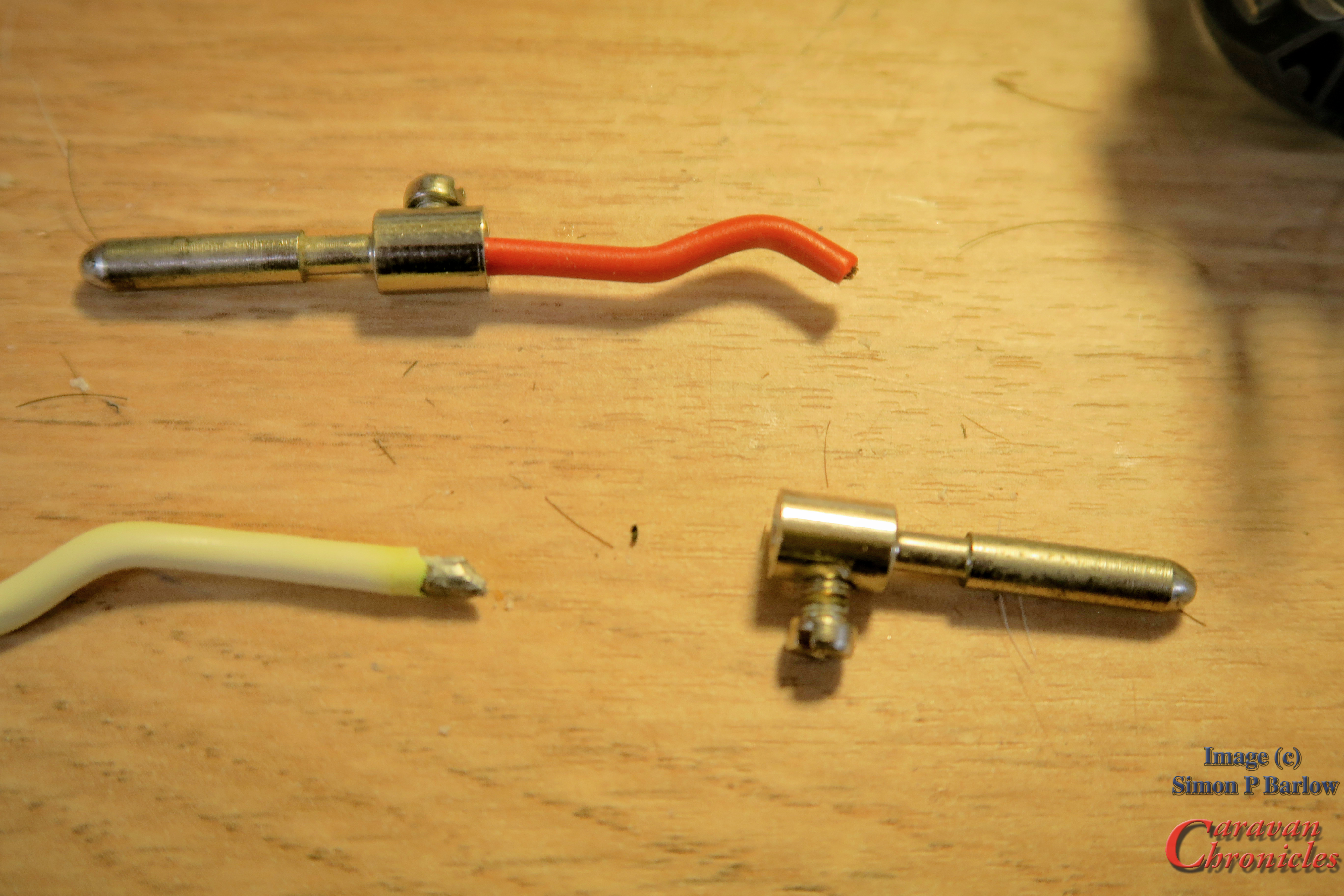
After measuring the resistance of the charging circuit and fridge circuit it was clear there was a bit of an issue. First stop was to disassemble the Dreamseeker’s 13 pin plug. All became clear…. The cable had been terminated in the socket with soldered ends and were suffering corrosion (solder very dull) and cable degradation….. the copper conductors when stripped of their insulation were black. All in all not good.
I wanted to replace the whole 12 core cable with a replacement but unfortunately I didn’t have a length in stock long enough. I usually keep a length suitable for replacing the cable and plug on a normal bumper tow caravan.
The simple solution for the time being would be to cut back as much as I could and install a new 13 pin plug with correctly crimped ferrules on the cable.
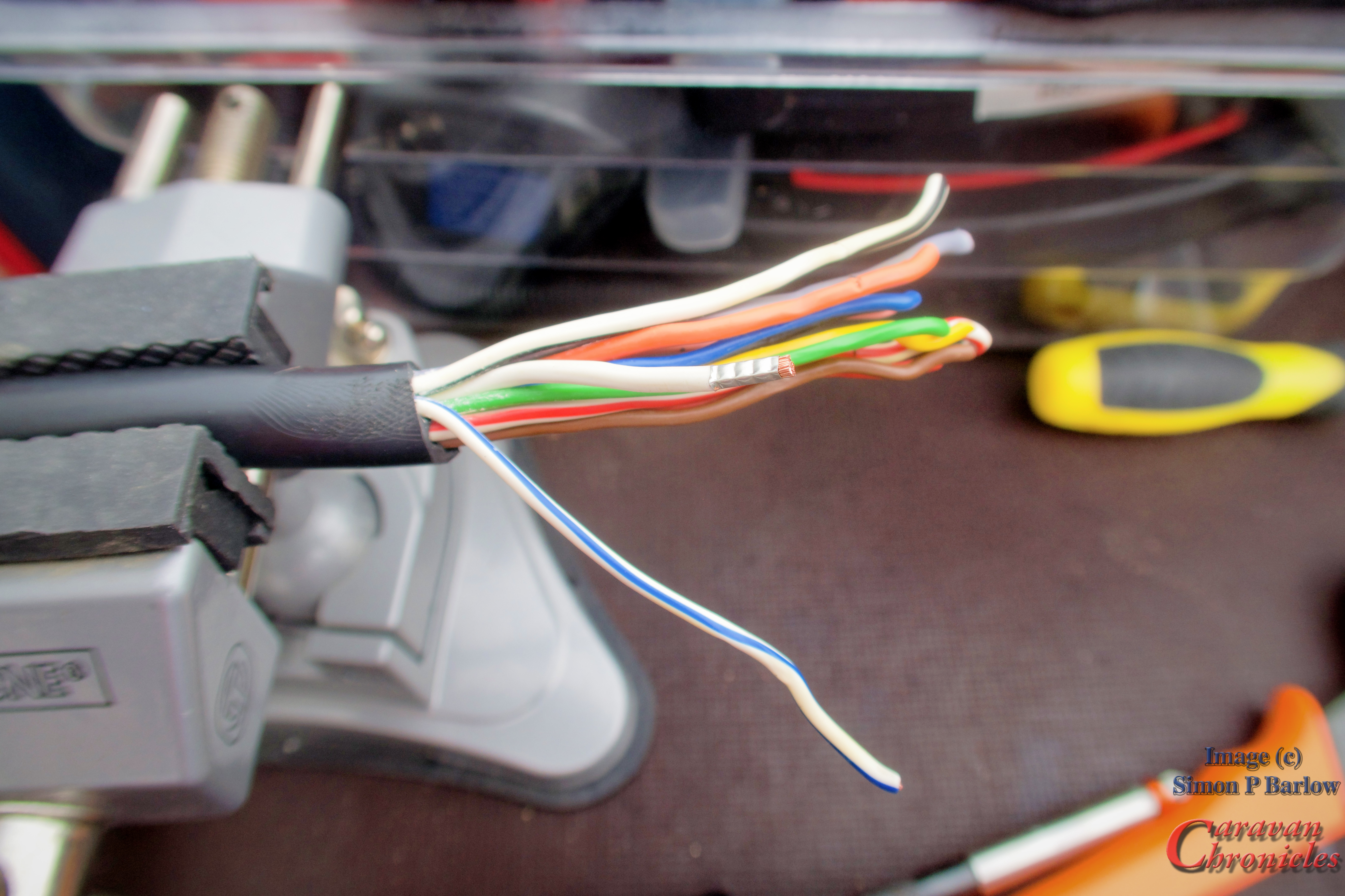
I cut off the old plug and stripped back the protective cover from the cable allowing enough to shorten the individual conductors to the correct length and inspect them for internal corrosion before crimping on the ferrules ready for termination.
The torque setting for these terminations are listed as a minimum of 5Nm to a max of 8Nm so I set my torque screwdriver to 6.5Nm. A happy medium I think.
The new plug was reassembled and I could get on with testing it. At the Amarok I measured 14.7 volts on the leisure battery circuit (same on the fridge circuit) and at the leisure battery I measured 13.9 volts and 9 amps charge, which considering the two 110Ah AGM leisure batteries are at the rear of the Dreamseeker I was happy with the loss.
Something I’m going to try…
While I was doing all this I started thinking (I’d also just seen the price of 13 core trailer cable per metre!) Why are we using this cable?
I have a length of woven kevlar cable sleeve (used in the aviation world) and I could thread my own cable…. upgrading the 1.5mm2 to 2.5 and the 2.5mm2 to 4mm and the “cable” would… (actually is…. as I have made one up now)… a lot more flexible than the existing product as it allowed the individual cables to move and slide past each other. I also used marine grade coated copper cable, so no corrosion of the strands.
4mm2 cable was a bit of a faff to terminate in the commonly available 13 pin plugs, but I believe the genuine ” German Jager manufactured plugs are acceptable for 4mm cable and they even have a crimp terminal version. So I’m going to do a bit more investigating as if I can get 4mm2 leisure battery and fridge circuits from end to end, that will reduce the voltage drop… which is always a step forward.
I’m also looking again at a high current circuit using Anderson connectors between the Truck and 5th Wheel. Currently I’m thinking of a 50 amp circuit with a 30 Amp DC to DC charger installed in the Dreamseeker…. ready for the battery upgrade. (along with a solar install, when I can find a suitable company to work with on that project)
Tourfest Northwest… as arranged by “The Caravan Addys”
Sue and I will be at Tourfest Northwest hosted at Donkey Creek Farm near Warton in May (24th to 28th) drop in and say “Hi”……” see you in a bit“
We have just been for a short stay at Donkey Creek Farm in Freckleton, near Warton…. just up the road from Lytham…. that’s near Blackpool. OK you get the idea. We can’t recommend this site highly enough, in fact in a break of usualness I’m going to write a little review.
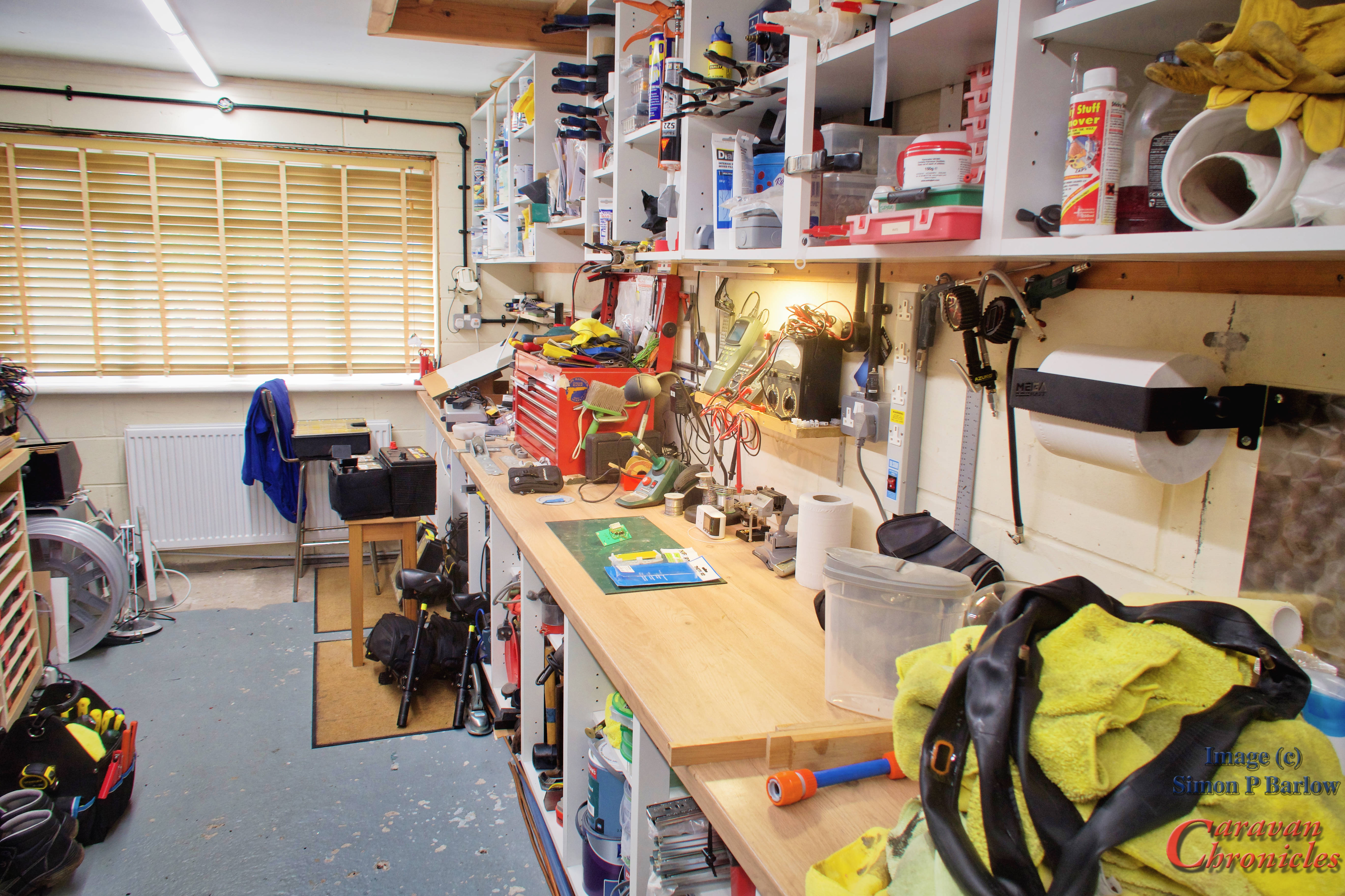
OK back to the main event. We pitched, set up shop and sat down to the usual post pitch brew…. “Ah I thought… I’ll just pop to the loo before sitting down”…. Pushed the blue button on the Thetford toilet and….. nothing, nada, not the slightest hint of a flush pump running. OK we had this once before and it was the fuse that had corroded, probably since it was located in one of the dumbest places possible…. but I won’t go into that. Nope not the fuse, terminal looked clean (probably because I’d given them a coat of protective terminal gel. Phooey it had to be the circuit board.
Using my trusty Swiss Army knife I peeled back the big Thetford sticker on top of the loo… and retrieved the circuit board. It wasn’t looking too clever.
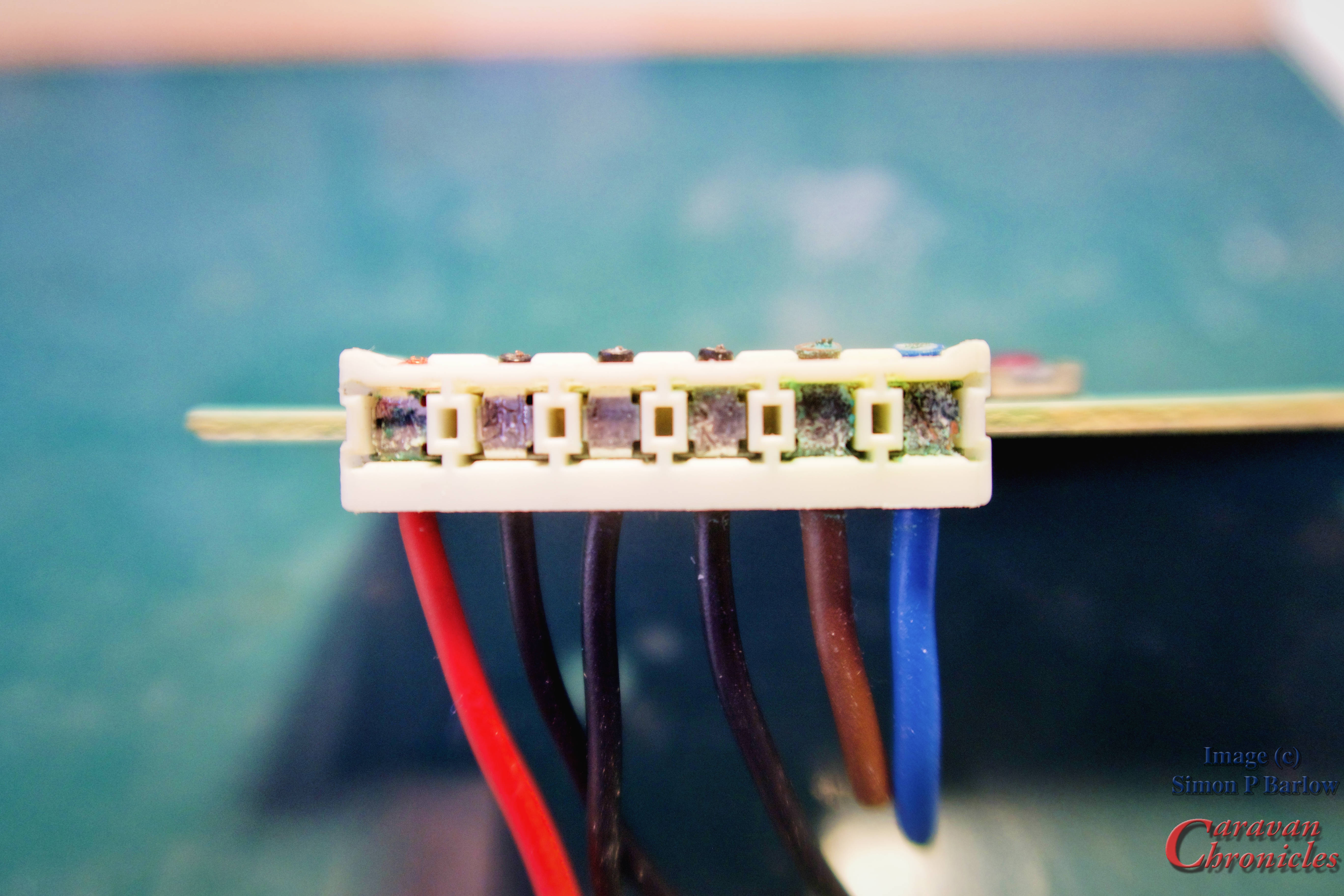
The circuit board was connected to the loo’s wiring via an edge connector… OK for some applications. However on removing the edge connector the copper circuit board tracks had simply corroded away tot he point there was not much copper left on the circuit board.
The other issue was the edge connector was an IDC type (Insulation Displacement Contact) which basically means the wire is squeezed into a knife like ‘V’ in the terminal cutting into the insulation to make the contact.
The upshot of this was the circuit board had corroded, the contact surfaces where the connector contacted the circuit board pads had corroded and the cables had corrosion on their conductors. (in fact I had to cut the cables back by about 60mm to get to good un-corroded conductors)
Going Full MacGyver….
I did have a spare circuit board…. back in the Bat Cave at home….. wouldn’t do much good though as the edge connector was toast. With a Swiss Army penknife…. and my trusty tool bag… Time to do a “MacGyver” and get this thing flushing. I just happened to have a strip of 6 amp terminal block… well doesn’t everyone have a spare strip of terminal block? I cut the connector free from the wiring loom one lead at a time and transferred this across to the terminal block. Once all 6 were moved across it was a simple matter of finding Positive and Negative, jumping the Negative to the Negative side of the flush pump and providing a short fly lead that when simply touched onto the correct terminal on the terminal strip would run the pump.
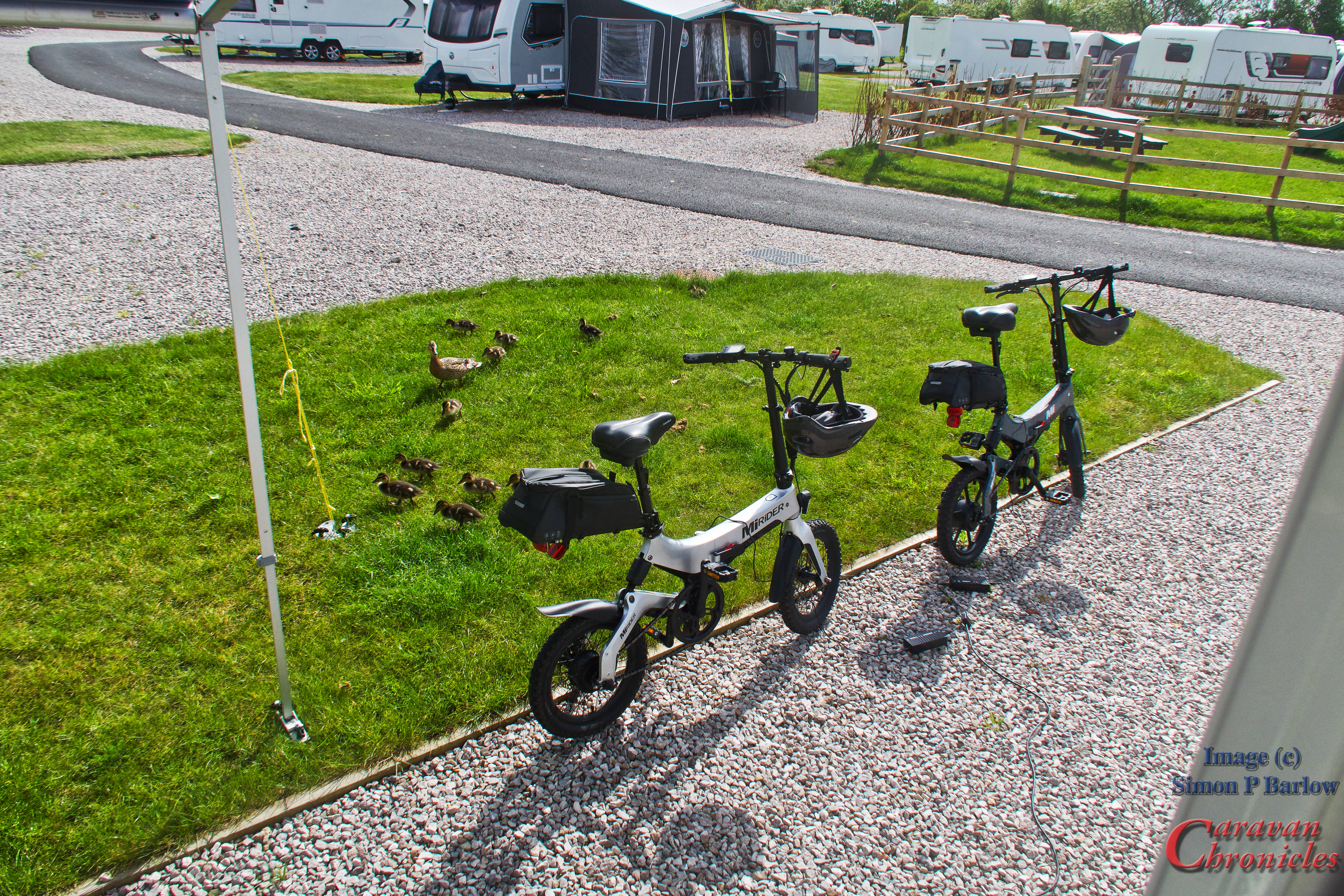
The rest of the stay went well…. got some cycling in to Lytham for morning coffee’s… watched a few planes and watched the wildlife.
Back In The Bat Cave…
Back home it was time to fashion a contrivance that would not suffer the same fate…. heading into the Bat Cave I had an idea…
The terminal strip offered a way to still make the circuit board removable and replaceable but without the drawbacks of the edge connector.
I did try to source an edge connector but as per usual it was something that was a bit of a bugger to locate… unless I wanted 50 of the things shipped direct from China.
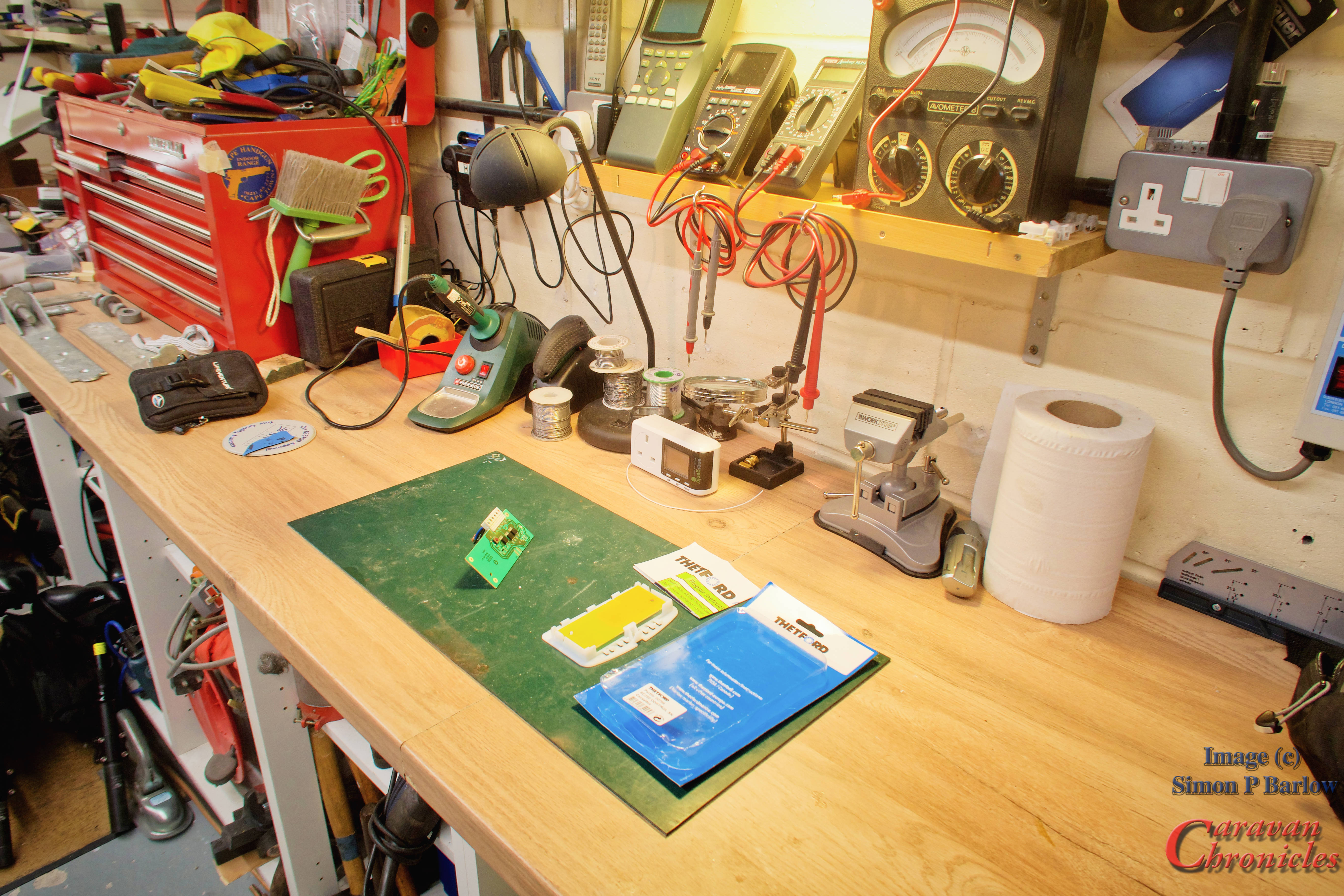
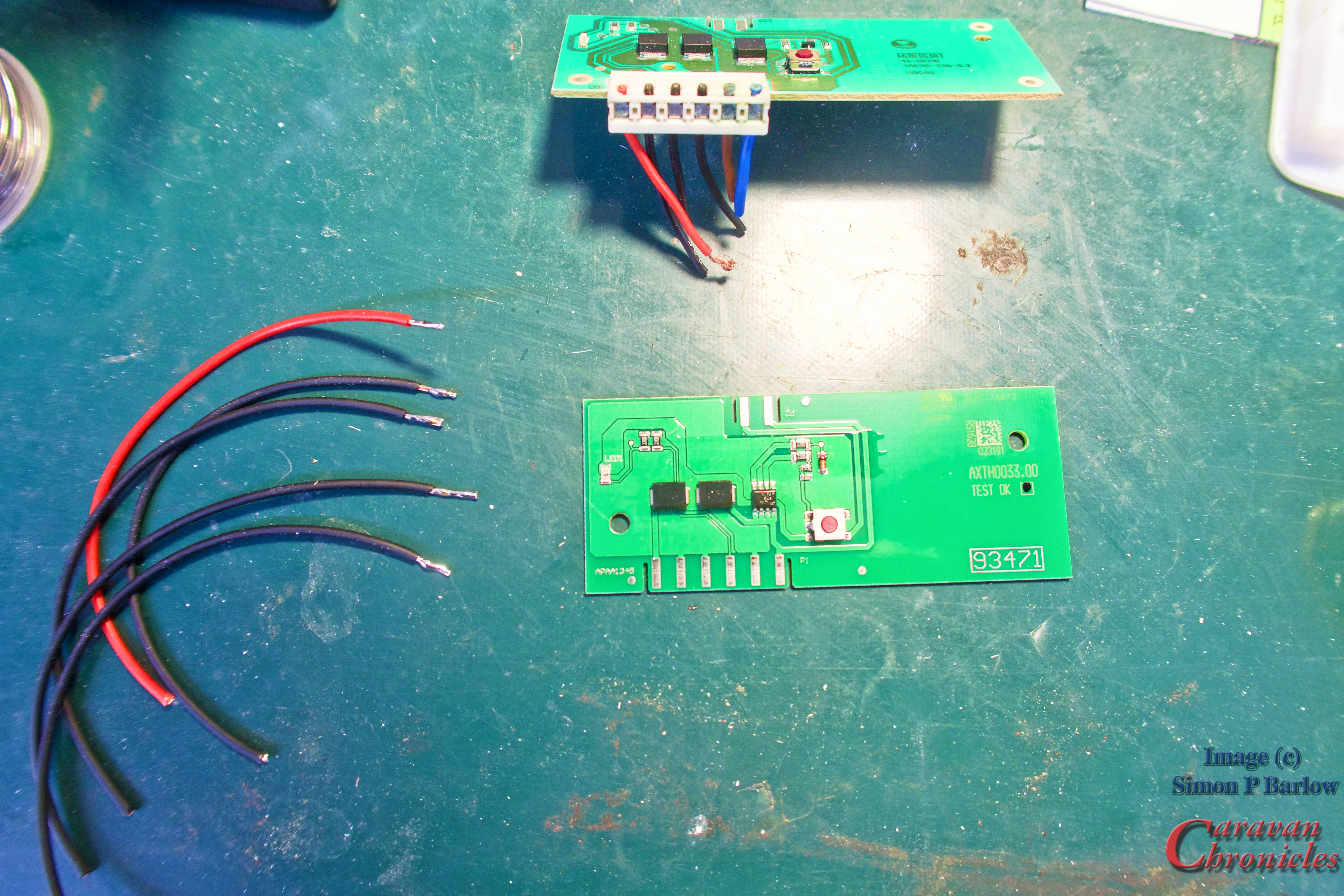
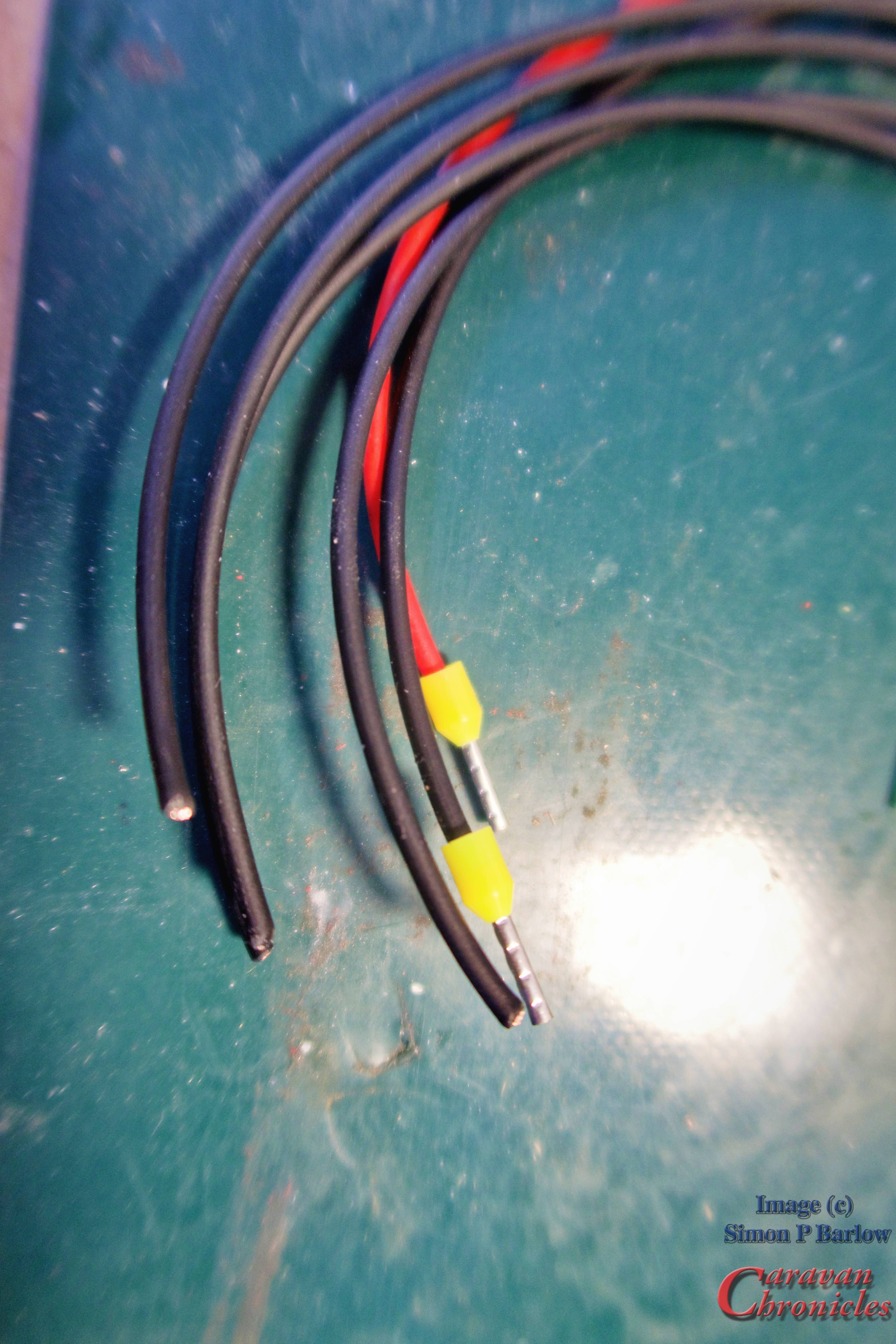
Here is what I cam up with. I’d directly solder short leads onto the circuit board and protect them with a coating of track varnish… something used to coat bare circuit board tracks on prototype boards to stop them from corroding. The short leads would be crimped with a boot lace ferrule after dipping the stripped ends of the cable in a protective anti-oxidising grease.
The finished article prior to coating the soldered terminals with a protective circuit board varnish, and finally assembled back into the circuit board holder…
Installation…
Installation was fairly quick and easy, the wires from he loom that I’d previously terminated on the terminal strip while away in the caravan were removed in turn, cut back to make sure there wasn’t any corrosion in the conductors, dipped in anti-oxidising grease before having a boot lace ferrule crimped on and being fastened into the new terminal strip.
The whole lot fitted neatly into the space below the circuit board and hopefully my little fix will keep the loo flushing successfully for the foreseeable future.
Another Little Job…
A while ago I swopped out the two LED spotlights above the bed (reading lights) for two that were a little less bright and that had USB sockets in their base. This left me with two ‘spare’ LED spotlights that matched those in the lounge area.
We have always thought that the location of these existing spots are great for reading, but not if you are having a meal. The lights provide a saintly halo behind your head but you plate of nom nom’s in front of you in shadow.
So I installed one of the lights right slap bang in the middle of the front overhead lockers points down at the table. So now when we are having a TV dinner with the lights low I can still see what I’m stabbing my fork into. It’s also handy of you want to do one of those artistic foodie shots…. here’s what we are having tonight.
That’s it for the moment…. unless you want to see a picture of a vary lazy cat who didn’t want to get up. Everything is better with a cat… especially if it is Henry.
A while ago I upgraded the lights on our caravan by changing the functions round and added two new LED reversing lights which I can’t understand why I hadn’t done this years ago. In daylight they are bright… and at night they are really bright… retina burning bright according to reports. Reversing into a dark pitch is a lot easier and safety wise having an additional set of tail and brake lights with two large bright rear fog lights instead of the single factory 21 watt light mounted almost as low as you can get on the rear of the caravan is a vast improvement in my mind. You can read about my changes here… “Put Yer Lights On Mate…“
Following that article I had lots of people contact me letting me know they liked what I had done and considering upgrading themselves. Not a clue if anyone did, but that’s how these things go. I did have another email from a gentleman which was a bit different. Now I’ve edited it a bit as it was originally two emails and included a company name and some specific details which I’m sure they would not wish me to publish to the world…. here’s the gist of it though:
“Hi Simon, been reading your blog for a while and I read your post about upgrading your caravan lights. I was wondering if you might be able to help with something we would like to do with our trailers or could put us in touch with someone who can? We have around eight trailers that are used on various locations separately or as a group and are towed by a variety of vehicles, mostly our own but occasionally by contractors. Most of our trailers have additional side lighting powered off the trailers own batteries which are charged from the vehicle or while on site from generators. A lot of our set up and tear down is done at night and we have had issues at dark locations where the vehicles reversing lights don’t really help. Is there any way we could get the side work lighting to come on when the vehicle reverses but could be controlled from the vehicle without any additional switches or alterations to the vehicles but could be turned on and off as reversing on a public road with them on might not be legal”
From an exchange of emails, I do know what the company does and some of the sorts of places it works. They don’t always have access to mains power when setting up or tearing down and would like something that can easily be installed in a trailer without too much alteration to the electrical services. Nothing could be installed in any of the tow vehicles as the vehicles were not always their own and I first suggested a cheap(ish) remote switch that could be used by the driver to turn them on and off as required. I was told this was not an option as the remote switches would likely get lost/damaged or need batteries or be with the wrong crew, some sites they could not use any radio equipment.
Time to put my thinking cat on…
Polo…. always a great thinking cat, sadly no longer with us.
I had a bit of an idea forming. Something I’d seen on a Class A American RV (Prevost I think) was a set of spotlights set in the side panel of the RV pointing backwards and located near the front wheel. These lit up down the side of the RV and the ground to the side when reversing…. I’d thought about adding a couple of simple cheap LED lights to the underside of the caravan between the wheel and front of the caravan angled outwards by about 60 degrees mounted under the floor… so when I reversed they lit up the caravan wheel and the ground it was going over so I could see it clearly at night in my mirrors. I had pondered how to switch this on and off using the Amarok but not add any more wiring between the caravan and vehicle. So I’d already come up with a solution.
Here is what I came up with…
It’s a simple two relay set up. The two triggers for this to work are the vehicle reversing lights and the rear fog lights. The top relay in the box is activated by the vehicle being in reverse with the reversing lights on. The lower relay is activated by turning the vehicles rear fog lights on. Only when these two conditions are met, is there a circuit across the two relays switches made thus activating the work lights on the trailer.
Quite simply when reversing to turn on the work light simply turn on the rear fog lights and the work lights will come on.
Cables 1, 2 & 3 connect to the road lights. Cables 4 & 5 are for the switched load. The cost was around £15 for the components for each unit and that included Bosch relays & sockets, the die-cast box and fuse holder. I guess putting it in a plastic case and using cheaper eBay sourced relays could halve that cost.
I did also think that as an upgrade or option the relay operated by the reversing lights could be a timer relay. Set it to say 15 seconds, then when reversing you turn on the work lights and they will remain on of 15 seconds after reversing as long as the rear fog lights are on. This would give you time to reverse, pull forward and reverse again. Each time you select reverse the timer would reset and as soon as you disengaged reverse the timer would start its countdown again.
High level work lights could be a boon to reversing into dark pitches or storage sites. Image take from the internet, copyright not mine.
It was as simple as I could get it using existing signals from the vehicle that already pass through to the trailer. I guess it could be used to turn anything on using any combination of lights operating from the vehicle.
The wiring between the road lights and work lights is kept separate as I wasn’t 100% sure how the trailers power system worked and how it was connected to the road lights (if at all) The two relays were installed in a die cast box with a grommet for the 5 cables. All the trailers were fitted with one of these and apparently they have all been working fine for several months.
Why did I opt for reversing lights and fog lights?
I wanted something that would not be used generally through the day so reversing on a public road during daylight or even at night the work lights would not illuminate. Running during the day with lights on and your fog lights will not operate the working lights… and if you are running in weather that requires headlights and rear fog light… then I guess having the working lights come on while you reverse in those inclement weather conditions just makes you more visible to everyone around. So apart from that I don’t think that you will cause a danger on the road with this set-up.
So…. I think I might just have to install one of these on my caravan…. just in case!
Low level scene lights down the side of the trailer can be just as effective as high level work lights. Image taken from the internet, copyright not mine.
Its a fairly simple DIY job to build a box and install it without too much messing about with the original wiring. Now someone asked me about getting the orange side marker lights to flash in time with the indicators…. and remain as side markers when the indicators weren’t being used. Is this something I need to put my thinking cat on for? Let me know in the comments.
One thing about being retired… you have way too much time to think about things. One thing that has been wandering round my grey cells for the last few months relates to an email I had September last year and it was from someone who was fitting out a van and had a few electrical issues, which I managed to help him remotely sort out the problems.
Something that struck me was an off the cuff remark about being able to separate the vehicle side electrical system and the habitation electrical system but still have them work together.
So here is my thoughts and a bit of a sketch (you all know I like sketches) on a possible but workable solution…
Taking a bit of inspiration from the world of aviation and how systems are split into individual bus systems and master bus system that can be combined and isolated as safety procedures require, I thought about how the current wiring on conversions could be improved.
Installing two fuses, one on each pole between the vehicle and habitation, would limit the maximum current between the two systems… the habitation system and the vehicle system. I’ve called these the “Habitation System Isolation Fuses”
In my sketch, the DC to DC charger is a 50 Amp unit, so I have sized the fuses at 50 Amps… (I’d actually install Tyco W23 thermal switch circuit breakers… more about that later) Fusing the positive (live) is normal, but adding a fuse in the Negative / Neutral line is not normally considered. However I have a sound rational for doing this.
Looking at the right hand side – the Habitation Side, we can see that there are two LiPo batteries located some distance apart and connected by a battery bank interlink cable. The feed from the battery bank goes from one battery via an isolation switch and 200Amp fuse to power the habitation equipment and the return is via shunt to monitor the battery bank to the opposite battery. The interlink Positive cable is fused at each end with a 200 Amp rated fuse. All that is pretty normal.
However there is the possibility that the battery interlink cable could be routed through bulkheads or the cable from the battery bank via the battery isolation switch could be routed through vehicle bodywork bulkheads to a distribution point. If this cable was to chafe, there is the potential for a direct short or intermittent / low resistance short to the vehicle ground. As this battery bank is fused at 200 Amps, you could end up warming up a bit of vehicle cabling to the point of PVC fumes filling the van or a full blown fire. Remember you can stick weld steel with 150 Amps!
By inserting a fuse in the Neutral /Negative line – the Habitation System Isolation Fuses, you have effectively fused any potential short to ground from the habitation side battery pack to 50 Amps which if a direct short will blow the fuse before any of the 200 Amp fuses have started to even warm up! Note… if your DC to DC charger is only 30 Amps then these two fuses would be rated at 30 Amps.
Could This Be Improved?
Well yes, everything can be improved. Upgrading the Vehicle Charging Isolation Switch to a double pole would mean when you are parked up, turn the switch off and the habitation electrical system is completely isolated from the vehicle electrical system… down side is some solar chargers have a trickle facility for the vehicle battery (normally connects to the vehicle side of an isolation switch to work and relies on negative continuity between the two systems)… and one day you will forget to turn it on when you are going to do a days driving.
Load sensing on the Neutral / Negative at the Habitation System Isolation Fuse would show if you had a drain from the live side of the habitation system to vehicle ground.
Prerequisite …
The big prerequisite to doing this is of course you haven’t been a cheapskate and only used one wire to supply equipment on the habitation side and used the vehicle body as the Negative / Neutral path.
Short story… someone contacts me, can’t get a device working properly. Tracing the power side, no issues, tracing the return path… some resistance. Turns out the body panel is bonded on to the vehicle and there is no electrical continuity between the body panel and vehicle neutral… so in order for the 5 watt interior light to work, the vehicle manufacturer installed a 75mm long flat beaded strap between the body panel and the section of chassis it is glued to. I recon this strap was good for about 2 or 3 amps… so when the fridge was running and the 5 amp accessory powered up the combined negative wires that were screwed to this body panel slowly heated up the bit of flat braided bonding strap installed by the manufacturer.
Morel of the story…. if you are supplying electrons to something…. also install a route for them to go home! Don’t rely on others to have done it for you. They don’t know what you were planning to do when they designed the thing!. (OK Physics majors will now be sitting upright, drawing their keyboards close and about to compose a long winded essay on why I’m wrong… Yep I got it… I know electrons, negatively charged, move the other way).
Not using the body as a conductor has been known about for a long time by the Professional Audio Boys… you know the ones on You Tube… stereo bass kicks in and the girls….. hair…. that’s a better word… jiggles about with the sound pressure driven by speakers that consume enough energy that even Doc Emmitt Brown would raise his eyebrows at ( I wonder if that where he got Jigga Watts from?)
Tyco W23 Circuit Breakers
On aircraft anything that is powered by electricity goes through circuit breakers and nearly all fall into two types… W23 / W31 or W58.
W58 are pop out breakers that you push in to reset, but W23 and W31 are switch breakers. W31 look like a toggle switch while W23 have a button that can be pulled out to turn it off. I like W23 style breakers….
They are made for 240 volts AC, 50 volts DC and have been around for 40+ years. I’ve flown planes built in the 60’s that still use the original CB’s in them. Now they are mostly made in Mexico or China but are all to a very well established spec and testing standard. You can get them in 1, 2, 3, 4, 5, 7.5, 10, 15, 20, 30, 40 and 50 Amp ratings so you can best match them to your system. The spec sheet even tells you what to torque the cable screws to when installing. Personally I’d replace all fuses with these things…… oh yesssss…. I do like a good CB panel… pat on the back if you guess the aircraft type.
Conclusion…
Well I’m not an expert in 12 volt systems and although I have designed and worked on aircraft electrical systems, that really means nothing in this context. These are my thoughts on something that may or may not be needed but it’s how I’d probably go about doing things.
P.S.
If anyone from INEOS is reading…. I love the new Grenadier and especially the aircraft style panels…. quite happy to do some tow testing for you…. hello…. anyone there?
I’ve had quite a few people email me asking for more information about the Victron system for a caravan that I was planning mentioned in the previous post. As this seems to have generated a number of questions, rather than give detailed answers to each one I thought I’d post the drawings. For the moment it’s on hold but here are the drawings.
While Victron would seem the obvious choice, there are a number of recent new products from Sterling Power that have rekindled my interest in the project…. watch this space.
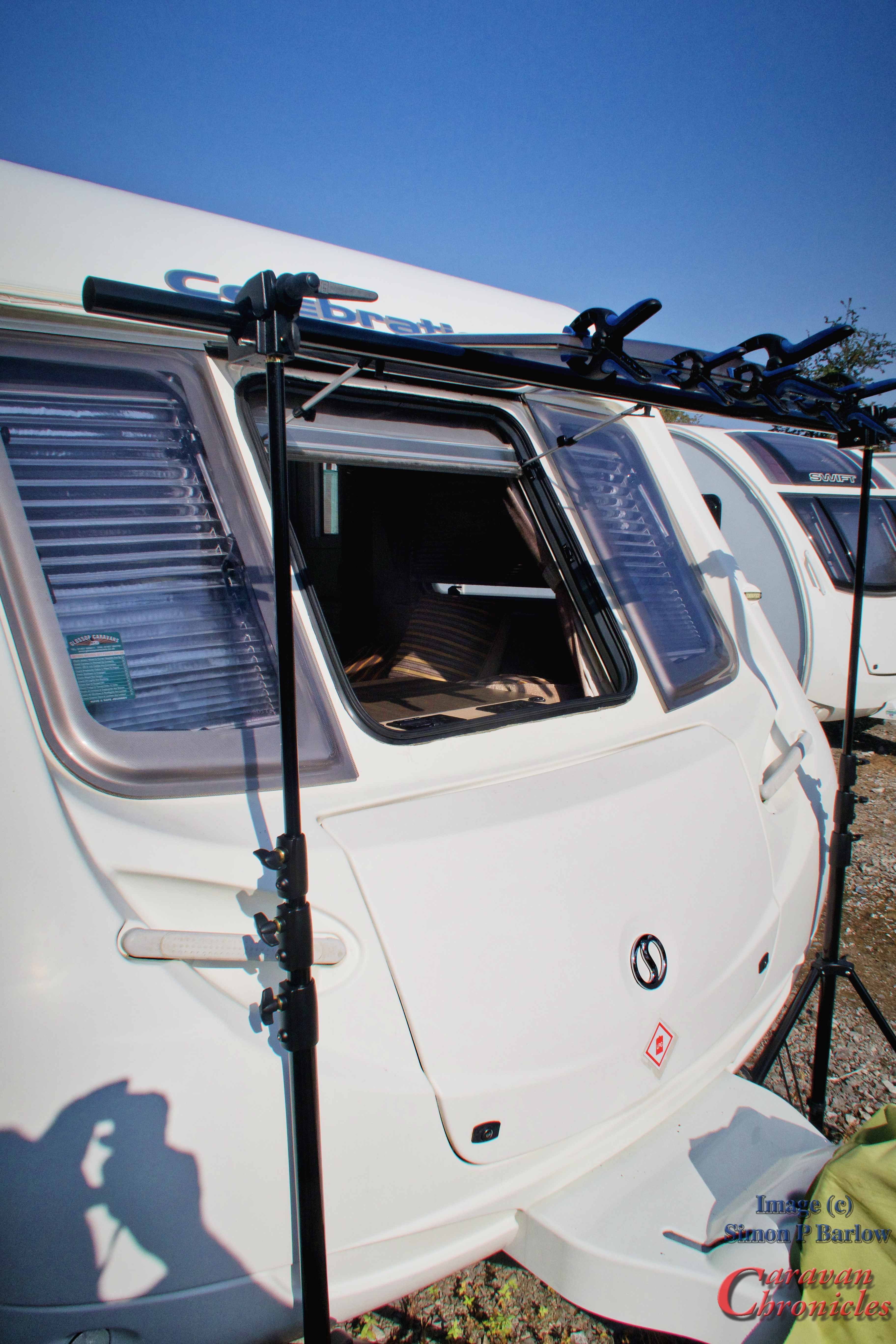
I’d got a few little jobs still outstanding from our big clean a week or so ago. The big one was to repair the front window. When we were cleaning the caravan I noticed that the bottom edge of the central window was starting to separate. After some lengthy procrastination I’d have preferred to replace it but given the hefty price tag and the “It will be January next year at the earliest before we can get you one” type answers from suppliers and removing the window and shipping to off to a company for repair would cost almost the same as a replacement.
It can’t be beyond a diy task to repair. I did a bit of searching for information relating to repairs and one name kept popping up as the manufacturer of the product used to bond the two sheets together…Bondrite Adhesives Ltd.
After reading through Bondrite Adhesives Ltd website a couple of times to work out exactly with adhesive I’d need I ordered their WC112 acrylic adhesive. The 50ml size was £12.10 plus shipping and VAT bringing the total to £20.52. It arrived within 24 hours of ordering, was really well packaged and came with a detailed technical sheet and guidance notes.
I’m not going to do a blow by blow account of how to repair a delaminated window… as I don’t know if this is even going to work, but my first step was to support the window as flat as I could. The standard recommendation is to remove the window lay it on a flat surface and go from there. I didn’t want to remove the window as all I had to repair was the lower edge.
Improvising I used two stands with a cross beam clamped between them to hold the window horizontal. This should take any flexing stress caused by the window stays out of the equation…. Hopefully!
To hold the gap between he two sheets I used three long needles from syringes… this allowed me just enough wiggle room to slide some blotting paper with a bit of isopropanol alcohol to clean out any contaminates. I’d already tested this to make sure it was safe and it does evaporate very quickly.
You are advised to lay down a 5mm bead of glue… as this was going to be difficult between the two sheets of partially bonded plastic I opted to use a wide bore syringe needle on the glue bottle which allowed me to squeeze glue into the gap… it was a bit fiddly but I managed to achieve what I thought would be the right amount. Sliding the three previous inserted needles out to allow the sheets to come together I used some fairly light clamps to hold the pieces together while they cured. Bondrite do caution about NOT using an excessive clamping force as it can lead to crazing of the sheets.
The data sheet advice is that handling strength is achieved after about 3 hours at 20 deg C. I covered up the glued area with microfibre cloths to protect it from the sun and had a sit down with an iced coffee and a sammich.
Next Job…
If you read my previous post “Put Your Lights On Mate…” then you might have picked up on my request at the end for any recommendations for a UK supplier of good quality replacement LED bulbs. Well Peter Farnham posted in the comments section and recommended Classic Car LEDS Ltd ( https://www.classiccarleds.co.uk ). A couple of days later I dropped them an email with a few questions and Duncan replied back with some details. A few more exchanges of emails ended up with me ordering replacement LED bulbs for the new fog lights, indicator lights and stop/tail lights. This is not a sponsored post and I paid the required number of beer tokens for these.
Not much to say on changing the bulbs over… what was noticeable was though they did have a bit heft to them… they seem really really well made. No flexing, solid and just had that feel about them that made me go “Mmmm” while nodding slowly…. almost in a Joey Tribbiani moment.
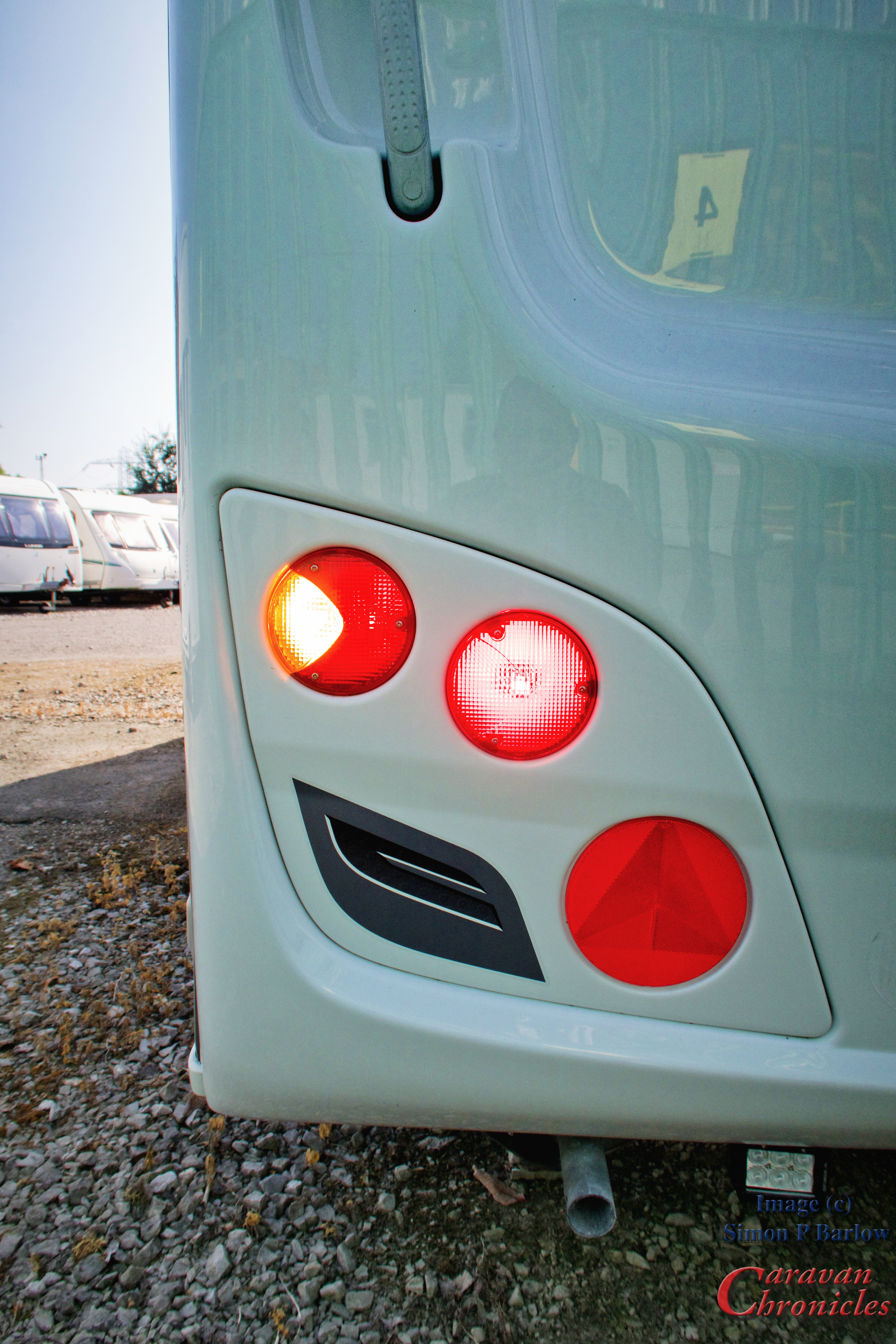
I did try to do before and after photos to compare the light output…. even tried a short video with one side changed over and the other side on conventional filament bulbs… all failed…. not as easy as it looks in strong sunlight even though the caravan rear was in shade. However the photo above is one side converted over. This is showing the indicator, tail light and fog light lit. The indicators are really bright. Having the LEDS the same colour as the lens works well. The tail light is a strong red and bright while the fog light looks washed out and white… it’s down to the fact that it is so bright its over exposed…. the exposure is correct for the indicator and tail light but the fog light is amazingly bright.. and red.
On the VW Amarok I haven’t had any canbus warnings… I even plugged in my reader to check… all good and no strobing or hyper flash.
To say I’m chuffed with these LED bulbs is a bit of an understatement… if you suffer from rear light envy as you follow one of those gloriously illuminated trucks down the motorway, drop Duncan an email at sales@classiccarleds.co.uk and tell him I sent you. Sort out your rear lights and never again have someone with four megawatts of light bars and spots flashing you and shouting “Put Your Lights On Mate” as they simulate a starship going into warp drive passing you.
Another small job next…
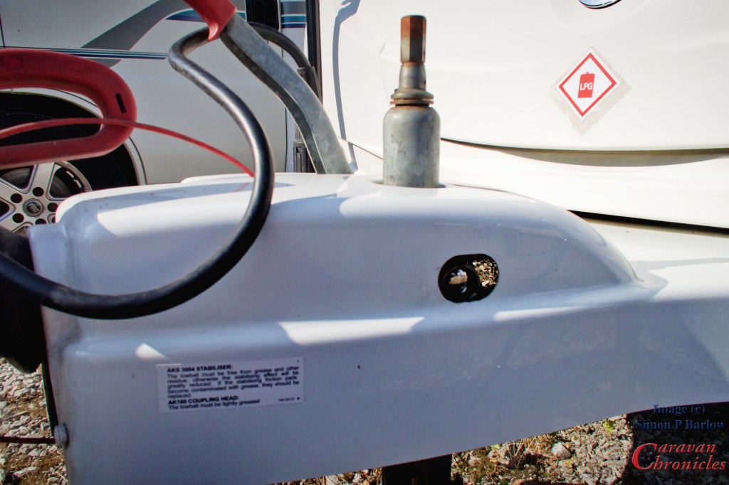
I’d had this gadget for a while and I can’t remember where I got it from. I think it was from a caravan shop at a dealer near York that we visited a while ago.
Simply it’s a security head bolt with a hardened shroud that replaces the normal jockey wheel clamp handle. When it’s installed it is flush with the A frame cover and pretty difficult to get to. It comes with a short handle and socket that fits the security bolt head. I did try with a couple of sockets but the shroud makes it almost impossible to even knock a socket on with a hammer. So if anyone want’s to nick the caravan they now also have to contend with the hassle of getting round my jockey wheel clamp. As I always leave the caravan nose high in storage you can’t even pick it up and drop it on to a tow ball. Hey if it makes them try elsewhere… it works for me.
Thinking about the next step…
This is going to be a big one. I’ve been planning this for a few weeks now and it involves two or three drawings… some detailed planning and I’ve been checking equipment specs in detail. The last stage was to sit and stare at the space available in the caravan and work out Tetris style how it is all physically going to fit in and how much of the existing kit will be removed. More to come soon!
Back to the window…
OK I bet you have been wondering how I got on. Well after nearly five hours of curing time I disassembled my contraption holding the window open and it seems to have worked OK. I can see that it has bonded all along the bottom edge. I could have put a bit more glue in at one spot and needs a light clean up all along the bottom edge to remove what has oozed out. I’ll leave that for at least another 48 hours before attempting to gently sand it off.
All in all I’m pleased with the result and hope to see that it will stand up to the test of time.
How many of you have driven behind a vehicle in less than ideal conditions… going dark, raining or foggy… and uttered those immortal words “Put you lights on mate” in the vein hope it will do some good only to approach a bit closer to find that the lights are on and are less effective as a couple of Ikea tea lights in jam jars. That is the feeling I get with a lot of caravans. In my opinion a lot for rear lights are less than ideal. In this day and age some of the drivers out there need all the help they can get as they even struggle to notice a big white box in front of them in bright sunshine let alone in inclement weather or in the dark.
Our caravan like a lot of other Swift caravans looks great from the rear with nice big lights and reflectors. Reflectors are good if the following driver has turned his headlights on and not been too busy texting and simply relying on the DRL’s to light the way. The big reversing lights will surly let the driver and anyone else behind know you are reversing… but about as useless as the aforementioned Ikea tea light in a jam jar when reversing at an angle into a pitch at night. The rear fog light however deserves a special mention… the single rear fog light…. can you see it… the tiny Lego brick sized rear fog light… the red thing in the middle down low… difficult to spot on a stationary caravan in daylight let alone from a distance on a road in fog. Mind you when that bit of wire in the bulb warms up it will blind you… honestly it will…. eventually… when you get so close because you didn’t see it from ten metres away.
Its time for a change. An upgrade if you will… to allow me to shine a beacon of light towards all that follow. But… and here’s a the big thing… I have to keep it looking nice. Everyone likes a nice rear don’t they.
OK, I searched for all the replacement options. Swift don’t make it easy. The two panels that the lights are mounted in don’t come out, well not easily and I was cautioned about even attempting to remove them. Changing to smart round LED lights was out. Then it struck me… the reversing lights could become fog lights and I would install new reversing lights. I’d towed a trailer a while ago that had football stadium sized reversing lights and wow what a difference it made. One of the first things I did with the Amarok when we got it was to install LED work lights under the rear bumper as reversing lights and that was a huge improvement so I ordered another set from the same company as I’d fitted to the Amarok.
A bit more searching I found the exact lenses for the existing lights in red to turn the reversing lights into fog lights.. it was actually cheaper to order a pair of complete lights than it was to order two replacement red lenses… I’ll never work that one out.
Ok how was I going to wire this lot up. I made a couple of brackets that fitted under the caravan allowing me to mount the reversing lights up close just inboard of the rear steady jacks. This would offer a modicum of protection from road debris thrown up by the tyres. These could be wired to run off the old fog light which would now become a junction box and the reverse lights would become the fog lights, so simply switching the reverse light and fog light cables over at the road light fuse box in the front of the caravan would have everything working correctly.
I also angled the reversing lights out slightly. I wanted the centre of their light pool to be along an extended side line of the caravan so that looking through my mirrors down each side of the caravan would be the centre of the lit area. This hopefully would provide the best angle of illumination when reversing and performing a reversing turn onto a pitch.
“Hang on lads… I’ve got an idea”
Cue the music… no, no doors were blown off during this mod. Right what if the new rear fog lights could be my brake lights when they weren’t being used as fog lights?
A simple diode blocking bridge using two diodes could do this quite easily. Routing through my electronics spares I found a bag of 10 Amp diodes which would easily cope with the task.
For a quick solution I used two strips of terminal block and built a quick blocking bridge. What happens now is applying the brakes powers up the brake light circuit and the fog lights. The diode in the fog light circuit stops me back feeding current to the tow vehicle fog light circuit.
Turning on the fog lights powers up the fog lights and the diode in the bridge stops it powering the brake lights in either the caravan or back feeding to the tow vehicle. Really simple and when testing I didn’t have any canbus or other errors thrown up by the VW Amarok’s management system. The existing (and original) brake and tail lights work as normal.
I’ll have a look at coming up with a better solution than using two lengths of terminal strip and probably build something in a small electrical project box so it can be mounted securely.
As far as I can tell the changes I’ve made all fall in line with the lighting regs for trailers. While I’m 99% sure, there is always the possibility that I could be corrected and shown the error of my ways and point out I have missed something in my reading of the regs. I’ll let you know.
The next thing…
I’m trying to find some good quality bright LED replacement bulbs for all the rear road lights. I have some, but I suspect they are not correctly marked. If anyone has any recommendations for replacement 25W and 5/25W bulbs that they deem are good options to look at, especially if they are correctly marked, please let me know in the comments. If you are a company that sells LED replacement bulbs and think they are the good enough to pass the Caravan Chronicles testing department (we don’t actually have a testing department… its just me) then challenge me to break them!
Safe travels everyone… and “PUT YOUR LIGHTS ON MATE”
A few days ago we were at the Manchester Caravan & Motorhome show and we think that finally we may have found our next caravan. I posted on Twitter couple of photos and said something along the lines of “Now anyone that reads the blog will know we have been looking for a new caravan for the last couple of years and finally the @CoachmanCaravan Laser 665 ticks nearly all the boxes…“
A follower on Twitter – Venomator @Venomator tweeted back “I would be very interested to know what box/es remain unticked then?…” so this is a bit of a reply really.
My “Lithium Ready” sticker…note the ticked box!
One of the biggest things I have been looking out for on any caravan or motorhome is a sticker announcing that the charging systems installed are suitable for Lithium chemistry batteries. So many people have been asking me recently about changing over to Lithium and what’s involved… well quite a lot actually. There is not that much difference between a motorhome or a caravan when it comes to changing over to Lithium.
The existing shore power charger built in to most motorhomes and caravans is not lithium friendly and will probably result in either damaged lithium cells or a battery that is never really charged. So the inbuilt charger will need to be swopped out.
The solar chargers on most (not all) leisure vehicles can’t be programmed for lithium, so that will need to be replaced. And finally the vehicle charging system, which currently on most production leisure vehicles be it motorhome or caravan is not suitable for lithium batteries so a DC to DC charger will need to be installed.
All this adds up to a bit of a job and a fair chunk of beer (or wine) tokens on top of the price of a Lithium battery. I have seen lithium batteries that are advertised as direct replacements and can be dropped in place of an existing Lead acid wet cell or AGM battery but this would imply that they have charging circuits built into the battery and careful research shows the same battery and part number offered by a different vendor with no such claim to be ‘drop in’ replacements. So beware.
As I really wanted to start off a new van with a lithium set up (I can get around 360Ah of lithium for the same weight as 110Ah of good quality lead acid) but the down side is I’d have to virtually rewire the charing side of a new caravan. I eagerly await one of the big caravan manufactures to offer a “Lithium Ready” product and maybe they would like to use my label!
I don’t think it would be that difficult to achieve and due to production volumes, the additional cost would only be marginal. I expect that (or hope!) that one of the aftermarket companies such as Sterling Power or RedArc would offer something that might be a cost effective ‘box’ to achieve a changeover.
I still would like caravan manufacturers to actually go out and look at a site full of caravans being used. I can’t understand why they don’t move the electrical hook up and water at least behind the axle so it would be closer to where the EHU post is. One thing I find is having a VW Amarok which is one of the widest pickups on the UK market, on some pitches if we are using the Aquarol it’s damn near impossible to squeeze down the side. Moving everything to the rear would make it so much easier… well for us it would.
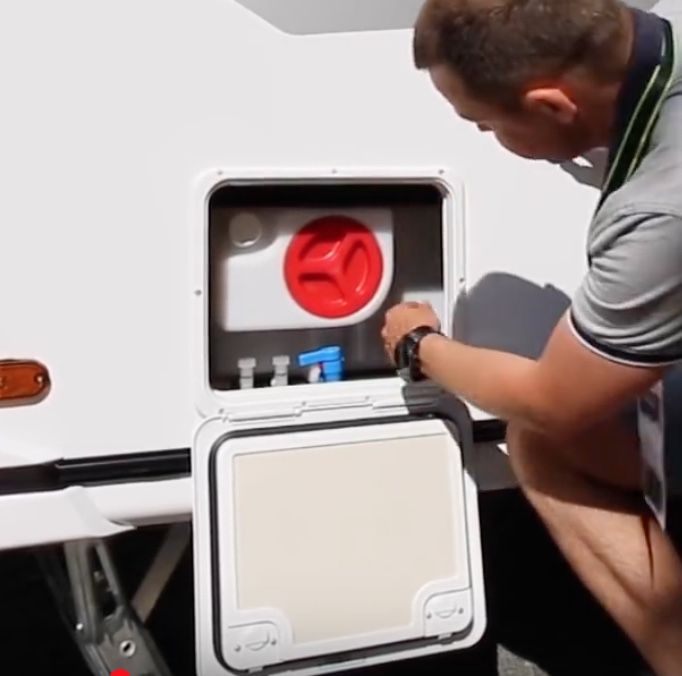
While I’m on the subject of EHU’s & water connections…. Instead of cutting lots of small holes in the sides of our vans for water and 16 amp connections… do what our American cousins do… locate everything in one locker and save on the routing out holes in the sides and adding plastic doohickeys with sliding or hinged covers. I do like the fact that some caravans now have the battery stored in a floor compartment.
240 volt connection, water inlet and valves to switch between internal and external water all neatly located on one locker with access panel for hose and cable through the floor. All located to the rear of the caravan… and in a European caravan too!
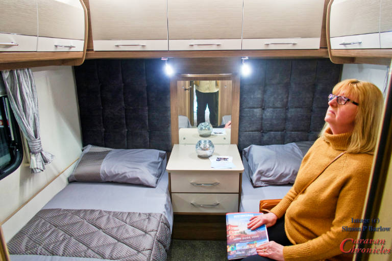
The other one that missed the tick box was the lack of being able to sit in front of a mirror…
Not a deal breaker for me… but Sue thought that if they had made the mirror so it could swing round either way to face each bed that would have been ideal. Some of Swifts offerings have got it spot on with a mini dressing table. Coachman however have conveniently located a socket for hair dryer/straightners. I did wonder about having a small stool or seat spanning across the two beds… but think the mirror swivel is a much better idea. Maybe it’s something that could be added as an after market item using a swivel TV bracket maybe”
Now… anyone know where I can buy some cheap lottery tickets…. hello… anyone….
My email box tends to get a wide variety of questions covering all sorts of subjects. The most frequent one is to do with wiring and electrically related problems. Sometimes trying to diagnose issues via email and a few photos is a bit of a challenge, but hey who doesn’t like a challenge! One thing that I do see a lot of is electrical work that is…. well, quite frankly not up to scratch in my opinion. So here is my attempt at a basic guide.
So many projects start by adding one or two things… extra 12 volt outlet here… maybe another light and then something else comes along that needs adding in. Before you know it you have a mess of spaghetti that the local Italian restaurant would be ashamed of. It is all too easy to fall into the trap of adding circuits to existing fuses…. or installing a new fuse and a few weeks later adding another circuit to it as it’s easier than installing another fuse.
Start with a plan…
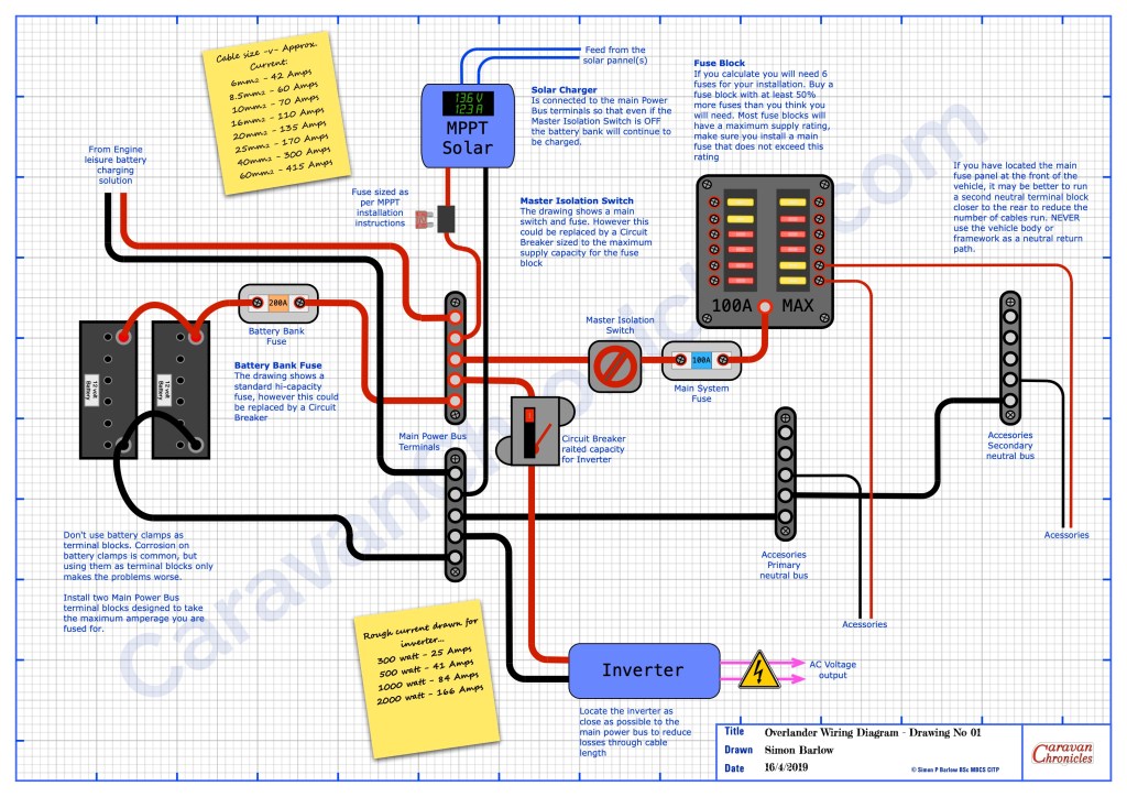
You can download these and other drawings from the Electrical Drawings page in the drop down menu under “Document Library”
You need to draw out how the major elements are going to connect together – leisure batteries, solar charger, DC to DC charger, inverter and include all the big fuses, buss bars and fuse box. Don’t think about where any of this goes for the moment just get the basic layout and how everything interconnects worked out. It might take a few goes but paper is usually cheaper and less frustrating than sorting out the mess afterwards.
Once you have all that figured out you can start working on the details… just how many fuses will be needed… and what ever number you come up with add half as many again as a minimum. Having a few spare fuse positions that maybe never used is way cheaper than in twelve months time having to install an additional fuse box. A this point you can start adding details…. what size cable is needed for each link, what sort of fuse box do you need.
You can also now start to think about specific facilities you might need. For example, many overlander vehicles will have a button on the dash that when pressed and held down activates a high current relay that links the house batteries to the engine cranking battery. Very handy to have… jump leads are not much use if you are 200Km from the nearest vehicle. If your only trip ‘off road’ however is the muddy car park at the local car boot sale than maybe not a priority.
Don’t use the vehicle chassis as a ground.
Modern vehicles are constructed using different materials and quite often panels and sub frames are glued together. Back when virtually all the panels were spot or seam welded steel, using the body and chassis as a ‘ground’…. which really isn’t a ground but the neutral return path… this was acceptable. However now, sections can be glued together and are often sub assemblies of aluminium and other light weight materials bonded together. Just because you see a neutral bonding point (earth terminal) don’t assume this is is capable of being a suitable point to bond the neutral side of a circuit or accessory you are installing. Modern vehicles often have small bonding straps between sections that can carry the current that the vehicle manufacturer rated the bonding point for. Adding additional equipment and accessories might exceed the original design spec.
I did see a spectacular failure due to a 3000W inverter having it’s neutral lead ‘grounded’ in the rear of a vehicle. Running at about 2000W the neutral side was trying to ‘return’ a current of about 170 amps through the body of the vehicle, which lead to serious damage to some of the vehicles wiring and a number of vehicle components… and a ‘repair’ bill of nearly £1500.Putting a riv-nut in a body panel that is mastic bonded to the body is not a suitable negative bonding point!
Additionally a number of vehicle circuits are now negative switching or operation and installing additional equipment or accessories could have unforeseen issues. Always from any accessory or piece of equipment you install, add the neutral return path back to a suitable single common point or buss bar you install for the purpose and connect this directly back to the leisure battery.
Ideally all the ancillary leisure circuits should never rely on any of the vehicle wiring and the negative side of the leisure wiring should only ever connect to the negative side of the leisure battery.
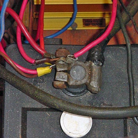
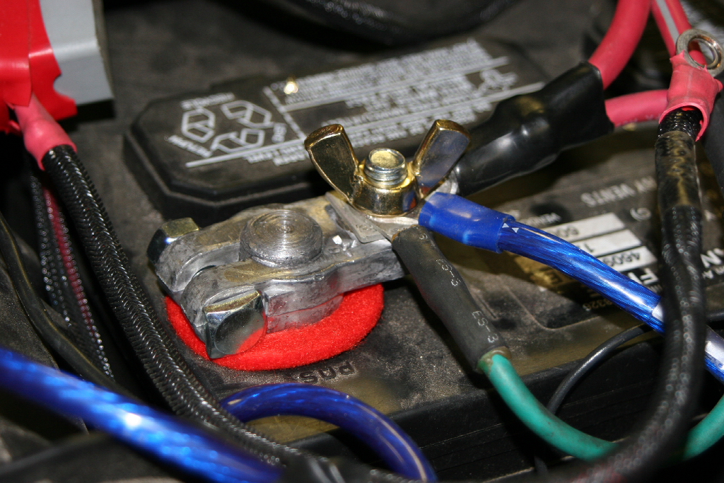
Don’t use battery terminals as a junction post.
Both the leisure battery and engine battery should only have connections that lead to either in the case of the positive terminal a master fuse /circuit breaker and isolator switch. The negative terminal should only have the connection to a master negative terminal point or buss bar.
Nope…..Not OK…. it’s a terminal not a junction post (image from the Internet)
If you want to install any sort of battery monitoring, it is convention to install the shunt on the negative return to the battery between the negative buss bar and the negative battery terminal. If you have multiple circuits terminated on the battery terminal it makes future changes and upgrades, including installing a battery monitor very difficult.
Just NO! (image from the Internet)
Using the battery terminals as connection points for multiple services also makes fault finding very difficult. Each circuit may or may not have it’s own fuse and it’s difficult to isolate circuits….. plus I’ve had enough sparks flying round when trying to disconnect a battery because someone did not install an isolator to know that it’s only a matter of time before one goes ‘pop’.
Just because it’s shiny…. NO!!! Not OK (image from the Internet)
Please, just don’t do it.
Have a think on this. If you had to go to an auto electrician to get a fault traced and corrected, they would immediately put at least an hours time on the invoice just to figure out what was going on with all the cables on the battery. Also, If you don’t have a battery master isolator installed, get one installed now. It’s a safety item that must not be missed out. Having the ability to quickly turn off all the leisure circuits in an emergency might just save you from the unthinkable happening.
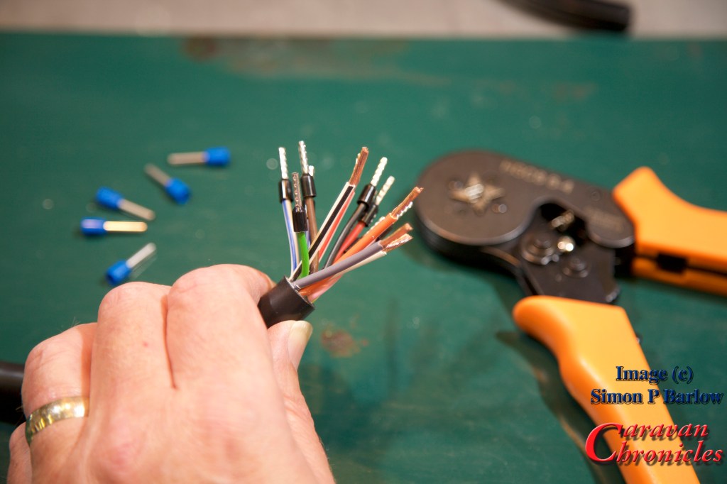
Cable Termination
Every cable should be terminated. Period. There shouldn’t be any cables in an installation that don’t have a crimped (or soldered) termination. Even if it’s a screw terminal such as those found in joining blocks or 13 pin plugs.
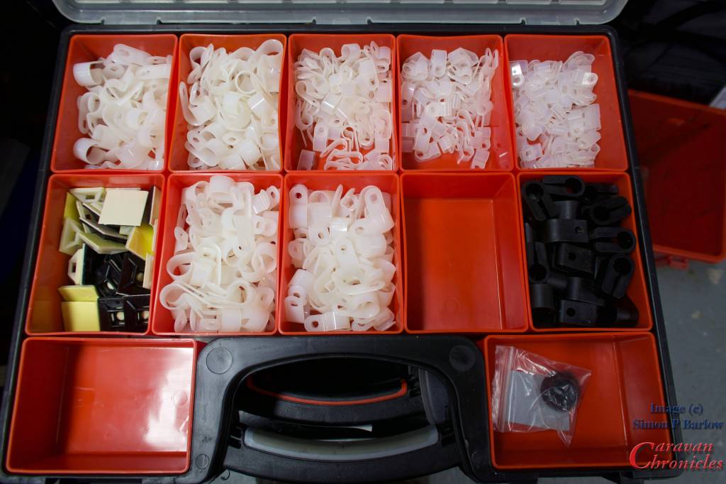
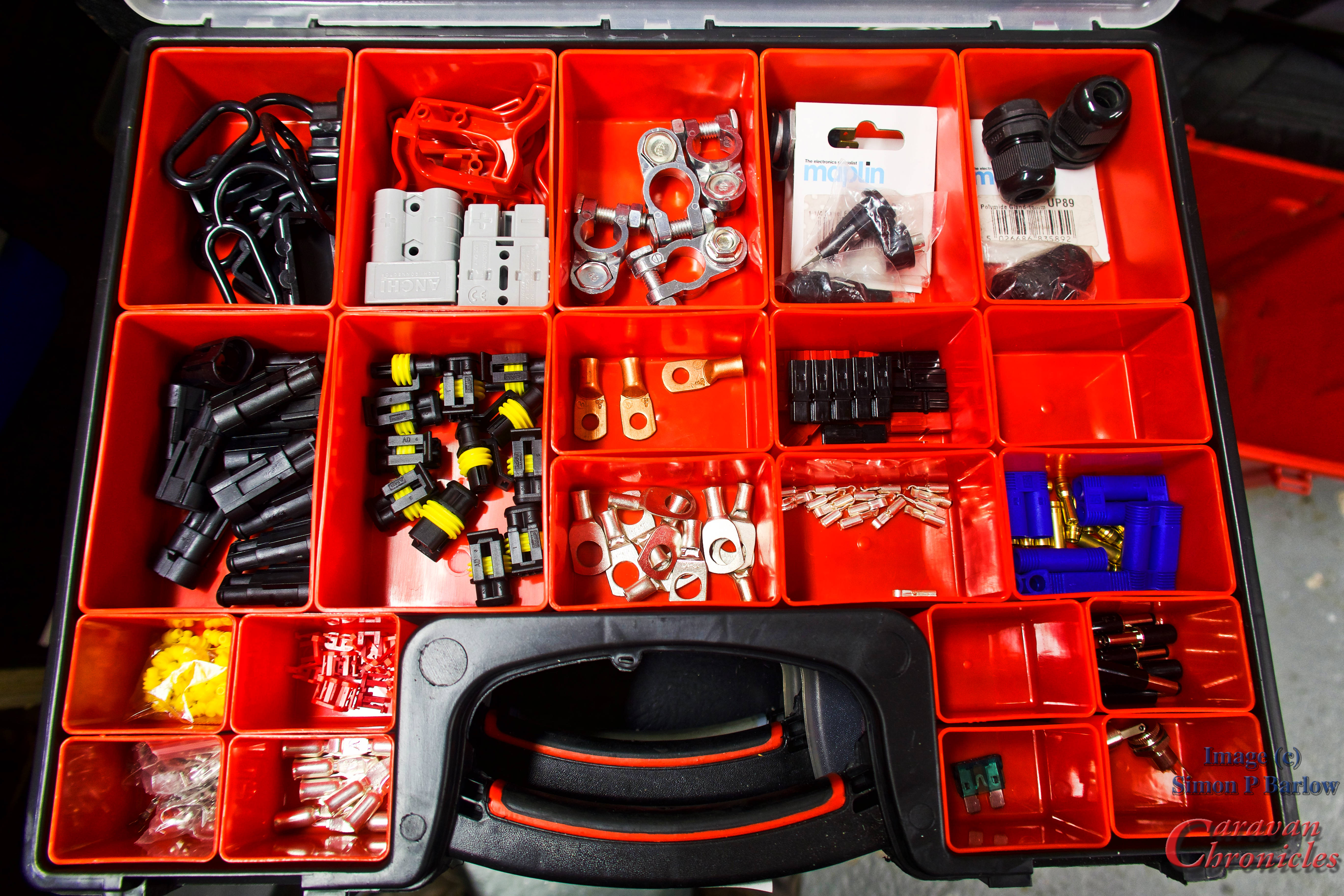
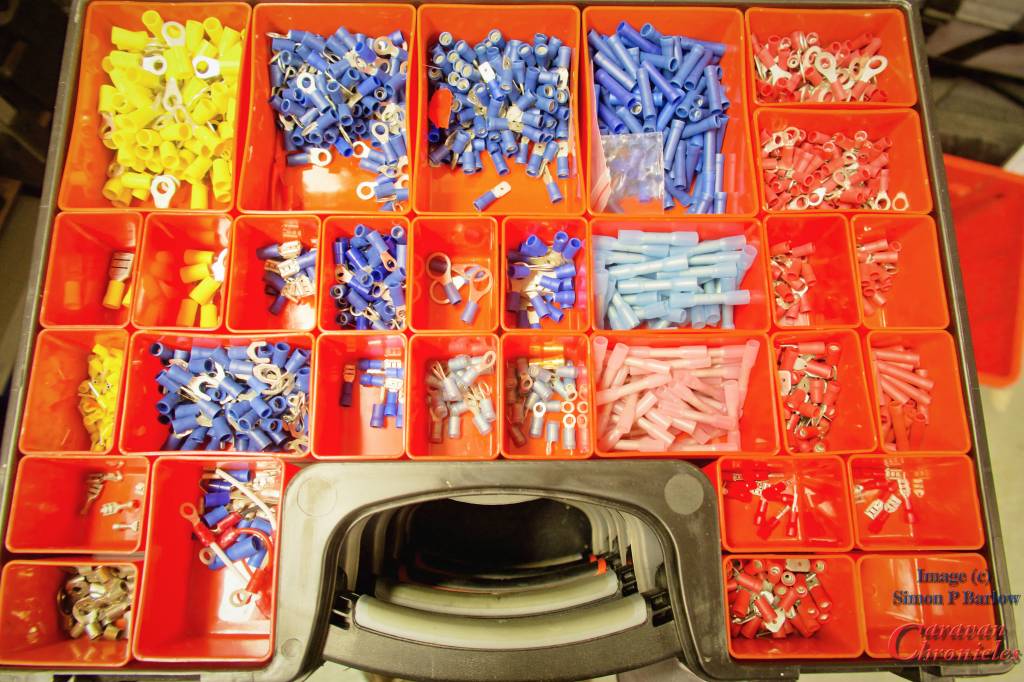
If you are embarking on a wiring project, its always best to start building up your stock of terminals. I usually buy selection boxes of terminals on line and supplement these with bags of single type connectors for the more commonly used ones. To keep everything organised tote organiser boxes are my preferred option.
A few of the 20+ of my storage boxes with wiring components
There is nothing more annoying than running out of the something and its always just as you want to finish a project off so you end up cutting corners.
For some of the larger cables, if you don’t feel up to making your own terminations there is usually a local auto electrician available that will terminate them for you for a small charge. However, a crimping tool that will terminate up to 50mm cable is not that expensive – around £27 and will probably work out cheaper in the long run. I’ve a link to the one I bought via Amazon and regularly use in the SHOP page.
Get the size right…
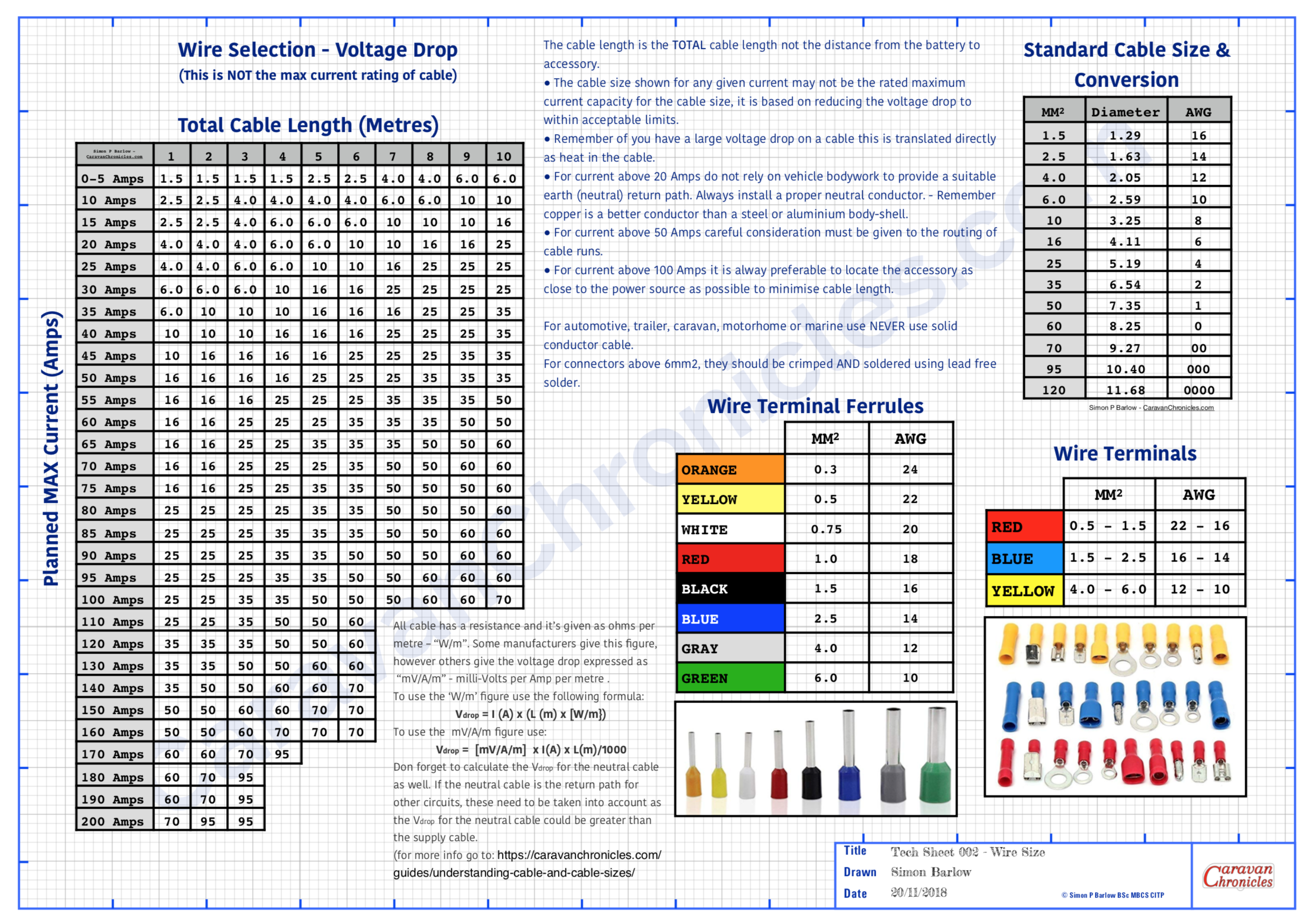
Selecting the right size or gauge of cable is critical. There are two factors that determine what gauge of cable to use for a installing any particular circuit. The maximum current that’s going to be drawn and the length of the cable. Once you have selected the right size cable then means you can select the right size fuse for the circuit. Never fuse a circuit greater than the current capacity of the cable.
Handy wall chart of cable size and terminal sizes.
You can download these and other drawings from the Electrical Drawings page in the drop down menu under “Document Library”
I generally tend to list what is going to be installed, then work out all the gauge for the cables for the circuits. From there it’s easy to see which is going to be the most popular gauge and rather than buy several different gauges of cable try to select a limited selection of gauges.
Always go for the safe option of over specifying the gauge of cable for any particular circuit. If it’s a 10 amp circuit and you have used cable suitable for a 16 amp circuit, it doesn’t mean however you need to use a fuse greater than the 10 Amp circuit requires.
Something else to consider too. Most 12 volt cables are copper, however if you are installing them in a less than ideal environment, such as a boat, you may want to opt for tinned copper cables. These are far less susceptible to cable corrosion. Even in the best marine installations I’ve seen copper cables corrode through in less than a couple of years.
Cardinal Sin! – Never ever use two smaller cables to make up the equivalent of one larger capacity cable. You would be surprised how many times I’ve seen this… sometimes done by “professional” tow-bar installers when reported poor leisure battery charing or poor fridge performance is reported and the voltage drop is too great.
Wiring Looms – wrapping it up properly!
Dressing cables into looms is not difficult nowadays. There are many options available on the market to help you produce a professional looking finished product. I personally like for looms within the vehicle using a felt finished looming tape. You don’t wrap it so it overlaps but at a sharp enough angle so as it spirals round the cable bunch it leaves some of the cables exposed.
Felt is good as not only does it keep the loom together, it allows quite a bit of flexibility and prevents cables from rubbing or banging on flat surfaces making a noise.
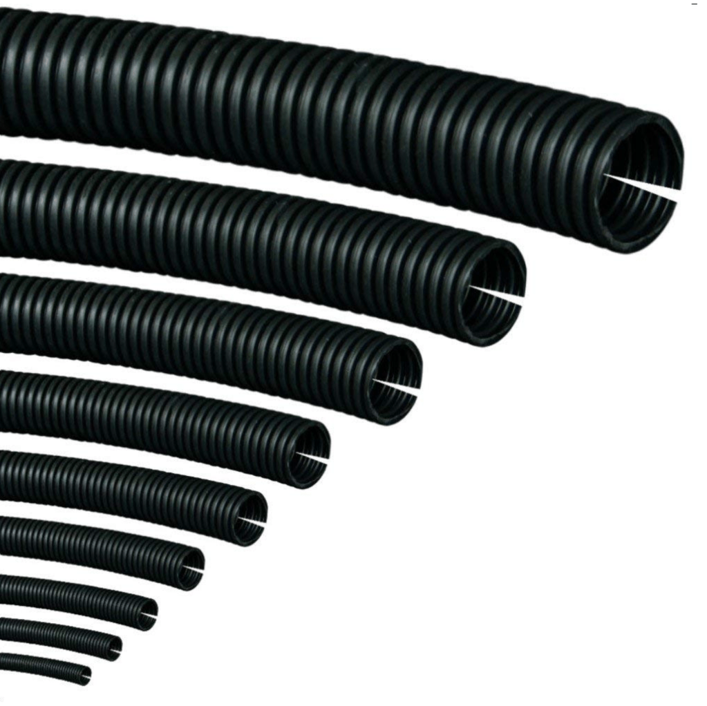
For any cables outside the vehicle body there are two options depending on use. In the main I’d go for split tube conduit. It’s available in various sizes and can be bought in either cut lengths or rolls. The other option is to use self amalgamating tape. It looks like ordinary PVC tape but as you wrap it round you stretch it and it releases a chemical which when overlapped onto its self becomes a permanent bond, effectively making a sealed tube. It is generally however fairly inflexible. Both have their place.
Anything in the engine bay or underneath the vehicle I use split tube and generally only resort to self amalgamating tape to seal inline joints.
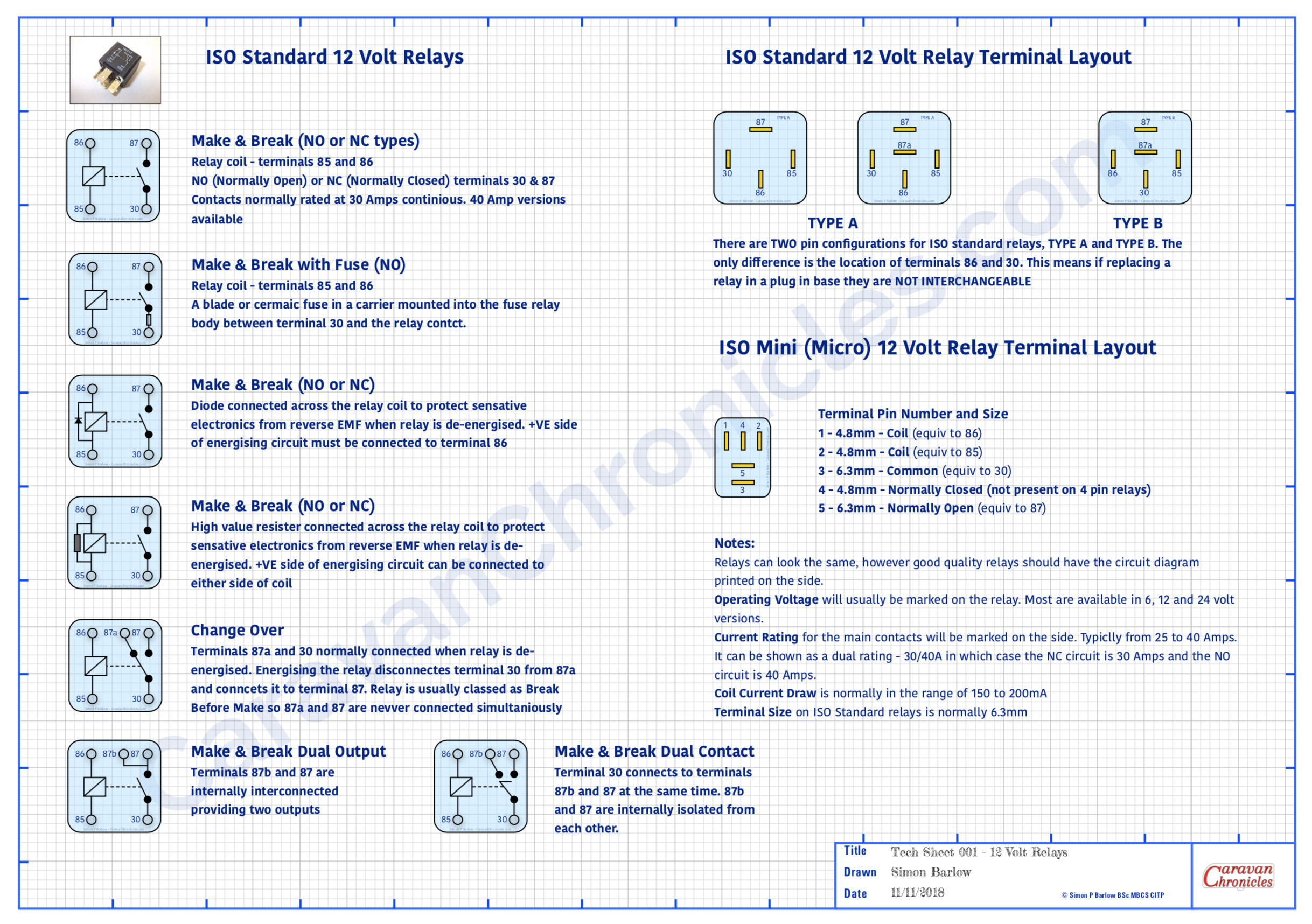
Relays….. yes or no?
For me its Yes. I much prefer locating all the relays in one place therefore minimising the amount of heavy cable. By using relays to do the heavy switching you can use smaller and sometimes more attractive switches. I have in the past used 7 core trailer cable to connect 4 switches including LED indicators back to a relay bank rather than make up a custom wrapped loom.
Handy wall chart of relay types
You can download these and other drawings from the Electrical Drawings page in the drop down menu under “Document Library”
It also makes tracing faults easier, as it’s simple to test if a switch is working, you can hear or sometimes feel the relay operating as you operate the switch. Its unusual to have a fault with a relay but quite simple to test… just unplug and swop over with a known working relay. If all the relays are located together it makes this task and testing the feed to the relays so much simpler. From that point all you need to check are the two wires going out to the device and the device itself.
Obviously some circuits don’t require a relay or if it’s designed to be turned on for a long period… such as a diesel heater, then adding a relay will just increase current draw, albeit small, on the leisure battery. A bit of common sense can easily determine if you should opt for a relay or not.
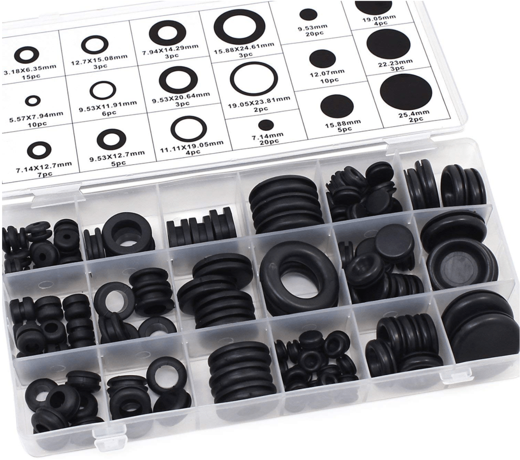
Grommet?…(no not Wallace’s friend!)
Whenever a cable or cables pass through anything solid you should use a grommet. You would be surprised at the amount of damage I’ve seen to cables due to either not installing a grommet to an insufficiently sized (too small usually) grommet.
When ever I pass either a cable or loom through a bulkhead for example I like to supplement a grommet with a bit of heat shrink sleeving over the cable as well. Even passing a cable through an existing grommet from the engine compartment to the interior, adding a length of heat shrink sleeve won’t do any harm.
There’s a link to these in the SHOP… only about £7 for the full box.
Having a handy selection of grommets available before you start threading wires through is far better than trying to install protection afterwards. You’d also be surprised at how many cables I come across that have been damaged while pulling through holes in metal and wood panels. Always better to start with a grommet or two! Where a cable or loom passes through a grommet, it’s aways best practice to try and anchor the cable or loom either side of the grommet to something solid using “P” clips. This will reduce the chances of ‘fretting’ with the movement of the vehicle.
While we are on grommets…. a quick note about cable-ties (zip-ties). Stop doing them up so tight! I’ve come across cables cable-tied to a chassis rail so tight that the cable-tie has cut into the insulation and is fretting the conductor inside. Cable-ties are generally made out of a harder plastic than the cable insulation so will over time wear away at the insulation.
Get yourself a cable-tie tool that not only allows you to precisely control how much tension you put on the tie but also cut the end off so that there isn’t a wrist slashing booby trap lying in wait for some unsuspecting person. I use a fairly cheap pair (left). I think they were around £8. So not really expensive. But they make a nice neat job of installing multiple cable ties with the correct tension and the ends cut cleanly off level with the lock tab. You can buy ones that have a tension dial built in so you can set them to a pre-tension, but I find after a bit you know just how much to squeeze the handles to get the correct tension.
So what is the correct tension… well if you are doing them up so tight an elephant could dangle on the cables then that is too tight. They should be tight enough so as not to slip but you should be able to spin them round the cable(s).
Cable-ties really should not be used to make looms or anchor cables or looms to anything solid. If you want to make a loom, wrap it in specialist loom tape. If you want to anchor cable or a loom to something solid use a “P” clip. If required… use a length of heat shrink to make the loom a tighter fit in the ‘P’ clip.
I know you are dying to ask…. when do I use cable-ties? Well generally at the installation stage to get things to stay in place before installing P clips or if I have to run a new loom along the same path as an existing loom, I generally opt for cable-ties to hold them both together (as long as the original is suitably anchored to support both)
While we are talking abut cable-ties… I have seen the worst kind of mistakes in the use of them. It is not OK to cable-tie anything to brake lines, fuel lines, vacuum lines, hydraulic hoses, coolant hoses or steering components (yep one bright spark cable-tied his front LED light bar wires to some of the steering components!)
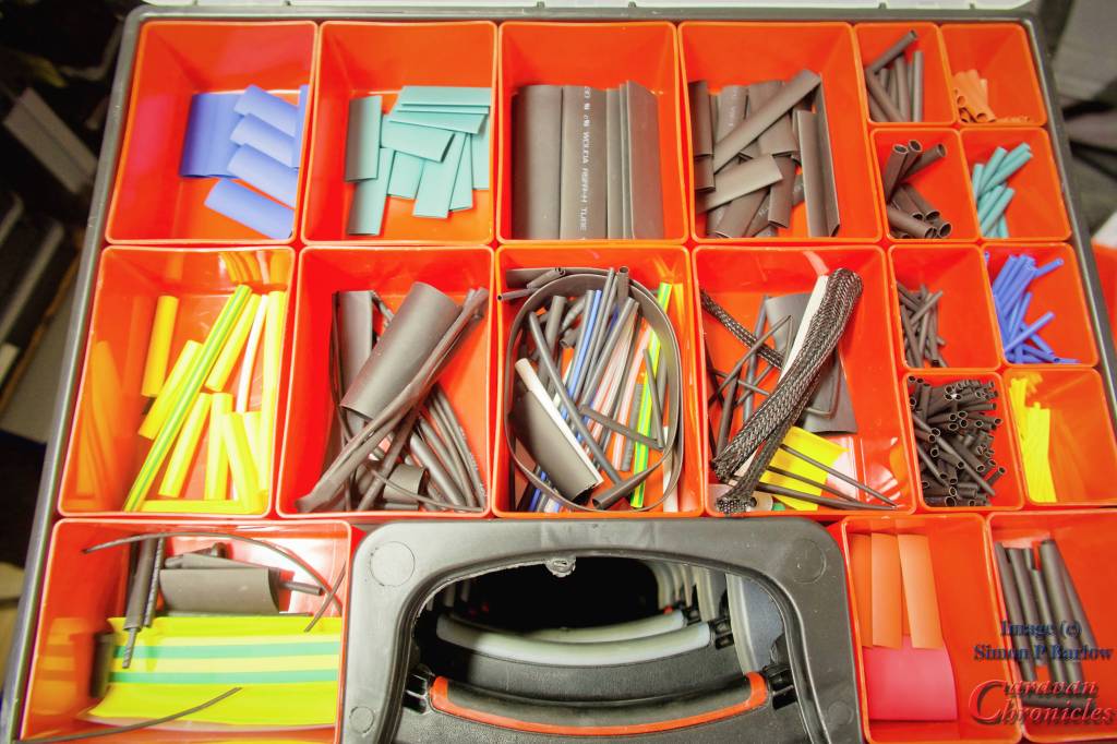
Heat Shrink Tubing
An absolute must have in my opinion. There are two main types – plain and pre glued. The plain are the main one you would use, while the pre glued are great if you have to over sleeve a connection to make it waterproof. As you heat up the pre-glued type, the glue softens as the tube strings and bonds to the cable as everything cools. They can be a little more rigid when installed, so make a service loop in the cable. The finished covering is usually waterproof enough for brief submersion if done correctly.
Having a selection of sizes and colours is handy and assortment boxes of multiple sizes and colours can be bought on line cheaply enough. In the workshop I use an old paint stripper heat gun on low power as I find that is more controllable than a flame.
Bridging the gap… something in the future?
Although not so common in the UK, in Australia and the USA wild camping (boon docking) is probably as popular as campsites. To this end trailers and caravans usually have much larger battery capacities than anything found in Europe. It’s not uncommon to find outfits with 600 to 800Ah battery banks recharged mainly be solar, buy increasingly (especially in Australia) an additional bridge between tow vehicle and trailer is made using heavy duty “Anderson” connectors and cables capable of supplying upwards of 60 Amps from the vehicle to the leisure battery bank.
With the cost of lithium batteries reducing almost daily, I can foresee very soon that light weight lithium batteries will be installed in caravans. The down side of this currently and trying to retrofit Lithium is the existing charging setup of current European vans is not really suitable for looking after these type of batteries. We have a Sterling Power Wildside unit installed in our caravan which allows us to charge any type of battery chemistry, including lithium when connected to the tow vehicle. The draw back is the caravan’s inbuilt charger is only capable of wet lead acid or AGM. I think that a high capacity DC to DC charger installed in the vehicle and an additional cable to supply the caravans battery banks may not be too far away. It’s something you might want to keep in mind for the future. It’s something I’m looking into currently.
Well, that’s a bit longer than I anticipated and there is still a few things to cover. If you made it this far…. take a toffee out of the jar… well done! If you think I missed something or would like me to cover something specific, drop me a comment below.