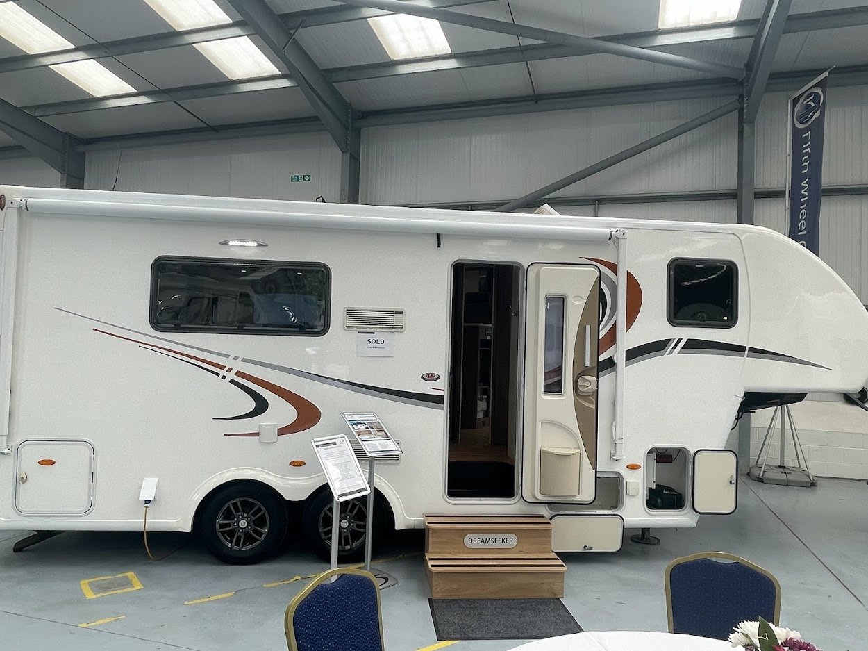
I think one or two of you might have already guessed… we have bought ourselves a 5th wheel caravan. (Was it the pickup that gave it away?) So here it is…
Why a 5th wheel?
We decided that as we have now both fully retired that we would like to change the style of caravanning from a few days in one place then returning home to more of a few days somewhere…. then a wander somewhere else for a while then maybe move on again over a period of a couple of weeks before returning home. We can (and have) done this with our old caravan but packing up and then pitching again was becoming a chore for multiple stops. So we started looking at motorhomes as these had the advantage of more payload and a bit more elbow room. Something else we wanted to do was store our e-bikes inside rather than secure them outside when on site.
However when the cost of a suitable motorhome started to creep well above £100K…. we dismissed all the UK built motorhomes as most are just a caravan dropped on a chassis with an engine. So A-class it was. We looked at Carthago and really liked the c-line but my wallet went into cardiac arrest. We could cut costs a little if we cut some of our requirements and on top of that adding a vehicle that we could tow. It meant we were looking at the thick end of £150K. On top of this would be the cost of a towed vehicle and the decision to either flat tow or trailer. I believe that flat tow can be a bit of an issue in some European countries, but that might be hearsay. The yearly cost of two services, MOT’s, Insurance was also a big factor.
We started looking again at caravans with a new vision. The problem was for me, writing this blog for over 12 years now, I was a little nervous of investing in the mainstream UK offerings. It also left us with the original reason for changing over to a motorhome – the convenience of it all, that was still in our minds.
We had known about the 5th Wheel Company in North Wales for a long time, in fact a few years ago we sat in both a Celtic Rambler and a Dream Seeker at the Yorkshire Caravan Show and I had a bit of an affair moment with them. However back then we were still towing with our Land Rover Freelander (which we still own and is still going strong!) and the cost of a pickup and a 5th wheel was just not within our budget. But my brief dalliance with the 5th wheel remained in the back of my mind.
Just before we went to Sutton-on-Sea we had talked about maybe a 5th wheel instead of a motorhome. It has the load capacity (with this one we have about 950Kg available) plenty of elbow room, storage and it only requires servicing… no MOT or vehicle insurance only caravan insurance, this time we already have a pickup so no need to change vehicles. It is fitted with a 250 litre fresh water tank, grey tank, still uses a Thetford Cassette for the loo (so no issues trying to dump a black tank) so is exactly the same as a motorhome in a lot of ways. Plus it has a slide out for that all important elbow room (I’ll refrain from saying ‘enough room to swing a cat’ as Henry might be lurking around)… I’m getting ahead of myself.
I dropped an email to 5th Wheel Company asking if they could put us on a list just in case they had any pre loved units come in for resale. A few days later George from 5th Wheel emailed me back that they just happened to have both a Celtic Rambler and a Dream Seeker coming in and sent me the details they day we departed for Sutton-on-Sea.
Long story short… we received an email while we were in Sutton-on-Sea from George at the 5th Wheel Company letting us know they were having two opening days and asking if we would like to come along. The first one was Friday the day after we were due to return home from Hanworth Country Park.
5th Wheel Company Open Day
Friday was warm and clear blue skies and the run out from Manchester to Rhuallt was rather pleasant with light traffic. We were a bit early so stopped for a coffee at a service statin that overlooks the North Wales Expressway and parked looking at all the caravans and motorhomes passing by in both directions. I’ve aways wondered why so many caravans and motorhomes only seem to have one bike… there seemed to be a lot more with one bike that two and of course there were camper vans that looked like support vehicles for the Tour de France with six or seven on the roof or hung off the back.
When we arrived we were met by George and shown into the main showroom and offered coffee’s. We chatted to the couple manning the coffee table and discovered they had just sold their 5th wheel and bought an Inos caravan. Sorry I can’t recall their names. We had a look round the Dream Seeker and then the Celtic Rambler. For us, the Dream Seeker seemed the right ‘fit’. Although the Celtic Rambler has a larger bedroom we actually preferred the layout of the main living space.
The previous owners had opted for a few extras, a twin 11 kg Gaslow system with external filling point, twin 110Ah batteries and a 15 foot Carefree awning as well as a leather upgrade, Nature Pure water tap and a few other bits were included. Simon came over and introduced himself and we started chatting, answering my growing list of questions. He asked if we would like a test drive of a unit that had outside. It was a customers unit that they had permission to use. We hopped in and Simon took us out for a short run and then we swopped over and I had chance to get the feel of pulling just over 4 tonnes of Celtic Rambler. The unit was fully loaded with the customers belongings so it was a good test of reality. My honest opinion was to be a bit underwhelmed… I don’t know what I expected but it was such a non event towing it round small welsh backroads, through a couple of small villages and honestly the roundabouts, I didn’t even feel I was towing. OK the performance reflected that there was 4 tones back there but handling was no problem and even accelerating onto the Expressway, put your foot down it still went. Probably a bit better than some of the large motorhomes.
We got back and went and sat in the Dream Seeker again…. with another coffee. We spoke to Simon about figures, weight’s, costs etc and had another wander round.
The Drive Home…
The drive home was a little busier and full of conversations about what to do. Late afternoon and I think the whole of the North West was descending on North Wales. The queue round Shotton and back to the M56… and on the M56 was horrendous. Thankfully we were heading in the opposite direction.
That evening I emailed Simon to ask if he could just check the door opening size of the garage, Sue wasn’t convinced we could get out bikes in, I kind of thought we could but best to make sure.
Saturday morning Simon emailed me back a photo of the door with all the sizes on it.
I emailed him back simply saying…. “Put a Sold sign on it”.
My email box tends to get a wide variety of questions covering all sorts of subjects. The most frequent one is to do with wiring and electrically related problems. Sometimes trying to diagnose issues via email and a few photos is a bit of a challenge, but hey who doesn’t like a challenge! One thing that I do see a lot of is electrical work that is…. well, quite frankly not up to scratch in my opinion. So here is my attempt at a basic guide.
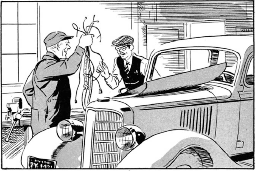
So many projects start by adding one or two things… extra 12 volt outlet here… maybe another light and then something else comes along that needs adding in. Before you know it you have a mess of spaghetti that the local Italian restaurant would be ashamed of. It is all too easy to fall into the trap of adding circuits to existing fuses…. or installing a new fuse and a few weeks later adding another circuit to it as it’s easier than installing another fuse.
Start with a plan…
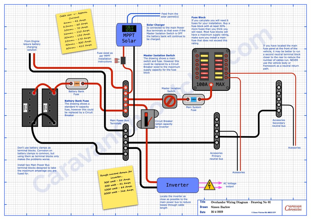
You can download these and other drawings from the Electrical Drawings page in the drop down menu under “Document Library”
You need to draw out how the major elements are going to connect together – leisure batteries, solar charger, DC to DC charger, inverter and include all the big fuses, buss bars and fuse box. Don’t think about where any of this goes for the moment just get the basic layout and how everything interconnects worked out. It might take a few goes but paper is usually cheaper and less frustrating than sorting out the mess afterwards.
Once you have all that figured out you can start working on the details… just how many fuses will be needed… and what ever number you come up with add half as many again as a minimum. Having a few spare fuse positions that maybe never used is way cheaper than in twelve months time having to install an additional fuse box. A this point you can start adding details…. what size cable is needed for each link, what sort of fuse box do you need.
You can also now start to think about specific facilities you might need. For example, many overlander vehicles will have a button on the dash that when pressed and held down activates a high current relay that links the house batteries to the engine cranking battery. Very handy to have… jump leads are not much use if you are 200Km from the nearest vehicle. If your only trip ‘off road’ however is the muddy car park at the local car boot sale than maybe not a priority.
Don’t use the vehicle chassis as a ground.
Modern vehicles are constructed using different materials and quite often panels and sub frames are glued together. Back when virtually all the panels were spot or seam welded steel, using the body and chassis as a ‘ground’…. which really isn’t a ground but the neutral return path… this was acceptable. However now, sections can be glued together and are often sub assemblies of aluminium and other light weight materials bonded together. Just because you see a neutral bonding point (earth terminal) don’t assume this is is capable of being a suitable point to bond the neutral side of a circuit or accessory you are installing. Modern vehicles often have small bonding straps between sections that can carry the current that the vehicle manufacturer rated the bonding point for. Adding additional equipment and accessories might exceed the original design spec.
I did see a spectacular failure due to a 3000W inverter having it’s neutral lead ‘grounded’ in the rear of a vehicle. Running at about 2000W the neutral side was trying to ‘return’ a current of about 170 amps through the body of the vehicle, which lead to serious damage to some of the vehicles wiring and a number of vehicle components… and a ‘repair’ bill of nearly £1500.Putting a riv-nut in a body panel that is mastic bonded to the body is not a suitable negative bonding point!
Additionally a number of vehicle circuits are now negative switching or operation and installing additional equipment or accessories could have unforeseen issues. Always from any accessory or piece of equipment you install, add the neutral return path back to a suitable single common point or buss bar you install for the purpose and connect this directly back to the leisure battery.
Ideally all the ancillary leisure circuits should never rely on any of the vehicle wiring and the negative side of the leisure wiring should only ever connect to the negative side of the leisure battery.
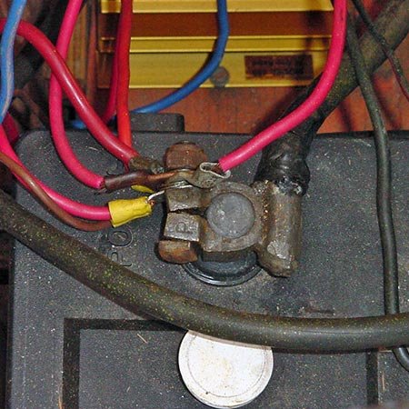
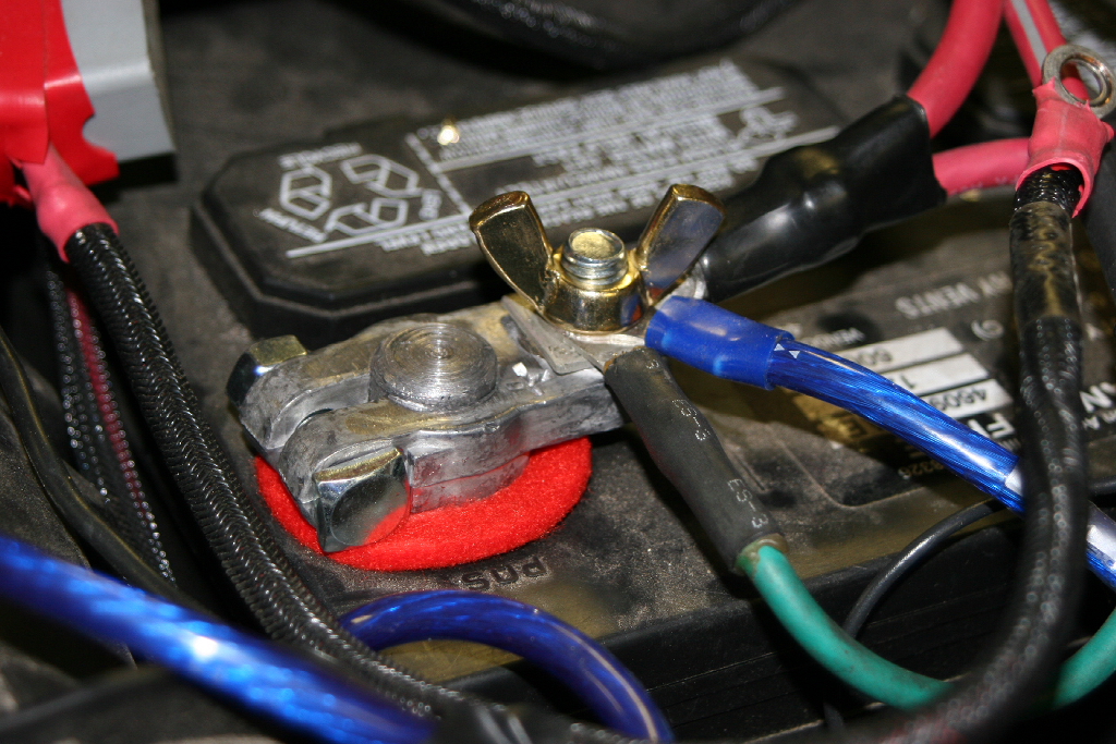
Don’t use battery terminals as a junction post.
Both the leisure battery and engine battery should only have connections that lead to either in the case of the positive terminal a master fuse /circuit breaker and isolator switch. The negative terminal should only have the connection to a master negative terminal point or buss bar.
Nope…..Not OK…. it’s a terminal not a junction post (image from the Internet)
If you want to install any sort of battery monitoring, it is convention to install the shunt on the negative return to the battery between the negative buss bar and the negative battery terminal. If you have multiple circuits terminated on the battery terminal it makes future changes and upgrades, including installing a battery monitor very difficult.
Just NO! (image from the Internet)
Using the battery terminals as connection points for multiple services also makes fault finding very difficult. Each circuit may or may not have it’s own fuse and it’s difficult to isolate circuits….. plus I’ve had enough sparks flying round when trying to disconnect a battery because someone did not install an isolator to know that it’s only a matter of time before one goes ‘pop’.
Just because it’s shiny…. NO!!! Not OK (image from the Internet)
Please, just don’t do it.
Have a think on this. If you had to go to an auto electrician to get a fault traced and corrected, they would immediately put at least an hours time on the invoice just to figure out what was going on with all the cables on the battery. Also, If you don’t have a battery master isolator installed, get one installed now. It’s a safety item that must not be missed out. Having the ability to quickly turn off all the leisure circuits in an emergency might just save you from the unthinkable happening.
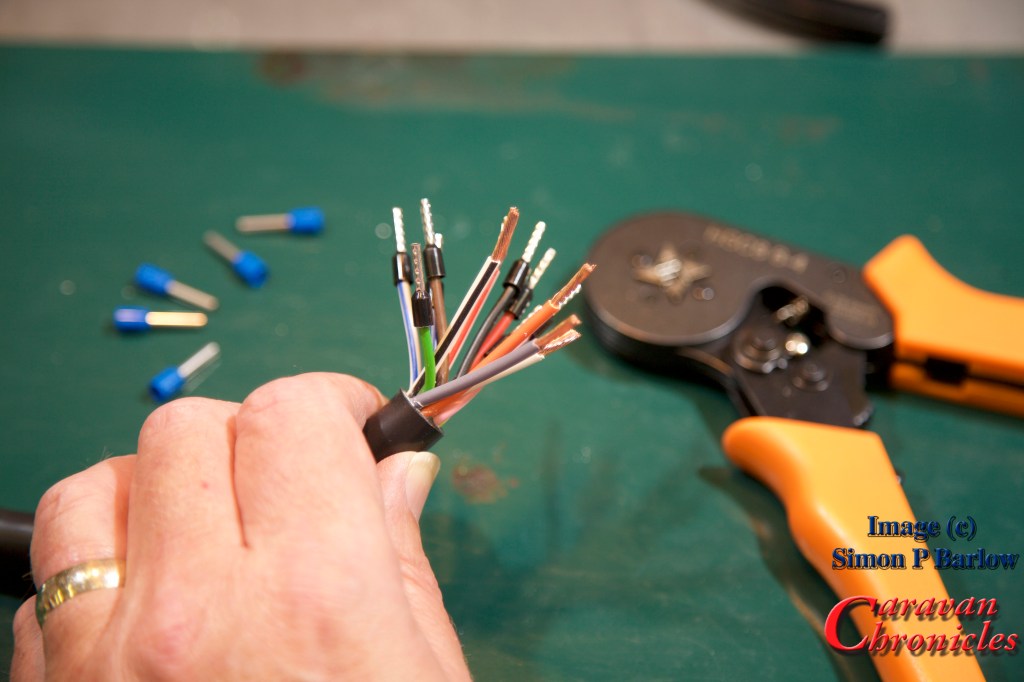
Cable Termination
Every cable should be terminated. Period. There shouldn’t be any cables in an installation that don’t have a crimped (or soldered) termination. Even if it’s a screw terminal such as those found in joining blocks or 13 pin plugs.
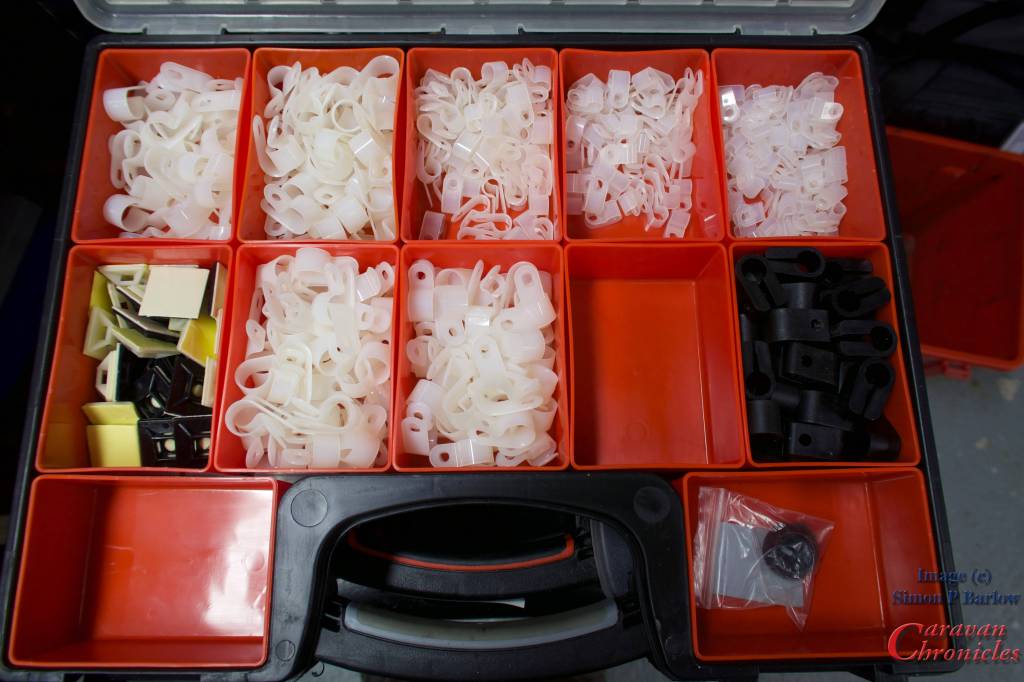
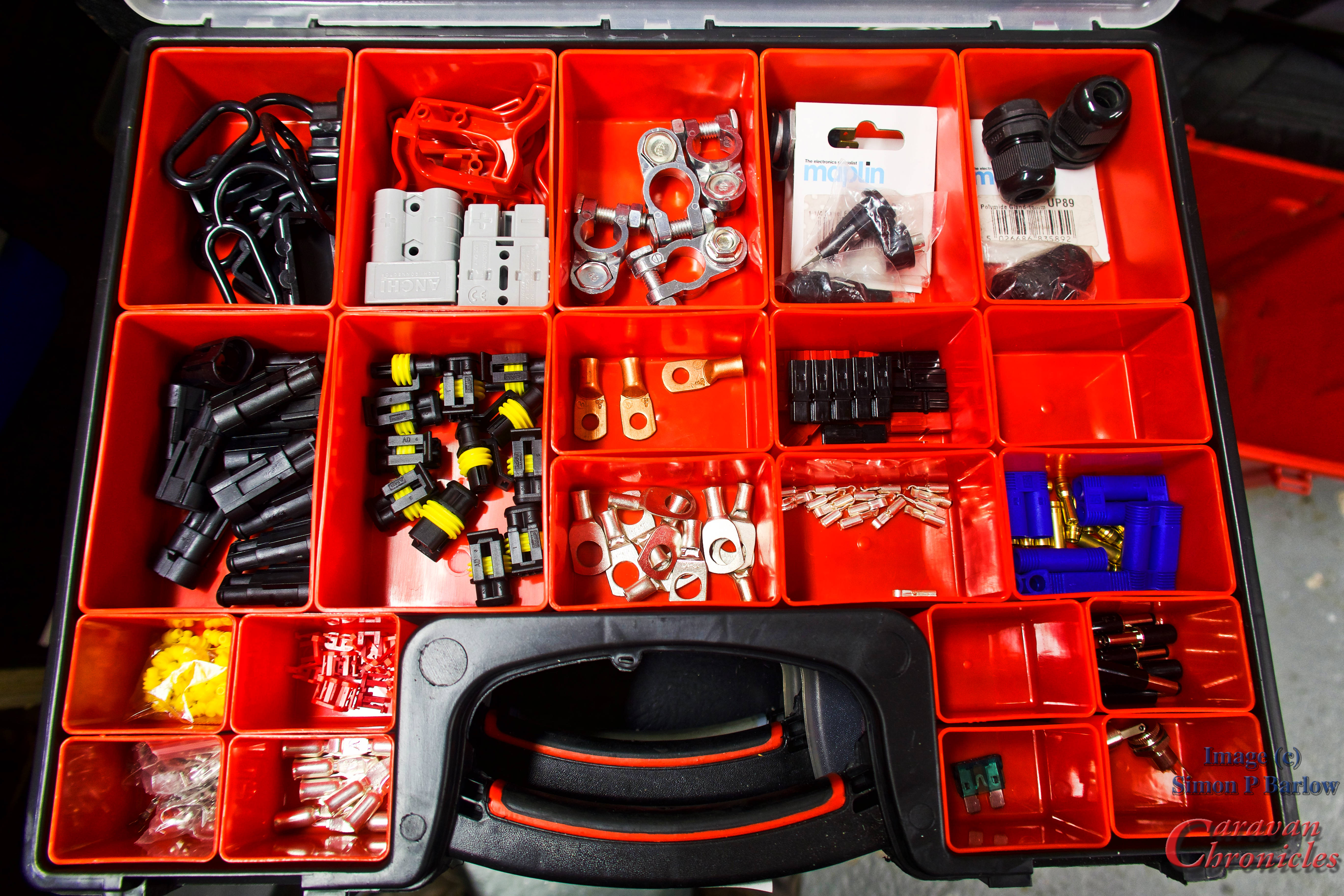
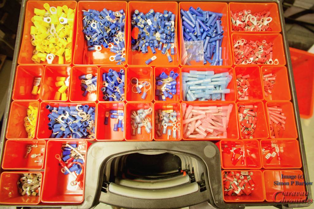
If you are embarking on a wiring project, its always best to start building up your stock of terminals. I usually buy selection boxes of terminals on line and supplement these with bags of single type connectors for the more commonly used ones. To keep everything organised tote organiser boxes are my preferred option.
A few of the 20+ of my storage boxes with wiring components
There is nothing more annoying than running out of the something and its always just as you want to finish a project off so you end up cutting corners.
For some of the larger cables, if you don’t feel up to making your own terminations there is usually a local auto electrician available that will terminate them for you for a small charge. However, a crimping tool that will terminate up to 50mm cable is not that expensive – around £27 and will probably work out cheaper in the long run. I’ve a link to the one I bought via Amazon and regularly use in the SHOP page.
Get the size right…
Selecting the right size or gauge of cable is critical. There are two factors that determine what gauge of cable to use for a installing any particular circuit. The maximum current that’s going to be drawn and the length of the cable. Once you have selected the right size cable then means you can select the right size fuse for the circuit. Never fuse a circuit greater than the current capacity of the cable.
Handy wall chart of cable size and terminal sizes.
You can download these and other drawings from the Electrical Drawings page in the drop down menu under “Document Library”
I generally tend to list what is going to be installed, then work out all the gauge for the cables for the circuits. From there it’s easy to see which is going to be the most popular gauge and rather than buy several different gauges of cable try to select a limited selection of gauges.
Always go for the safe option of over specifying the gauge of cable for any particular circuit. If it’s a 10 amp circuit and you have used cable suitable for a 16 amp circuit, it doesn’t mean however you need to use a fuse greater than the 10 Amp circuit requires.
Something else to consider too. Most 12 volt cables are copper, however if you are installing them in a less than ideal environment, such as a boat, you may want to opt for tinned copper cables. These are far less susceptible to cable corrosion. Even in the best marine installations I’ve seen copper cables corrode through in less than a couple of years.
Cardinal Sin! – Never ever use two smaller cables to make up the equivalent of one larger capacity cable. You would be surprised how many times I’ve seen this… sometimes done by “professional” tow-bar installers when reported poor leisure battery charing or poor fridge performance is reported and the voltage drop is too great.
Wiring Looms – wrapping it up properly!
Dressing cables into looms is not difficult nowadays. There are many options available on the market to help you produce a professional looking finished product. I personally like for looms within the vehicle using a felt finished looming tape. You don’t wrap it so it overlaps but at a sharp enough angle so as it spirals round the cable bunch it leaves some of the cables exposed.
Felt is good as not only does it keep the loom together, it allows quite a bit of flexibility and prevents cables from rubbing or banging on flat surfaces making a noise.
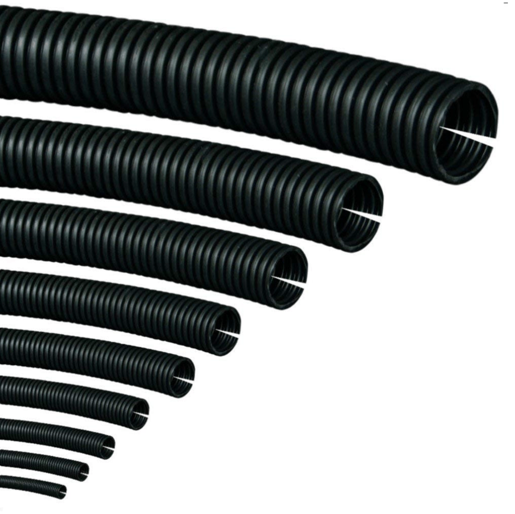
For any cables outside the vehicle body there are two options depending on use. In the main I’d go for split tube conduit. It’s available in various sizes and can be bought in either cut lengths or rolls. The other option is to use self amalgamating tape. It looks like ordinary PVC tape but as you wrap it round you stretch it and it releases a chemical which when overlapped onto its self becomes a permanent bond, effectively making a sealed tube. It is generally however fairly inflexible. Both have their place.
Anything in the engine bay or underneath the vehicle I use split tube and generally only resort to self amalgamating tape to seal inline joints.
Relays….. yes or no?
For me its Yes. I much prefer locating all the relays in one place therefore minimising the amount of heavy cable. By using relays to do the heavy switching you can use smaller and sometimes more attractive switches. I have in the past used 7 core trailer cable to connect 4 switches including LED indicators back to a relay bank rather than make up a custom wrapped loom.
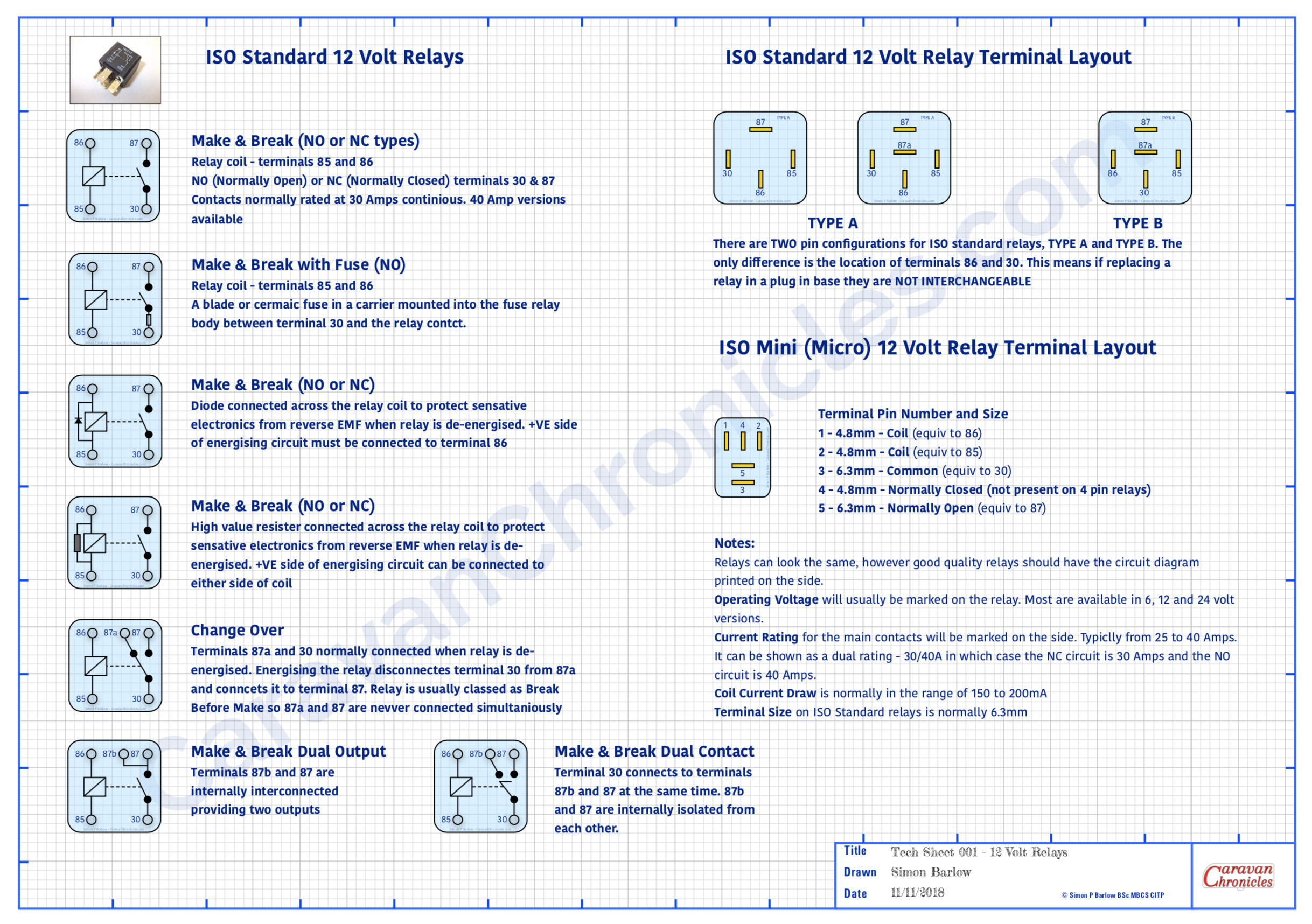
Handy wall chart of relay types
You can download these and other drawings from the Electrical Drawings page in the drop down menu under “Document Library”
It also makes tracing faults easier, as it’s simple to test if a switch is working, you can hear or sometimes feel the relay operating as you operate the switch. Its unusual to have a fault with a relay but quite simple to test… just unplug and swop over with a known working relay. If all the relays are located together it makes this task and testing the feed to the relays so much simpler. From that point all you need to check are the two wires going out to the device and the device itself.
Obviously some circuits don’t require a relay or if it’s designed to be turned on for a long period… such as a diesel heater, then adding a relay will just increase current draw, albeit small, on the leisure battery. A bit of common sense can easily determine if you should opt for a relay or not.
Grommet?…(no not Wallace’s friend!)
Whenever a cable or cables pass through anything solid you should use a grommet. You would be surprised at the amount of damage I’ve seen to cables due to either not installing a grommet to an insufficiently sized (too small usually) grommet.
When ever I pass either a cable or loom through a bulkhead for example I like to supplement a grommet with a bit of heat shrink sleeving over the cable as well. Even passing a cable through an existing grommet from the engine compartment to the interior, adding a length of heat shrink sleeve won’t do any harm.
There’s a link to these in the SHOP… only about £7 for the full box.
Having a handy selection of grommets available before you start threading wires through is far better than trying to install protection afterwards. You’d also be surprised at how many cables I come across that have been damaged while pulling through holes in metal and wood panels. Always better to start with a grommet or two! Where a cable or loom passes through a grommet, it’s aways best practice to try and anchor the cable or loom either side of the grommet to something solid using “P” clips. This will reduce the chances of ‘fretting’ with the movement of the vehicle.
While we are on grommets…. a quick note about cable-ties (zip-ties). Stop doing them up so tight! I’ve come across cables cable-tied to a chassis rail so tight that the cable-tie has cut into the insulation and is fretting the conductor inside. Cable-ties are generally made out of a harder plastic than the cable insulation so will over time wear away at the insulation.
Get yourself a cable-tie tool that not only allows you to precisely control how much tension you put on the tie but also cut the end off so that there isn’t a wrist slashing booby trap lying in wait for some unsuspecting person. I use a fairly cheap pair (left). I think they were around £8. So not really expensive. But they make a nice neat job of installing multiple cable ties with the correct tension and the ends cut cleanly off level with the lock tab. You can buy ones that have a tension dial built in so you can set them to a pre-tension, but I find after a bit you know just how much to squeeze the handles to get the correct tension.
So what is the correct tension… well if you are doing them up so tight an elephant could dangle on the cables then that is too tight. They should be tight enough so as not to slip but you should be able to spin them round the cable(s).
Cable-ties really should not be used to make looms or anchor cables or looms to anything solid. If you want to make a loom, wrap it in specialist loom tape. If you want to anchor cable or a loom to something solid use a “P” clip. If required… use a length of heat shrink to make the loom a tighter fit in the ‘P’ clip.
I know you are dying to ask…. when do I use cable-ties? Well generally at the installation stage to get things to stay in place before installing P clips or if I have to run a new loom along the same path as an existing loom, I generally opt for cable-ties to hold them both together (as long as the original is suitably anchored to support both)
While we are talking abut cable-ties… I have seen the worst kind of mistakes in the use of them. It is not OK to cable-tie anything to brake lines, fuel lines, vacuum lines, hydraulic hoses, coolant hoses or steering components (yep one bright spark cable-tied his front LED light bar wires to some of the steering components!)
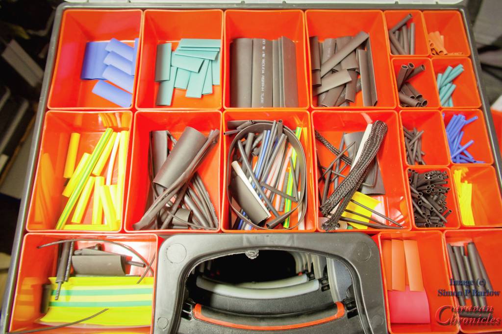
Heat Shrink Tubing
An absolute must have in my opinion. There are two main types – plain and pre glued. The plain are the main one you would use, while the pre glued are great if you have to over sleeve a connection to make it waterproof. As you heat up the pre-glued type, the glue softens as the tube strings and bonds to the cable as everything cools. They can be a little more rigid when installed, so make a service loop in the cable. The finished covering is usually waterproof enough for brief submersion if done correctly.
Having a selection of sizes and colours is handy and assortment boxes of multiple sizes and colours can be bought on line cheaply enough. In the workshop I use an old paint stripper heat gun on low power as I find that is more controllable than a flame.
Bridging the gap… something in the future?
Although not so common in the UK, in Australia and the USA wild camping (boon docking) is probably as popular as campsites. To this end trailers and caravans usually have much larger battery capacities than anything found in Europe. It’s not uncommon to find outfits with 600 to 800Ah battery banks recharged mainly be solar, buy increasingly (especially in Australia) an additional bridge between tow vehicle and trailer is made using heavy duty “Anderson” connectors and cables capable of supplying upwards of 60 Amps from the vehicle to the leisure battery bank.
With the cost of lithium batteries reducing almost daily, I can foresee very soon that light weight lithium batteries will be installed in caravans. The down side of this currently and trying to retrofit Lithium is the existing charging setup of current European vans is not really suitable for looking after these type of batteries. We have a Sterling Power Wildside unit installed in our caravan which allows us to charge any type of battery chemistry, including lithium when connected to the tow vehicle. The draw back is the caravan’s inbuilt charger is only capable of wet lead acid or AGM. I think that a high capacity DC to DC charger installed in the vehicle and an additional cable to supply the caravans battery banks may not be too far away. It’s something you might want to keep in mind for the future. It’s something I’m looking into currently.
Well, that’s a bit longer than I anticipated and there is still a few things to cover. If you made it this far…. take a toffee out of the jar… well done! If you think I missed something or would like me to cover something specific, drop me a comment below.
The problem with information on the internet is that although there is some great advice to be found there is also some less than great…. poor… really really poor advice and sorting out the good from the bad is sometimes not easy.
We are currently pitched on the Caravan & Motorhome club site Beechwood Grange near York and I decided to sit down and pen this post as for the last few months I seem to have been sorting out a number of problems via emails and phone conversations that really should not have arisen.
I’m going to give you a couple of examples of what’s been dropping in my inbox. To protect the inoccent I’m not going to name anyone or the channels. I do have the OK to relate these issues.
Case 1
“Hope you can help, I’m converting a VW Transporter into a camper van and have been following a number of YouTube channels for information on how to do it. It’s nearly complete but I have a problem when I go to use my inverter off grid. The base of the seat starts to warm up and a get a funny smell in the front of the van”
After an exchange of emails and a few photos were sent I eventually worked out what was going on. The 2000W Pure Sine Wave inverter was floor mounted in a cupboard towards the rear of the van where it was convenient for the mains sockets on the inverter to be reached. A suitable size Positive (+ve) lead ran back to the two 100Ah AGM batteries located under the front seat. A suitably sized Negative (-ve) lead also ran back to the batteries and was bolted to the chassis under the seat along with a number of other smaller -ve leads. The batteries were mounted on a wooden platform above this connection. The +ve lead from the inverter went to one battery +ve terminal and a link wire to the second battery +ve tied the two together. The size and rating of this tie wire was a lot less than it should have been.
The -ve posts of each battery had a very short 10mm2 cable going to a threaded stud mounted on the base of the seat and were helpful on to the stud by a star washer and nut. The seat base was a 3rd party metal fabrication hat had been powder coated and bolted to the vehicle floor by 4 bolts and ‘penny’ washers.
What was going on?
When the inverter was operated, it drew current from the battery down the +ve lead. Apart from the fact there wasn’t a fuse between the battery and inverter this side of the circuit was OK. The return path however was a different story. The inverter -ve lead was connected to the vehicle chassis under the seat – not at one of the seat mounting points. The -ve of the two batteries was connected to a stud that was a press fit into the seat base. It didn’t have a hexagonal head just a mushroom head. It was also way under size for the terminals that were fastened to it. The oversize star washer stopped the nut pulling through the terminals. The return current path therefore had to flow into the vehicle chassis, up the four bolts holding the seat to the floor and through the seat base to the push fit stud and finally into the two short leads connecting the battery -ve terminals. The relative high current drawn by the inverter through the single undersized push fit stud and the four floor bolts that were securing a powder coated frame with penny washers presented enough resistance for 60 or 70 Amps of current to start to heat things up a bit and burning off some of the powder coating. 70 Amps passing through a 0.1 ohm resistance will generate 490 watts of heat (calculated using R x I2 = P) this is why it’s critical to get any cabling correctly crimped with the right terminals for the job.
Conclusion
Don’t rely on the vehicle chassis as a return path. install cables for both ‘legs’ of the circuit from source to destination and back again.
There wasn’t a fuse installed near the battery. Any cable coming from a battery MUST have a fuse close to the battery before it goes off anywhere to supply anything else.
If a cable terminal requires an M4 nut and bolt…. use an M4 bolt nothing smaller will do.
If you are ‘grounding’ to anything metal, clean the surface, use a dab of protective dielectric grease (there are different ones for steel and aluminium!) and make sure any washers used work correctly. Flat clean washers for electrical contact and a star washer as a mechanical anti vibration measure to stop the nut loosening.
Case 2
“When ever we have been away for a few days off grid on the return trip there always seems to be a strange smell coming from the engine compartment. We have a self converted T6 camper and 400Ah of AGM leisure batteries with 240 watts of solar on the roof. After watching a couple of YouTube installations of DC to DC chargers I recently installed a Redarc DC to DC charger to help keep the leisure batteries in good condition and fix some issues I was having with the smart alternator”.
OK again after several email exchanges and a couple of video clips I got to the bottom of this one as well. The RedArc unit is capable of charing at 50 Amps and to do this pulls around 55 to 60 amps from the vehicles alternator. However there are a couple of issues in doing this. One of the first things that the Car Audio guys always recommend before installing any of the mahoosive bass pumping amps in vehicles is to replace and upgrade three essential cables. The first is the cable from the alternator output to the battery, the second which might not seem so obvious is the ‘earth strap’ as it is sometimes called from the engine to the vehicle chassis. This need either replacing completely with a larger cross section and also where it terminates on the vehicle needs altering. Usually the Audio boys install a new cable from the alternator mounting bolt directly back to the negative battery terminal*. Why” Well quite often the engine earth strap is just a simple copper braid strip sized just big enough so the starter motor current won’t burn it out for the 5 to 10 sends the starter is operated. You start trying to push the engine battery charing current and the additional 60 amps for the DC to DC charger through it, it starts to get warm. Not a problem as usually it’s not covered in a PVC jacket and hanging down in a bit of air flow under the engine. So the Audio guys change or upgrade it and they pull more current than we do. The third and last one that is upgraded is the short stubby battery negative lead going to the vehicle chassis. For our purposes, not really a necessity but hey ho.
*A note of caution. On most vehicles now there is a shunt between the large negative cable going to the battery and the negative terminal of the battery. This allows the vehicle ECU to determine the current flow in and out of the battery. It is important that you only connect any ancillary equipment to the cable side of this shunt and not to the battery side.However some DC to DC chargers specify you connect to the battery side of the shunt. Please refer back to the instructions with your particular unit.
What was going on?
Well basically the negative side of the circuit was getting a bit warm and the lead from the alternator was running at virtually it’s maximum rating. What you have to remember is that the vehicles electrical system is really designed down to a price and to do just the job of keeping the vehicle running. As soon as you start to ask a bit more of it you are stressing some elements and you have to consider all aspects and upgrade parts sometimes.
Conclusion
Adding an additional earth strap from the alternator mount directly to the chassis side of the shunt on the negative post of the engine battery and upgrading the alternator positive cable made a big difference and there is no longer any smell after a couple of hours of charging from the engine. Apparently starting the diesel engine has been improved with the report: “it seems to turn over a lot faster when starting” so maybe there was an underlying issue with engine earthing somewhere?
My two cent’s….
Don’t use the vehicle chassis as a neutral return path for any additional equipment you install. Modern vehicles are not so much welded as bonded together and some have aluminium or plastic body panels. Additionally even the steel they are made from is not as good a conductor of electricity as copper. Leave the vehicle electrics to the vehicle body and install your own neutrals.
Don’t ‘ground’ the leisure battery to the vehicle body. Keep the leisure battery circuits isolated from the vehicle body. Run a suitably sized neutral cable directly from the leisure battery to the vehicle battery.
Don’t use leisure battery terminals as a place to connect everything. Use a proper terminal bus bar block for live and neutral connections. The only connection on your battery terminal should be the main conductor going to either a second battery or a bus bar terminal block. The only exception to this is for battery monitors!
Don’t assume the vehicle electrics are up to the job. Most vehicle electrics do the job they were designed to do and not much more. As soon as you start asking the alternator to charge another one or two 100Ah batteries you are ‘stressing the system’ to a greater or lesser extent. Some big 4 x 4’s can handle this, some smaller vans might not be able to. Consider what you are installing and think about how the vehicle will handle this and look to see if anything needs upgrading.
Know what cable terminations to use and where. Also don’t cheap out on the correct terminal installation tool. If you are building or converting a camper van is it worth saving £25 on a proper ratchet crimp tool?
Don’t watch someone on YouTube do something and assume that if you do it exactly the same way it’s going to be right. It’s interesting on how many times people make a video on wiring or installing equipment and follow it up with “if you want to know more go and watch so and so’s video about it. He produces really good videos how to do this” Just because someone produces really good videos doesn’t mean the videos show how to do something correctly. It’s only how they did it, not an installation bible. You have to do your own research and learn to sort out the good guides from the bad.
I have watched an awful lot of YouTube motorhome refits, camper van, step van and bus conversions etc and a lot of the electrical installation – especially on the 12 volt side is poor in my opinion. I’m not an expert however and I’ll only ever say how I’d so something and the rational behind why I’d do it that way.
Just throwing this out there to see if there is any interest….. I was thinking about doing either a small forum on the blog or a Q & A page as a resource for some of the electrical ramblings. Would that be of interest/use to anyone? I do know that quite a few of the electrical drawings I have done have been downloaded and again wondered if specific drawings for equipment would be useful. Let me know in the comments below.
Ok, not one of my usual blog posts. I get a lot of email asking about various electrical items related to caravans and motorhomes and a few things seem to keep cropping up on a regular basis. One is to do with 12 volt relays… what types are there and what are the pin connections.
Another is to do with cable size relating to load and its relation to the length of cable…. “I have a 40 Amp load and its 3 metres from the battery… what size cable do I need?” type questions.
In the past I’ve emailed back with answers, but one caravan engineer asked me if I know of any information sheets that had this type of info that he could put above his workbench.
So I’ve produced a couple of A3 size PDF information sheets (they will print A4) that can be downloaded printed out and pinned up, shoved in your notebook, glued to the lid of your tool box or used to wrap that must have tool present for your beloved caravan or motorhome DIY enthusiast in your life (seasonal eh!)
(I have been told that Office World can print and laminate A3 PDF’s cheaply…. I never knew that!)
I have stylised them as technical drawings and I’ve had to watermark them and some of the icons as I found a lot of my drawings were ending up “as is” or edited on various sites and forums without any credit or link back to Caravan Chronicles. You are free to print out and use them for your own personal use, but if you wish to use them (or any of my drawings) for commercial use, inclusion in blog posts or forums please include a credit line back to CaravanChronicles.com and drop me a line to let me know.
We are just back from Chester Fairoaks after doing the Chester Christmas market and a bit of shopping at Cheshire Oaks Designer Outlet Village and will be adding off to York for a bit more Christmas Market action.
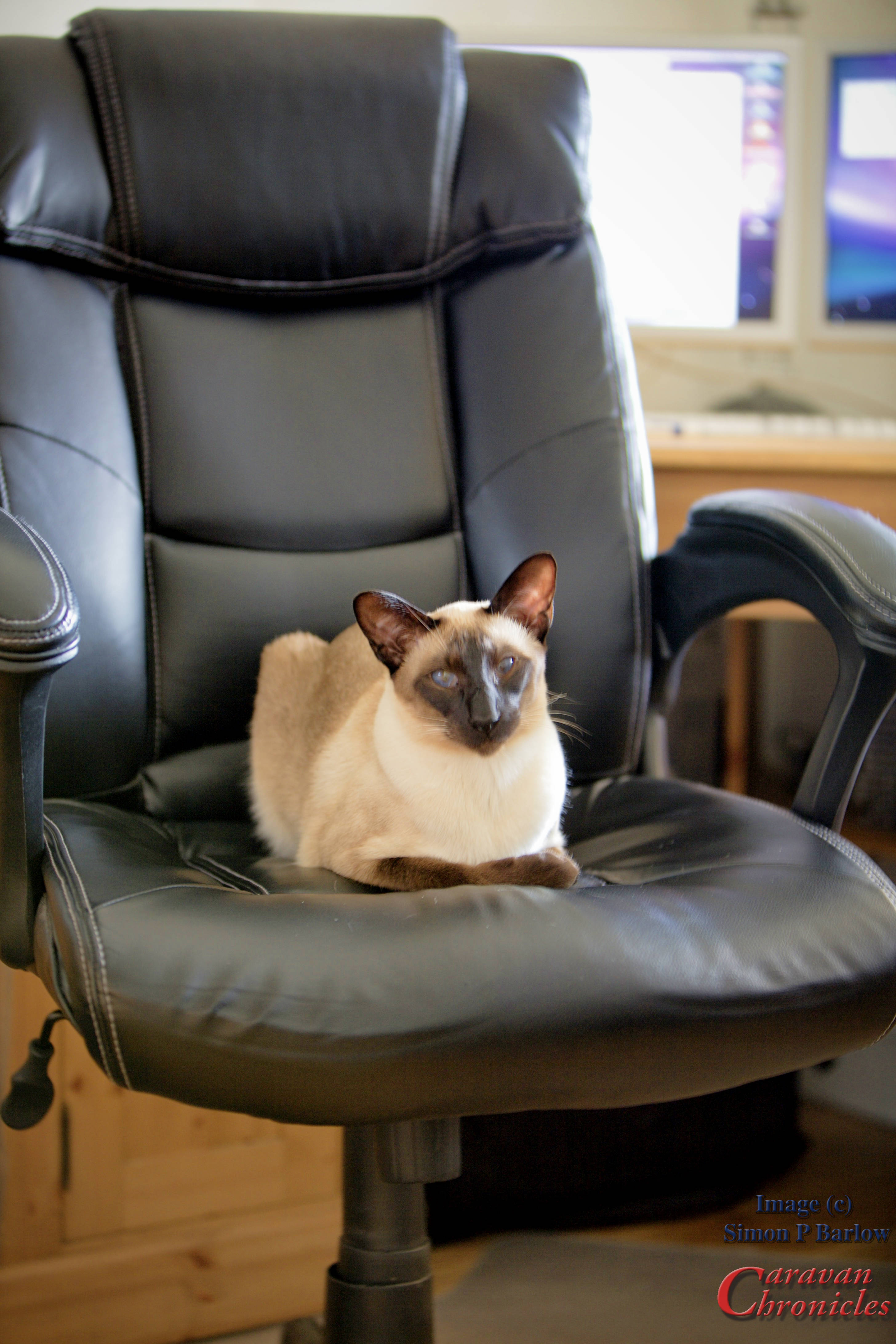
I have a couple of more information ‘posters’ in development but if you have any ideas for future offerings, drop a line in the comments below. Of course my legal advisor – Henry has asked me to point out E & OE
(Everything on the internet is improved by a cat apparently… so here’s Henry)
The North’s largest outdoor leisure show for campers, caravan and motorhome owners, will be pitching up at Manchester’s EventCity from 18th – 21st January 2018 offering a huge range of inspiring ideas for lovers of the great outdoors.
This is our “local” show and hopefully it will continue its record each year of increasing the attendance figures over the previous year. With leading manufacturers and dealers in attendance, a range of celebrity speakers, including television presenter Matt Allwright and The Camping and Caravanning Club President Julia Bradbury.
Rob Debenham, Show Manager, says: “We’re hoping to build on the success of last year which saw 36,102 visitors attend over four days and we are really excited about the 2018 show. With some exciting new attractions in store for our guests I’m confident we’re on track to deliver our best show yet. It offers something for everyone, and with kids under 16 going free, it’s a great value day out for the whole family and of course the perfect chance to find your ideal caravan or motorhome.”
With over 200 exhibitors, visitors are sure to leave feeling inspired at the four-day event to start planning the trip of a lifetime.
Tickets to the show also include a free show guide and free entry into the co-located Destinations: The Holiday & Travel Show with live cookery demonstrations on the Food & Travel stage. Featuring hundreds of travel companies such as Trailfinders, VIA Rail Canada, and Great Rail Journeys, as well as tourist boards including Morocco, Cuba, Malta, Massachusetts, Barbados and more, visitors are sure to find something to suit all travel interests.
The box office is now open and tickets are available at www.caravanshows.com or by calling 0844 873 7349 or of course you can buy on the day in the foyer.
We will be there on Thursday for the opening, so hope to see you there!
I have been receiving a lot of emails over the last two or three months from people reporting issues around charging their leisure batteries after changing tow vehicles and a similar number from people who are having problems with performance of the installation of the electrical harness on their new vehicle tow bar.
I’ve spent quite a bit of time answering emails and thought I’d try to sum up what is happening. A lot of this is also going to apply to Motor Homes, especially if they have a new Euro 6 engine. Continue reading →
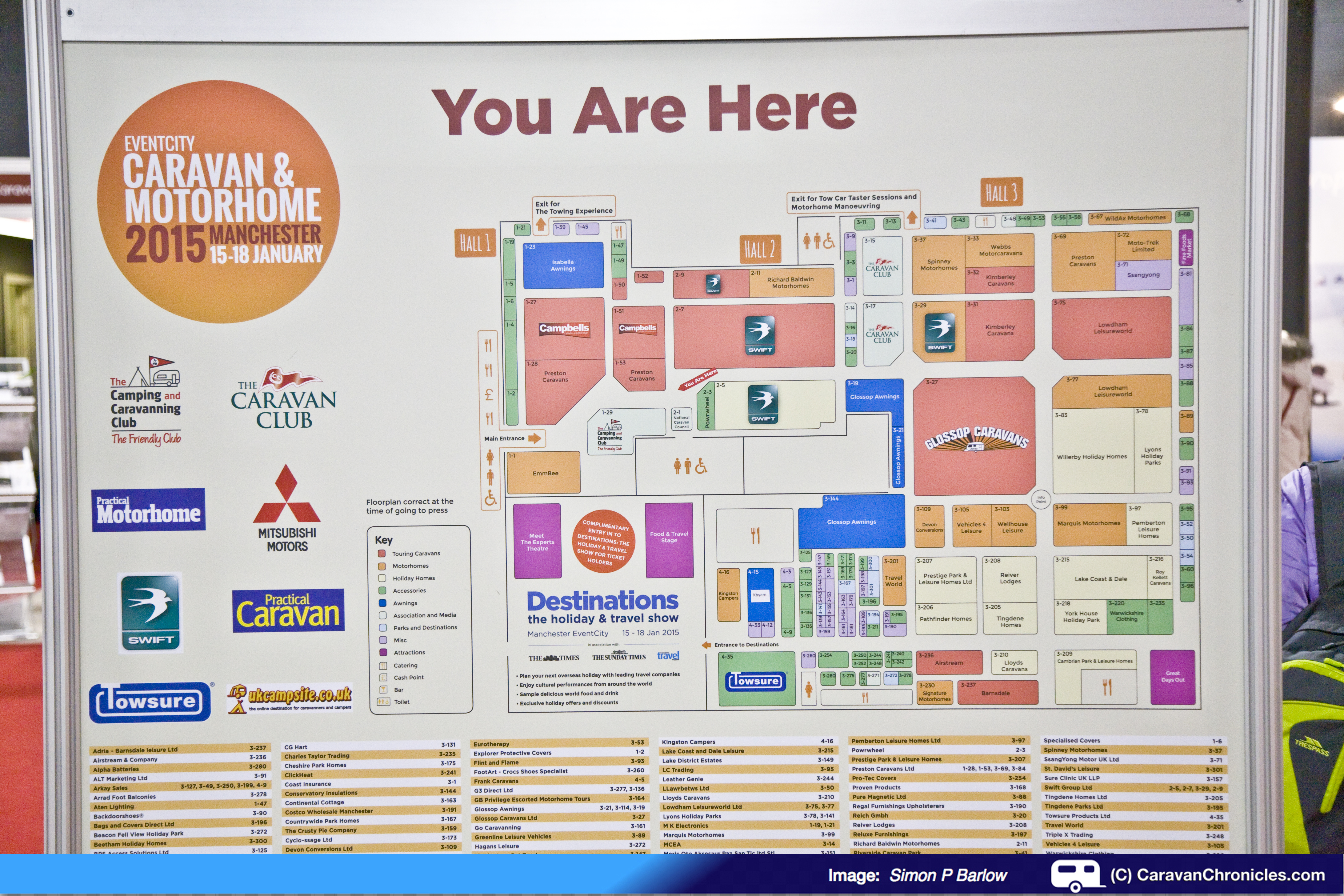
THE CARAVAN & MOTORHOME SHOW, MANCHESTER 15th – 18th January 2015 EventCity, Phoenix Way, Barton Dock Rd, Manchester M41
Show Opening Times:
Thursday: 10 – 6pm
Friday: 10 – 8pm (free for visitors from 5pm onwards)
Saturday: 9.30 – 6pm
Sunday: 9.30 – 5.30pm
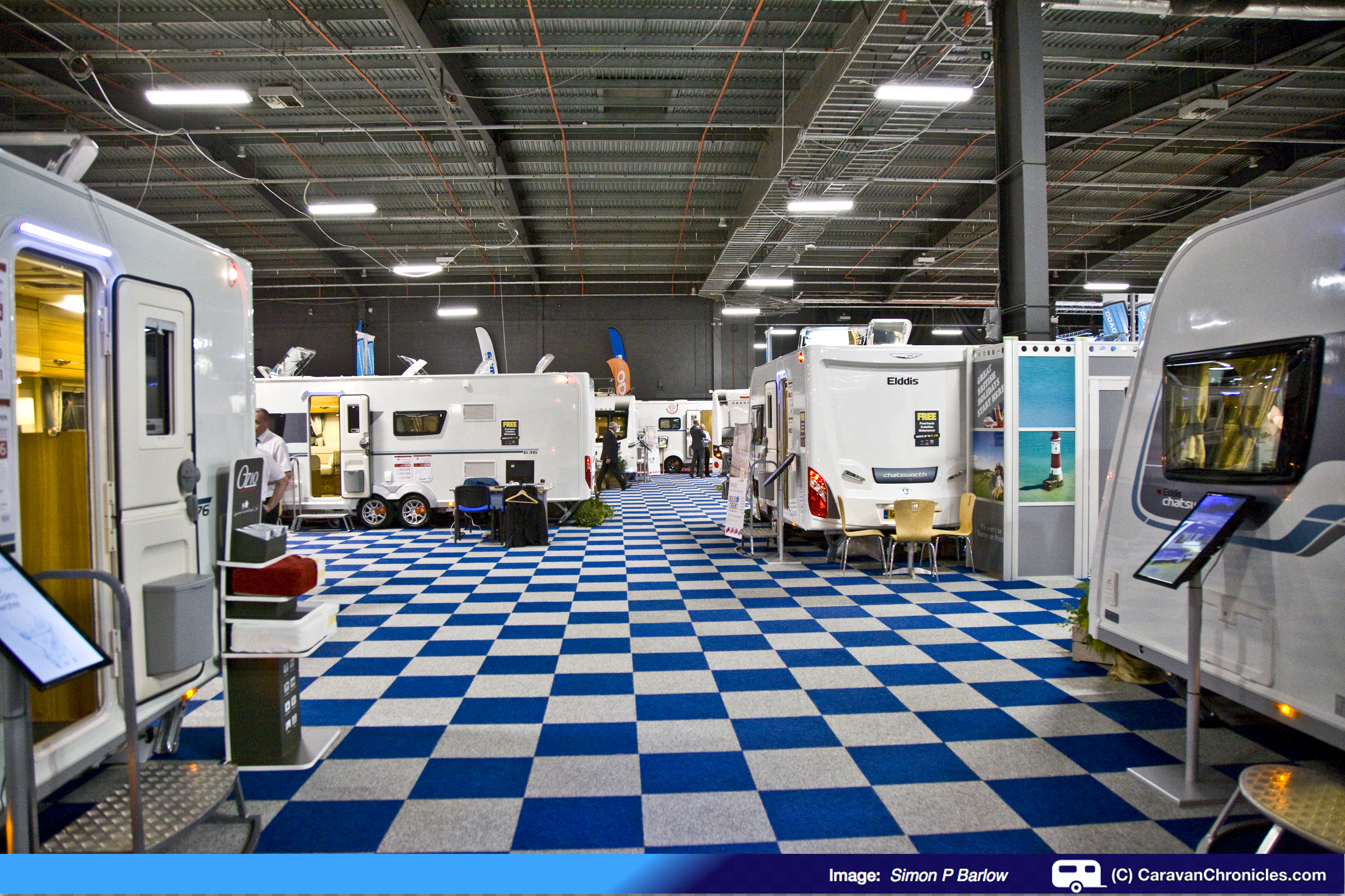
The 2015 Caravan and Motorhome show was held once again at Event City near the Trafford Centre shopping mall. Although in its 17th year, this is the fourth year its been held at Event City and 2014 saw a record-breaking attendance of over 27,900 visitors, up by 13% on 2012. if the success continues at the current rate it won’t be long before it might have to go from a 4 day event to a 5 day event.
Although the weather was forecast to be a bit wild and windy, the sun was shining and the M60 motorway was surprisingly quiet as we left home this morning and it only took about 20 minutes to get there. Car parking is not a problem and this year they have introduced a temporary traffic light crossing on Barton Dock road to make it easier crossing from the car park to Event City.
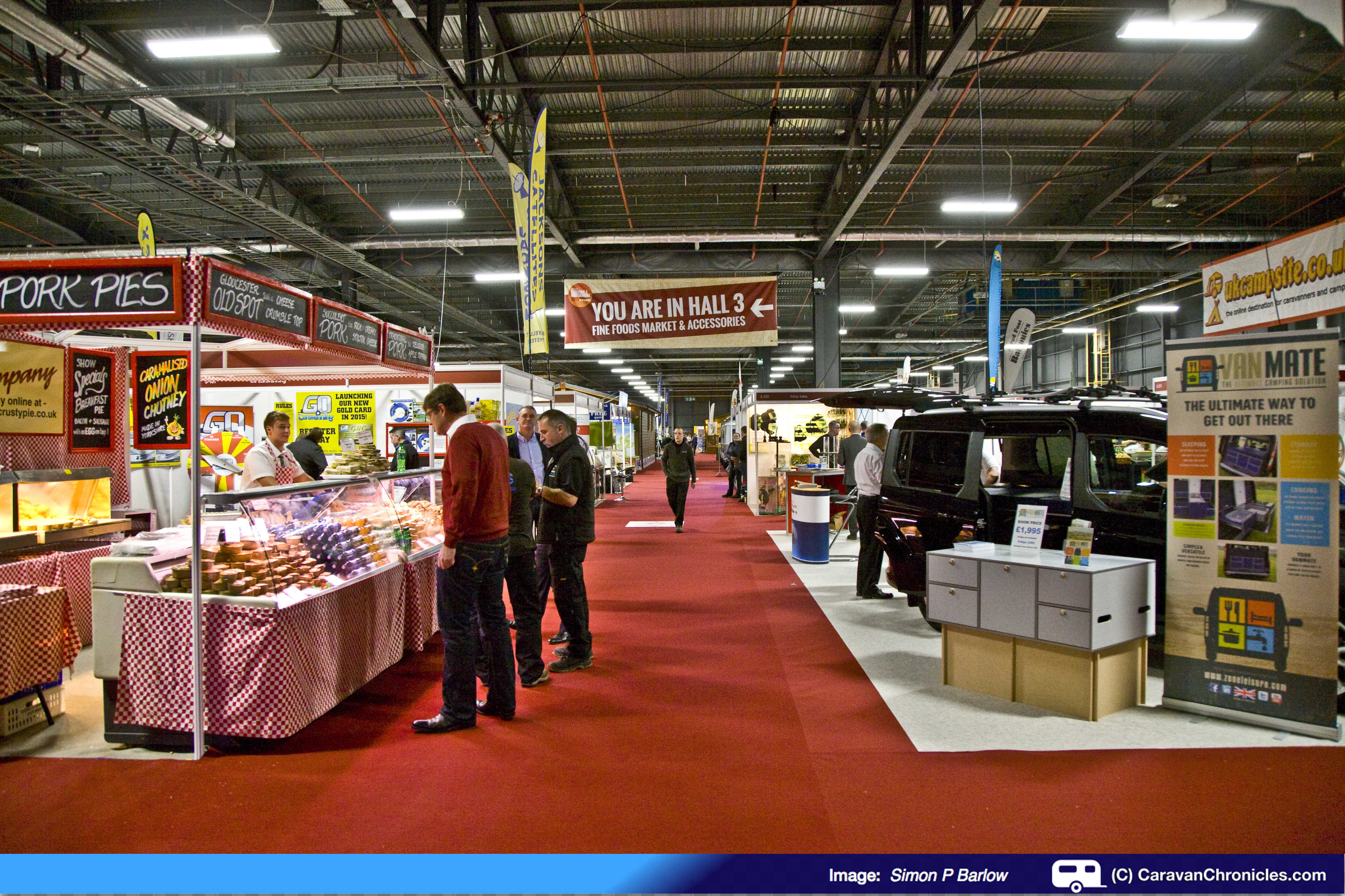
The quiet before the storm… before the show opened!
Thankfully we had a chance to gain access before the show opened to the public which gave us chance to check out some of the stands before they got too busy.
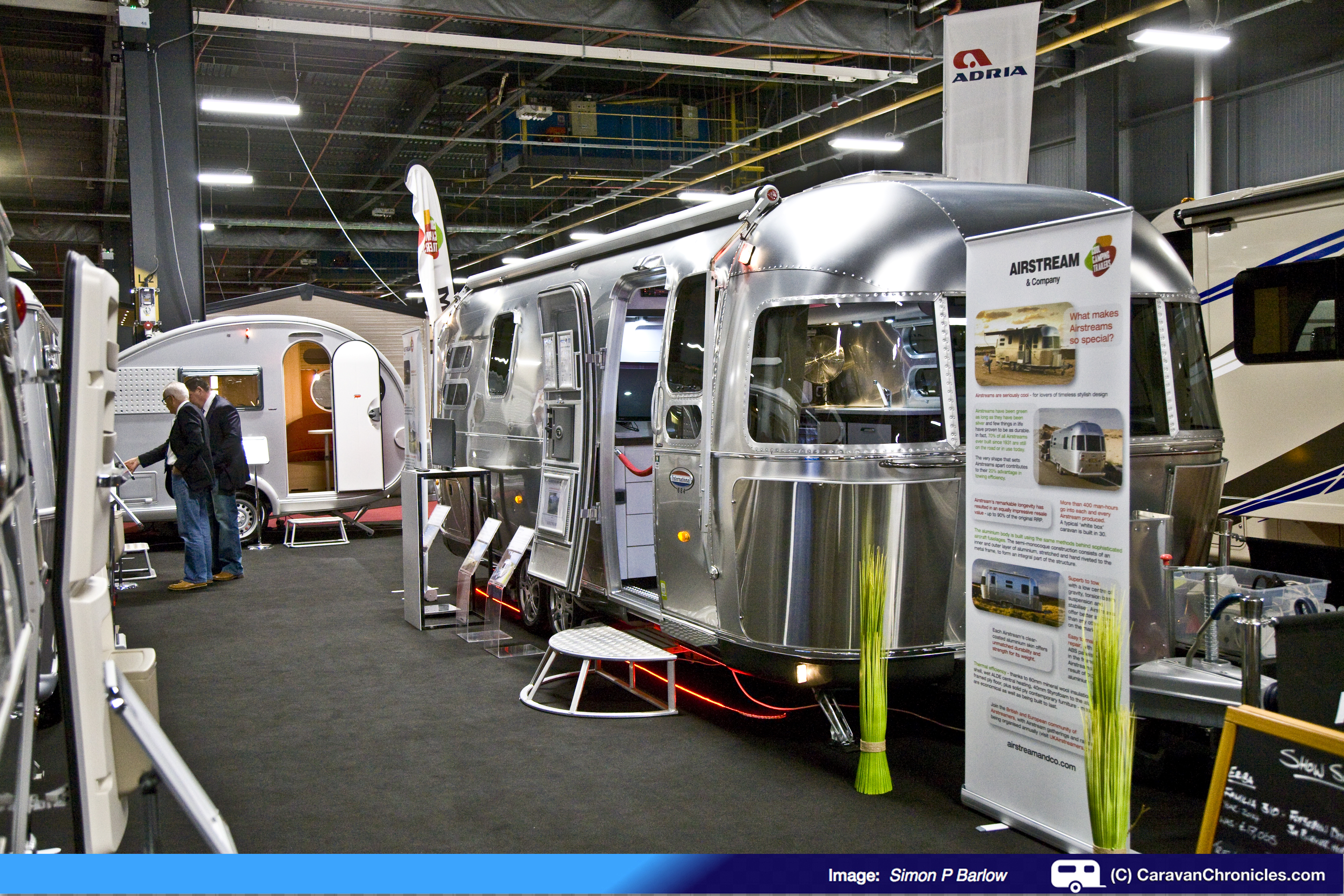
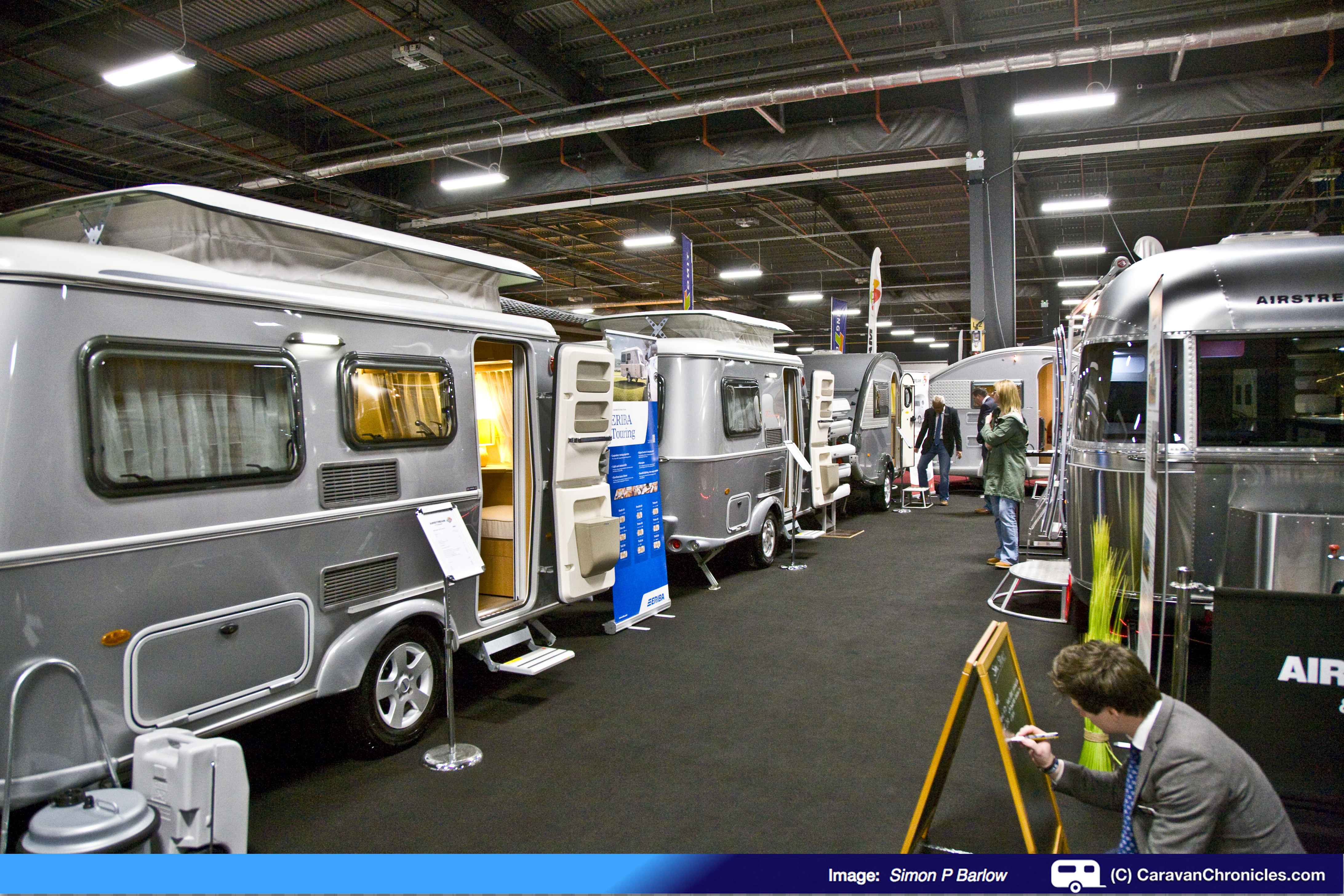
One of the new exhibitors to the Manchester show this year was Airstream and they had one of their iconic Airstream travel trailers along with TAB and the largest gathering of Eriba caravans we had seen.
Although you do see a lot of Eriba caravans on sites, it’s not often you can get to look round and for such a tiny caravan on the outside, really there is a bit of a space time thing going on as I’m sure they are bigger on the inside!
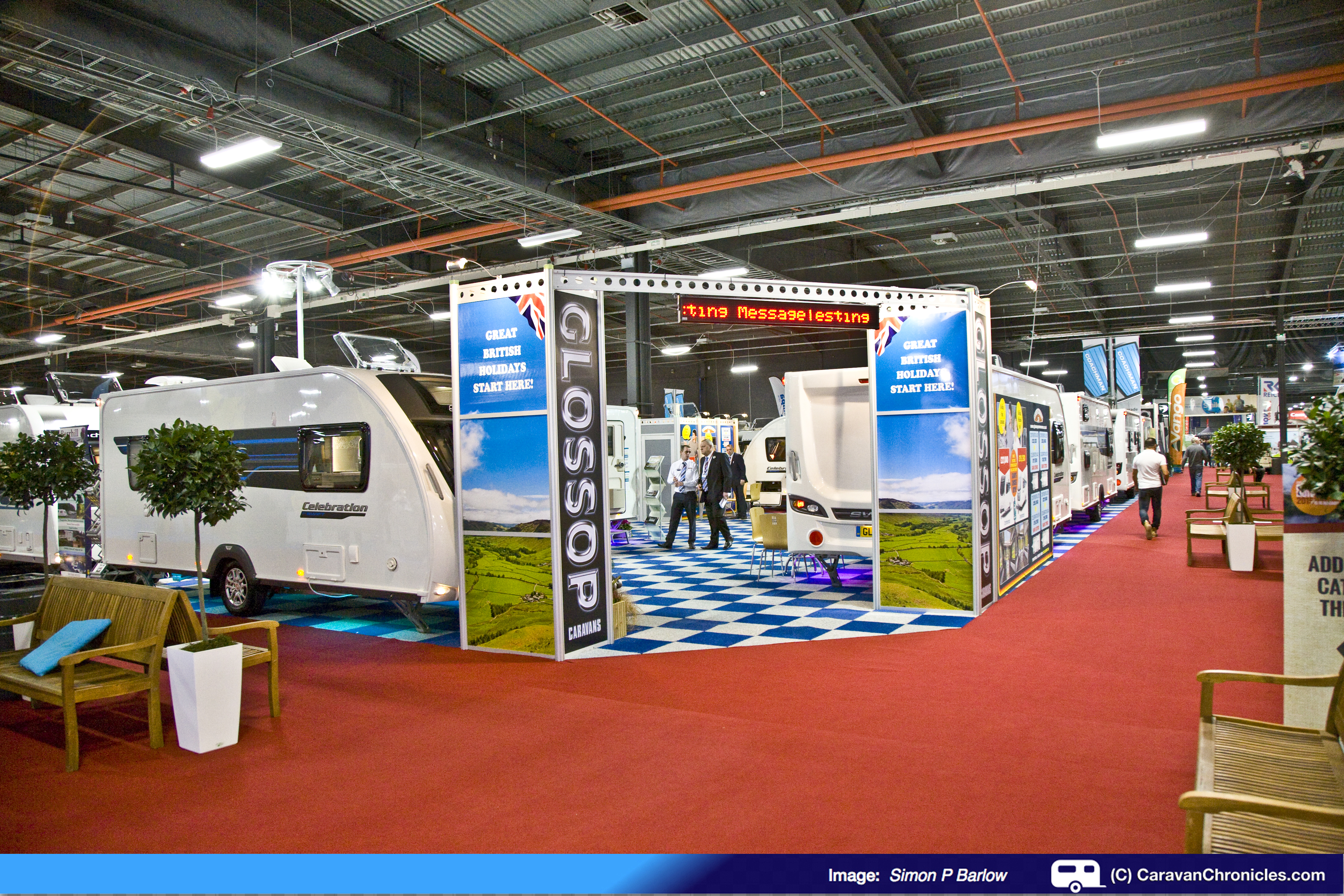
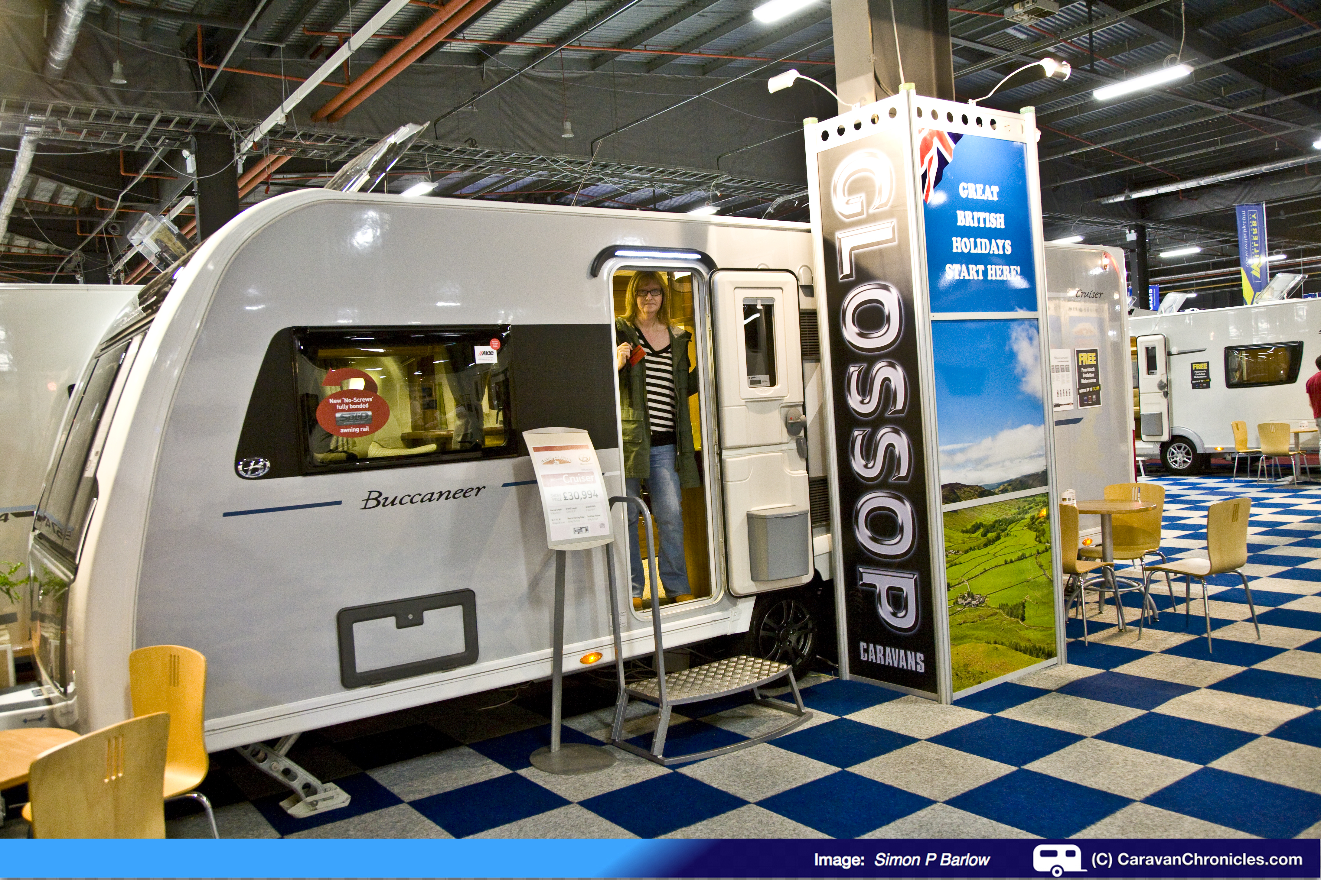
I think the award for most caravans on a stand has to go to Glossop Caravans for their mahoosive stand…
… it needs a map all of its own!
Glossop Caravans are one of the biggest caravan and motorhome retailers in the country and this show is almost in their back yard and they make the effort to make sure that they cover as many of the models as possible.
Sue’s favourite caravan of the show… I thought I was going to have to go and do a deal with Brian Lang before she would come out!
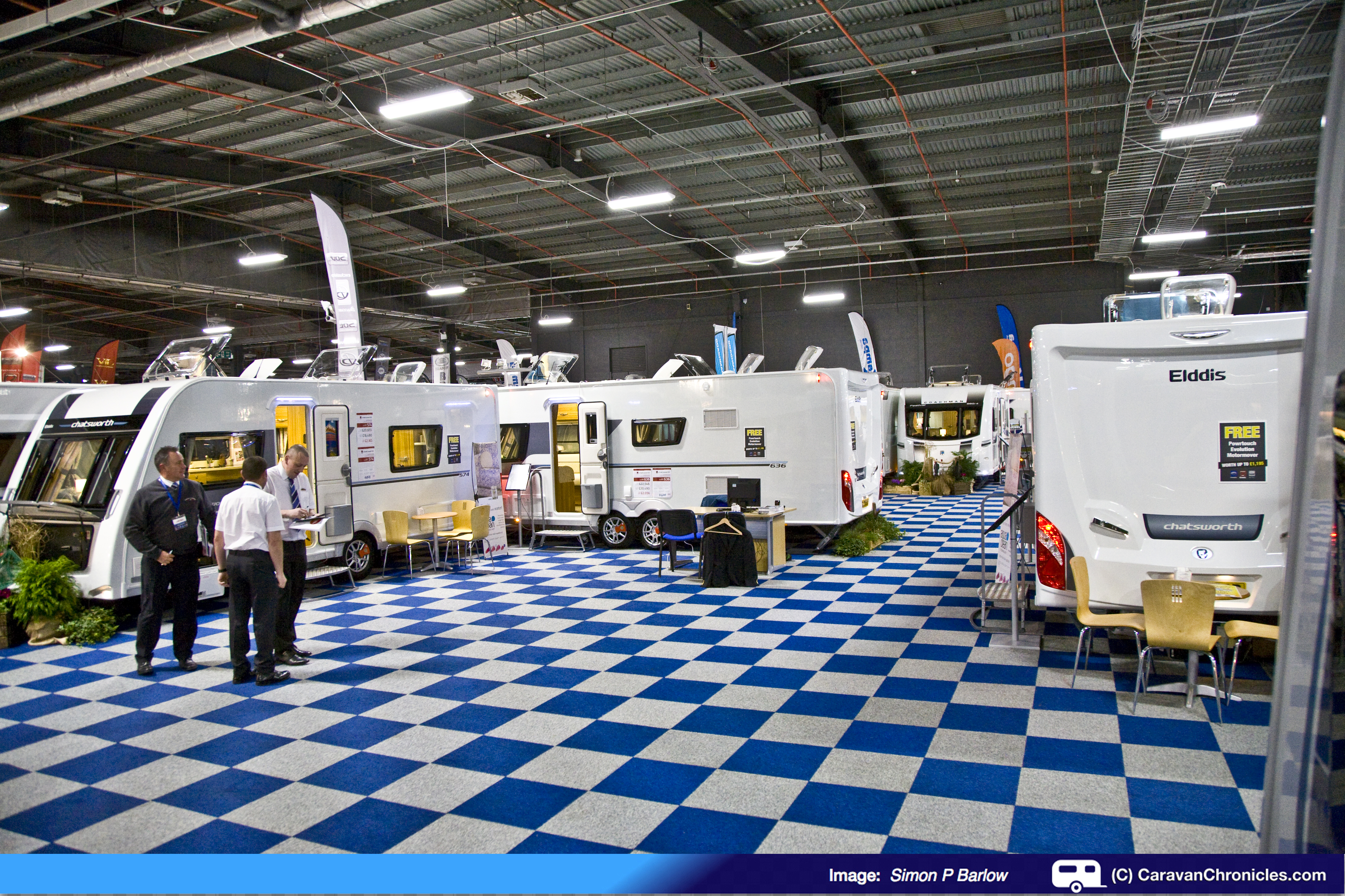
Between Glossop’s stand and Swift’s stand I think every option for Swift Group products was covered.
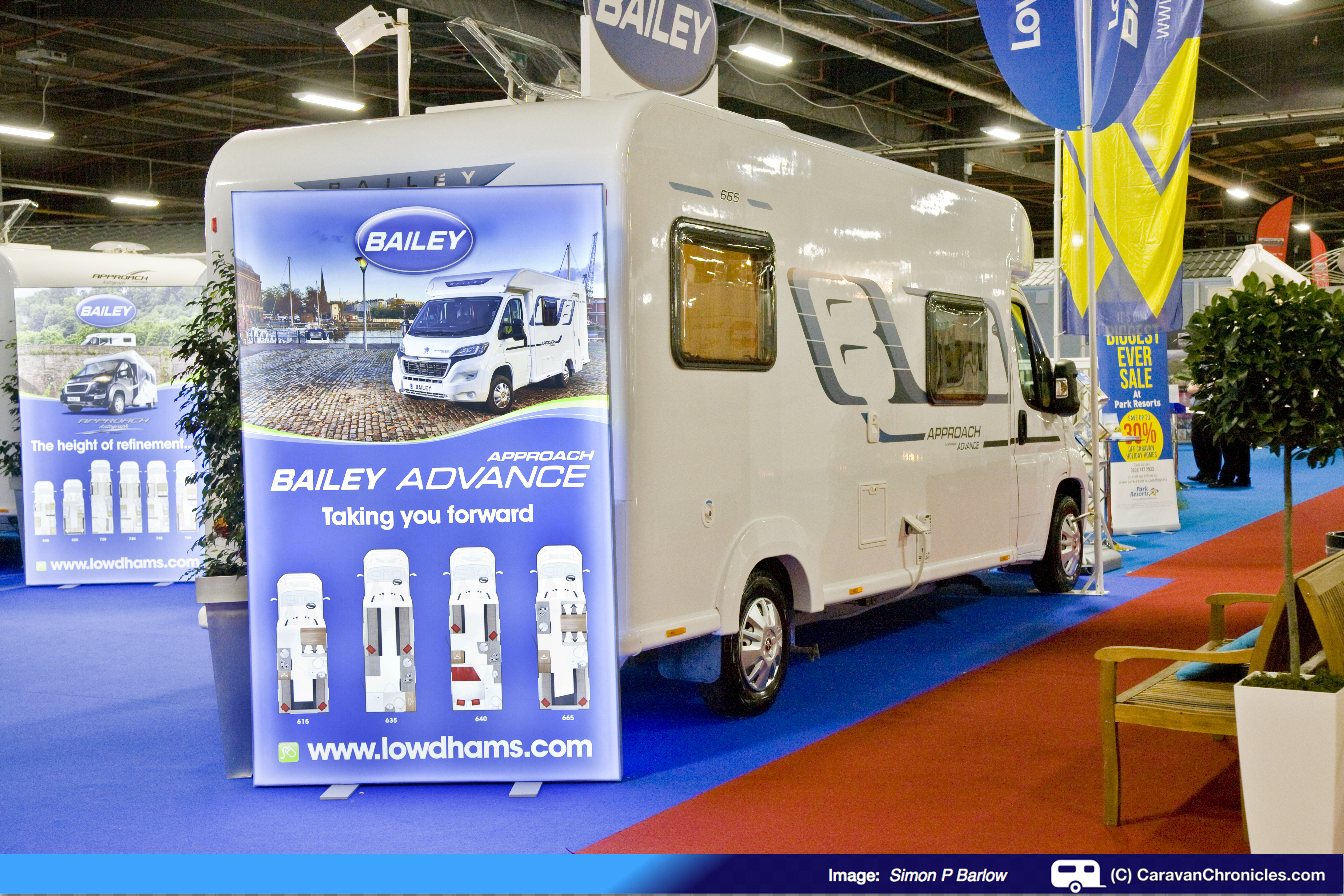
The other major caravan dealers in the north-west Lowdhams, Campbells and Kimberly covered the other manufacturers. It was noticeable though the tiny number of Bailey caravans on show although Lowdhams had a great selection of Bailey motor-homes on their stand.The Show Opens
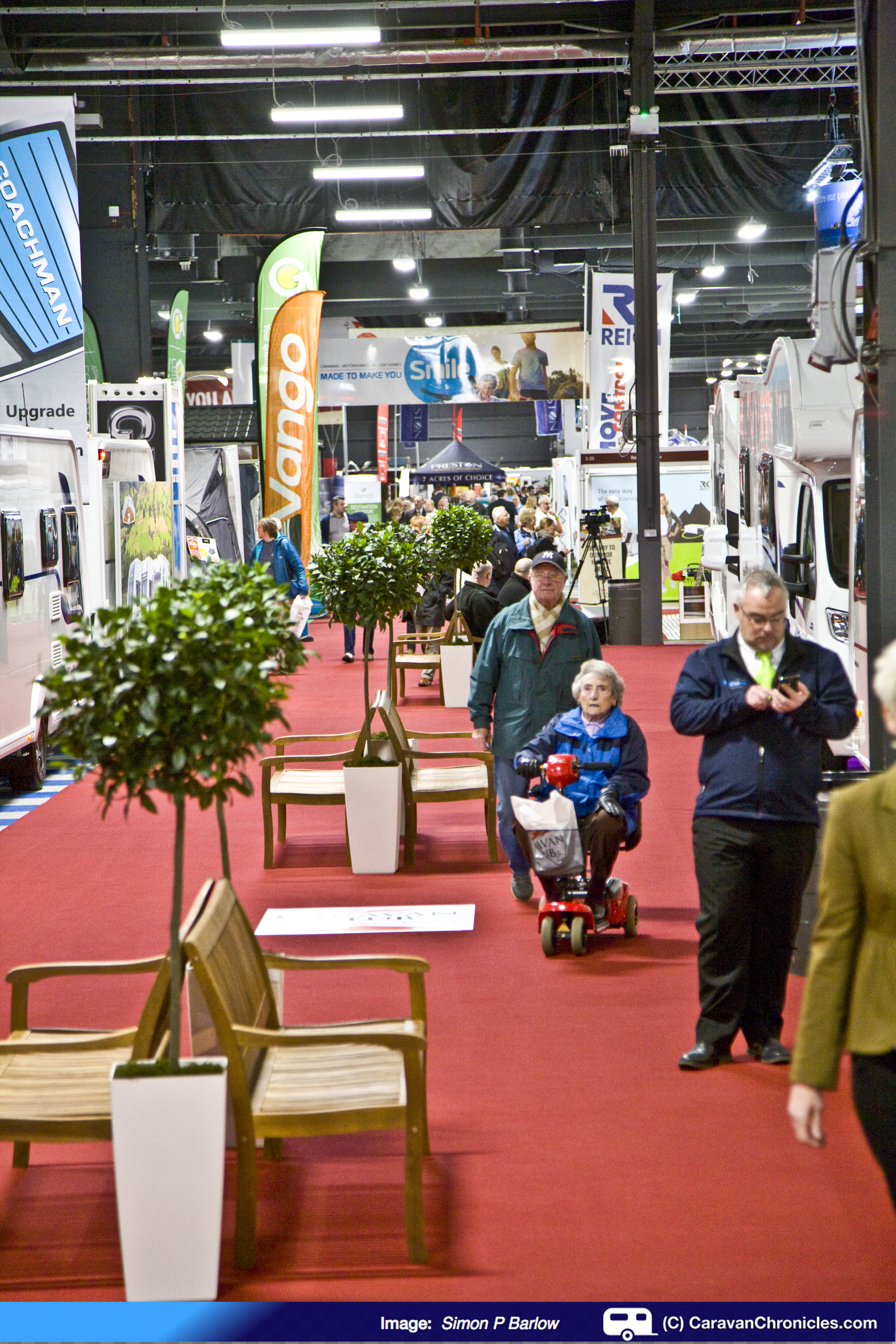
The show opened it’s doors promptly at 10:00 and the massed gathering outside in the entrance foyer flooded in. You could tell it was going to be busy.
10:00am and the doors open…
By now it was coffee and bacon and egg muffin time….. DISASTER! Non of the food retailers we checked out had a traditional show breakfast offering of the humble bacon and egg… or sausage and egg muffin. The nearest we came to it was the main food outlet that was doing Bratwurst rolls (I hope they weren’t a result of poor bratwurst sales at a Christmas market!) so two bratwurst rolls, one tea and one coffee (and £15 lighter in the wallet) had to do. I know the food outlets at shows normally charge a premium.. but seriously guys… £15.
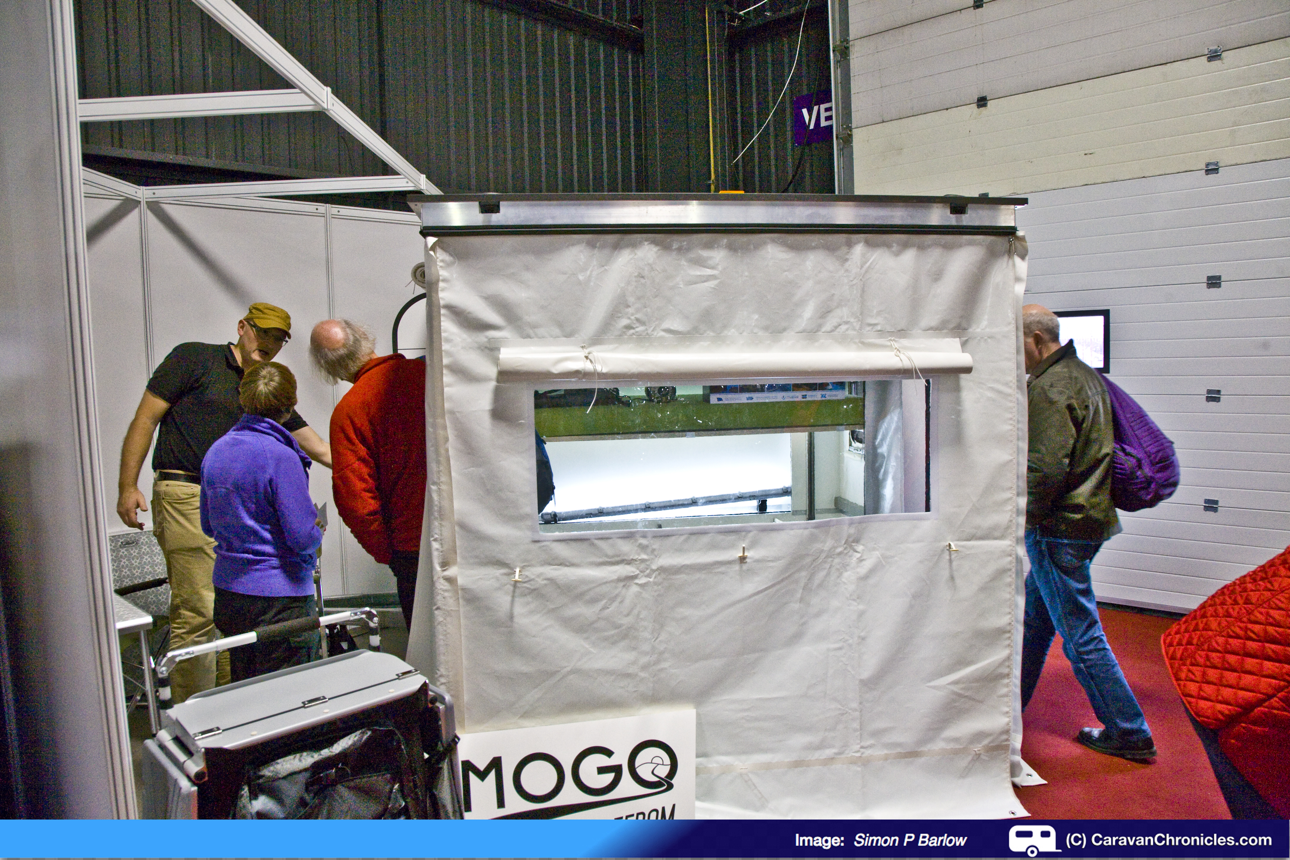
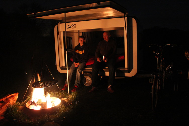
Something new…
One of the most innovative ideas at the show was something from a company called MOGO Freedom.
Matjaz Korosec and Ross Design from Germany followed the adage of less is more – the luxury lies in its simplicity. In its simplest form it’s a bed in a box… that you can tow. Now it’s not going to replace a caravan, but, and here is the clever bit, for avid campers that want something a bit more than a bit of canvas over their head at night but don’t want to give up the simple freedom of camping this might just be the thing that they are looking for. It is of course a bit more than a bed in a box. The bed rises up electrically to reveal a large storage area and both sides of the box open up to form a roof. The great thing about it is it will store in a normal size garage and it’s a maximum of 750 Kg’s so no towing restrictions for younger drivers.
Photo (c) MOGO Freedom Ltd
I think it’s a great idea as the all season alternative to a tent… go and have a look at the website… http://www.mogofreedom.com/
Other stuff…
Doing the rounds of some of the smaller exhibitors stands we chatted to the guys from Equipmart Ltd about their new KIAM inverter generators which really are pushing the price point for 1000 watt and 2000 watt inverter generators. Hopefully I’ll be able to include KIAM in a Caravan Chronicles generator shoot out and review later this year. (http://kiamproducts.co.uk/generator/petrol-inverter.html )
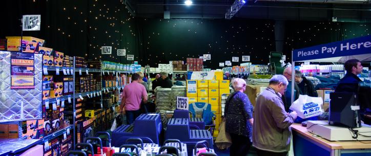
Make sure you don’t forget your wallet (or purse!) as Towsure once again are hosting the Towsure Accessory Superstore which has some great show deals. It always amazes me just how much stuff they can pack into their stand.
We did mooch round some motorhomes and as caravanners we can appreciate the different requirements that motorhomers and caravanners have for their particular chosen mode of accommodation. However we did come across Moto-Trek’s Euro-Trekka range and one in particular, the tag axle Euro-Trekka II did have us thinking… Hmmm. It has two slide out’s, a big 700 Kg payload and a 1600Kg towing limit. Only question is as Andy Harris asks… can you make toast in it?
So what did we think?…
Well if the crowds that we saw are anything to go by, I think it’s going to be another record-breaking show. It was great to see some new exhibitors to the show, especially Airstream and I hope that they and the others continue. All the stalwarts were there – Towsure, Isabella etc. Event City is an ideal location although I wonder how the show can grow apart from extending the number of days it’s open for. I did think that this year there were less leisure homes and lodges on show than previous years and maybe that one option would be to have these in a separate show all of their own so both could expand.
Definitely worth a visit, especially if you don’t want to travel down to the NEC next month.
The show is open Friday: 10 – 8pm, Saturday: 9.30 – 6pm and Sunday: 9.30 – 5.30pm and plenty of free parking.
Have you got the North’s biggest outdoor leisure show in your diary? 2015 promises to be a bumper year for the Caravan & Motorhome Show at Event City offering a huge choice of the latest models of touring caravans, motorhomes and holiday homes.
With over 300 exhibitors there is an incredible choice of new model caravans and motorhomes from all the leading manufacturers. In 2015, the show will feature more product launches than ever before, with new layouts being exclusively unveiled by leading manufacturers Bailey and Swift.
Last year the show saw a record breaking 27,917 visitors, with attendance up 13% on the previous year and 2015 aims to smash this target to be the biggest yet.
For the first time, in 2015, AIRSTREAM & Company will be exhibiting at The Caravan & Motorhome Show. Specialists in ‘cool camping trailers’, the team will be bringing a splash of silver to the Manchester event with three of its iconic brands set to be displayed.
Leading accessory retailer Towsure will be returning to The Caravan & Motorhome Show for a second year to host the Towsure Accessory Superstore. They will bring along their massive range of products from bike-racks to barbecues, sat-navs to outdoor furniture. Towsure will also be offering lots of special show-only offers and discounts too!
Visitors can swing by The Food & Travel Stage to see Simon Reeve, Charley Boorman and Martin Dorey from ‘One Man and His Campervan’ cook up their favourite dishes and tell tales from their many adventures.
Sam North, Show Director, said: “We’re hoping to build on the success of last year’s show and deliver the best show to date. The 2015 event will offer something for all ages; the return of Great Days Out will provide entertainment for all the family, while those on the hunt for a new caravan or motorhome can browse the extensive collection of the latest models.”
Sue and I will be there for the opening on Thursday 15th January and hopefully tweeting and posting updates directly from the show.
Part Two of our Cheltenham and Oxford festive outing…
Wednesday 10th December
Thankfully the wild weather that was affecting northern England and Scotland didn’t extend as far south as Gloucestershire and after a bit of a late start we were packed up and ready to say goodbye to Briarfields and set off for Oxford. We called in reception to drop off our electronic tag that operated the security barriers and waved goodbye to our neighbour who was leaving in his campervan after an overnight stay. The Sat-Nav gave a distance of about 37 miles and a time of one hour twenty minutes to complete the journey. We pulled off the site just before eleven o’clock and headed out into the late morning traffic enroute for Oxford Camping & Caravan Club site.
We hadn’t being travelling long when Sue produced a ten pound note out of her pocket… “That’s the deposit for the electronic tag.”
“Hmm I don’t remember paying a deposit”
When Scott booked us in I think he forgot to take a deposit, and Jo assumed he would have and gave Sue ten pounds back. So apologies Scott and Jo, we seem to be ten pounds up on the deal, just means that we have an excuse to return next year to give you the money! Mind you, I don’t think we need an excuse as there is still so much to see and a visit to Gloucester in the summer is definitely planned.
The trip took us through the beautiful rolling hills of the Cotswolds, the sun was shining and it was a pleasant drive to Oxford. We had stayed at the Oxford C & CC site a number of times before as it is convenient for exploring Oxford. It does have a downside though. It can be noisy as the main Oxford to London railway line runs only a couple of hundred meters away and through the night there is plenty of railway freight run on that line. Additionally there is a large factory that sometimes can be noisy. All that said, the advantages tend to outweigh the disadvantages.
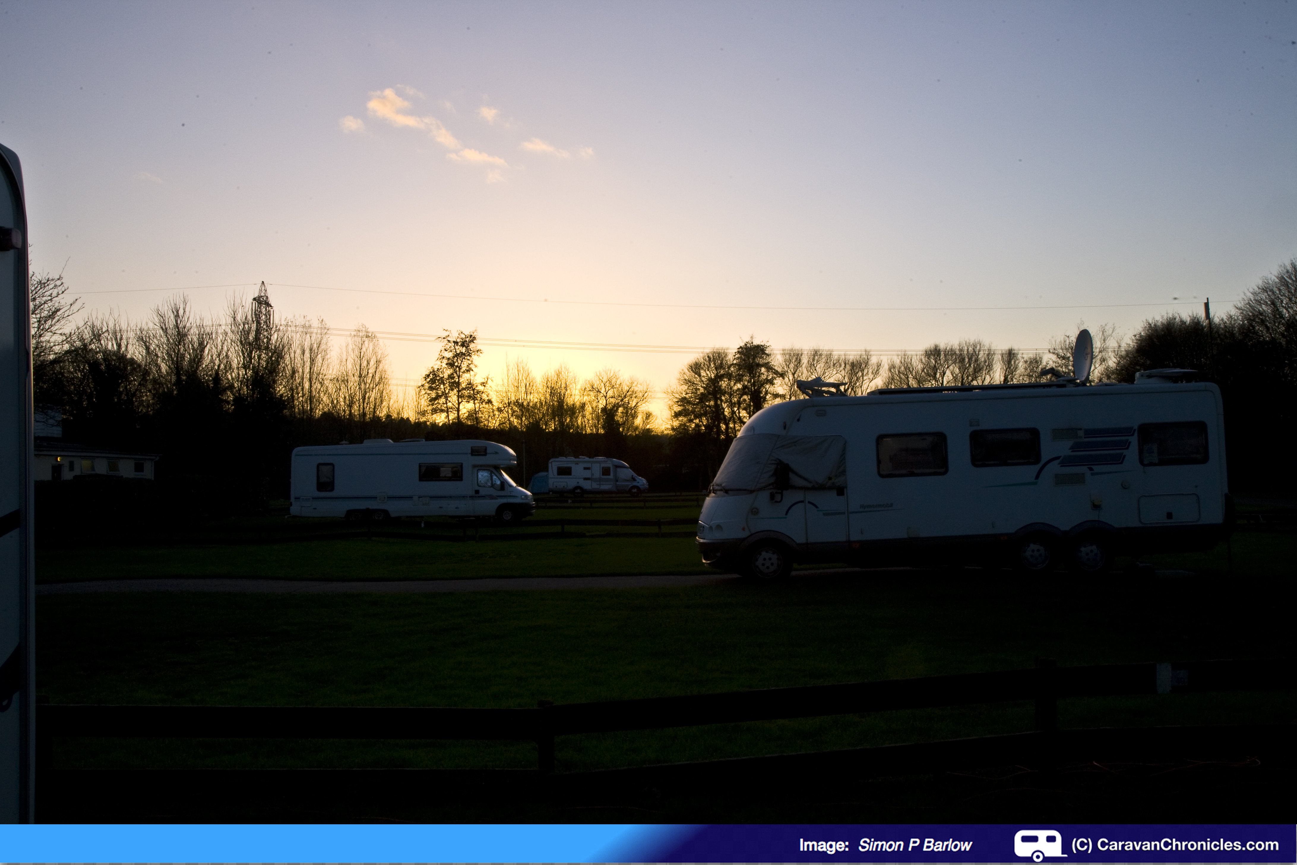
We arrived at the site about 12:20 and checked in. During the winter months the site has to run on a reduced number of pitches due to the ground conditions and motorhomes are parked on the tarmac road areas. We were shown to our pitch which was on the northern side of the site. The grass wasn’t too soft but had obviously been wet for a number of days.
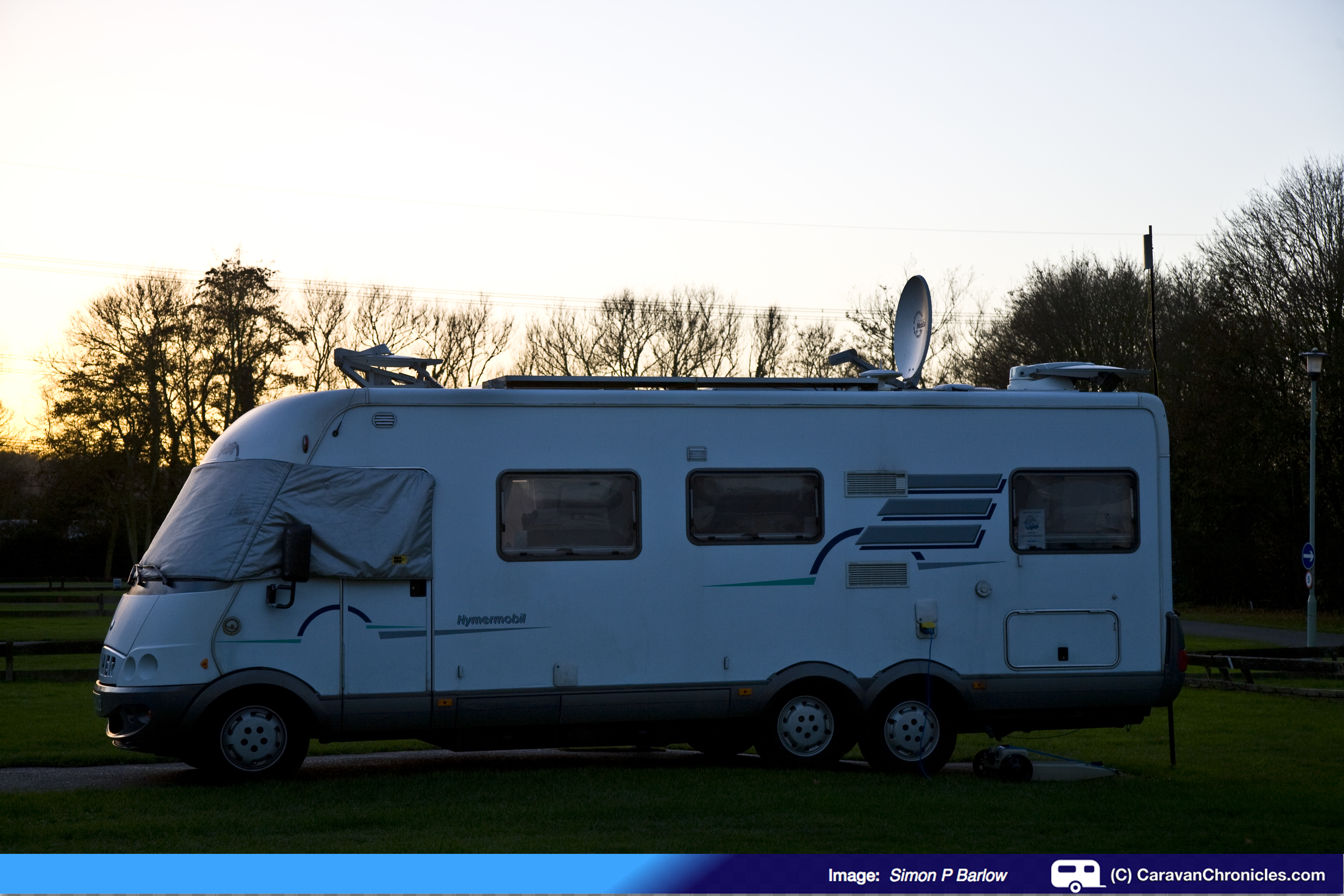
That evening the clear skies of the day gave way to a drop in temperature as the sun set. Behind us was a Hymermobile Motorhome, which had three satellite dishes on the roof. Now it was either an outpost of Mission Control or Andy Harris of the Motorhome Channel had upgraded to a Hymer…. but we could not smell any fresh toast being prepared, so discounted that idea.
Had Andy Harris upgraded to a Hymer?
A quick trip to Aldi to stock up on Gluevine and a few other essentials and a quick wander round Go Outdoors finished off our day.
Thursday 11th December
The weather forecast for the day was generally windy and rain but Friday looked like it would be clear again so we decided to put off our visit into Oxford for the Christmas market until then. Sue had always wanted to go Blenheim Palace and thought it would be a good destination for the day. Checking on-line they had Christmas events and it was looking promising. I checked the ticket price and was floored at the cost. For the two of us for the Christmas attractions it would be just over £45 to get in. As we were mulling that over I clicked on Trip Advisor and read some of the reviews for the Christmas event…. there weren’t many but most complained about the cost and there wasn’t actually that much to see. However one lady that had posted a review (Margaret151151 ), her last line was “…Now our visit to Waddesdon at Christmas WAS well worth the money!”
A quick ‘google’ soon found the website and it did look interesting and the ticket price a more reasonable £36 for the two of us. Decision made, I bought the tickets on line which gave us timed entry into the house and Sat-Nav programmed we set off for Waddesdon. Located on the A41 between Bicester and Aylesbury it didn’t take very long to get there.
The house is the former home of the Rothschild family… (or some section of it… I’ve not read up on it yet) and is set in wonderful landscaped gardens. While most of the house was closed for its annual winter deep clean, one wing was still open and had been decorated for Christmas… with dozens of Christmas trees grown on the estate specifically for certain rooms in the house, so the height and width of the tree had been monitored to ensure an exact fit… here is just a few:
The trees and decorations were all themed for the rooms and they really were spectacular. Not often I stand in front of a Christmas tree(s) speechless! The timed entry into the house really worked well and there wasn’t a mass of people who could make enjoying the spectacle a disappointing experience.
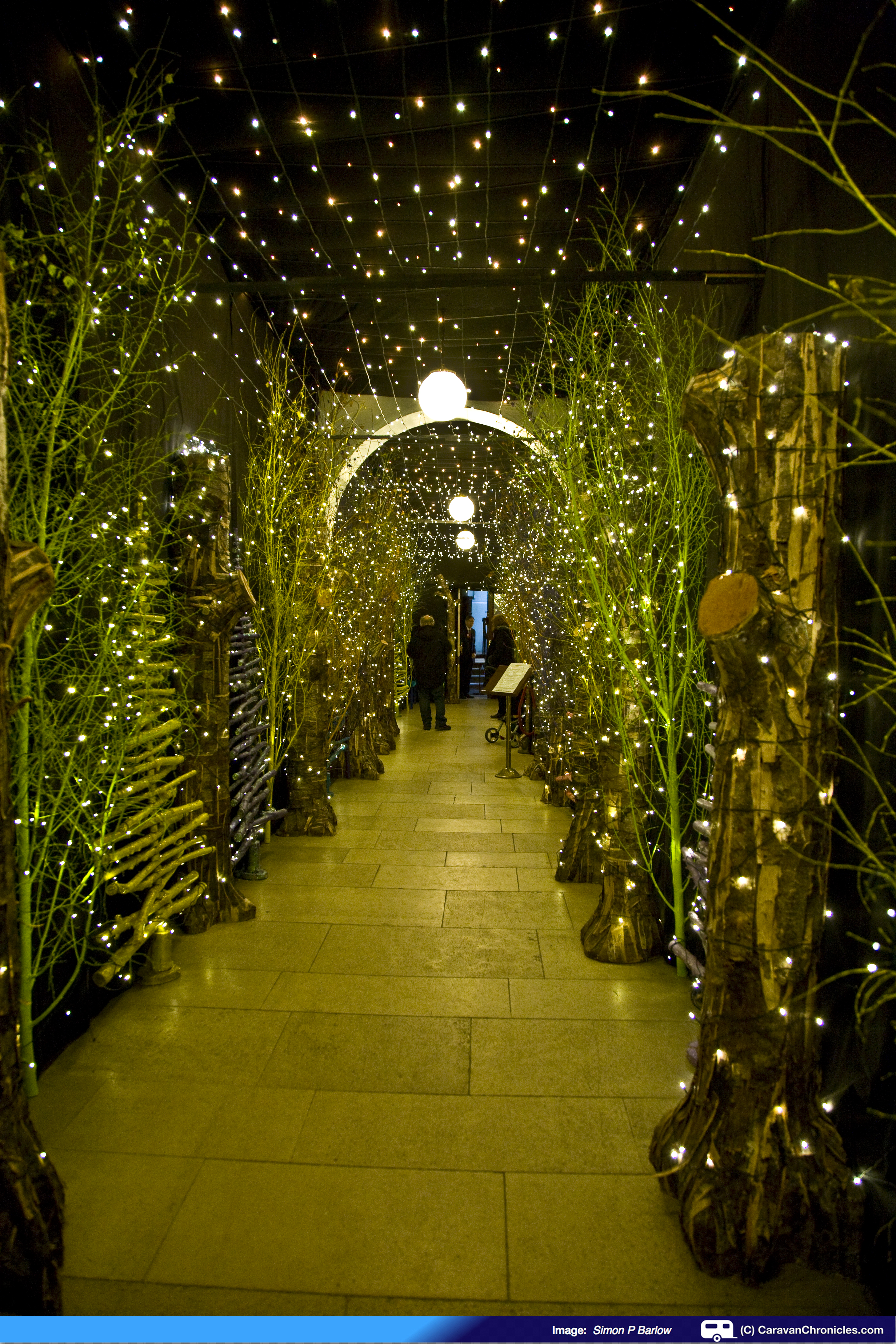
The corridor from the Manor shop to the restaurant
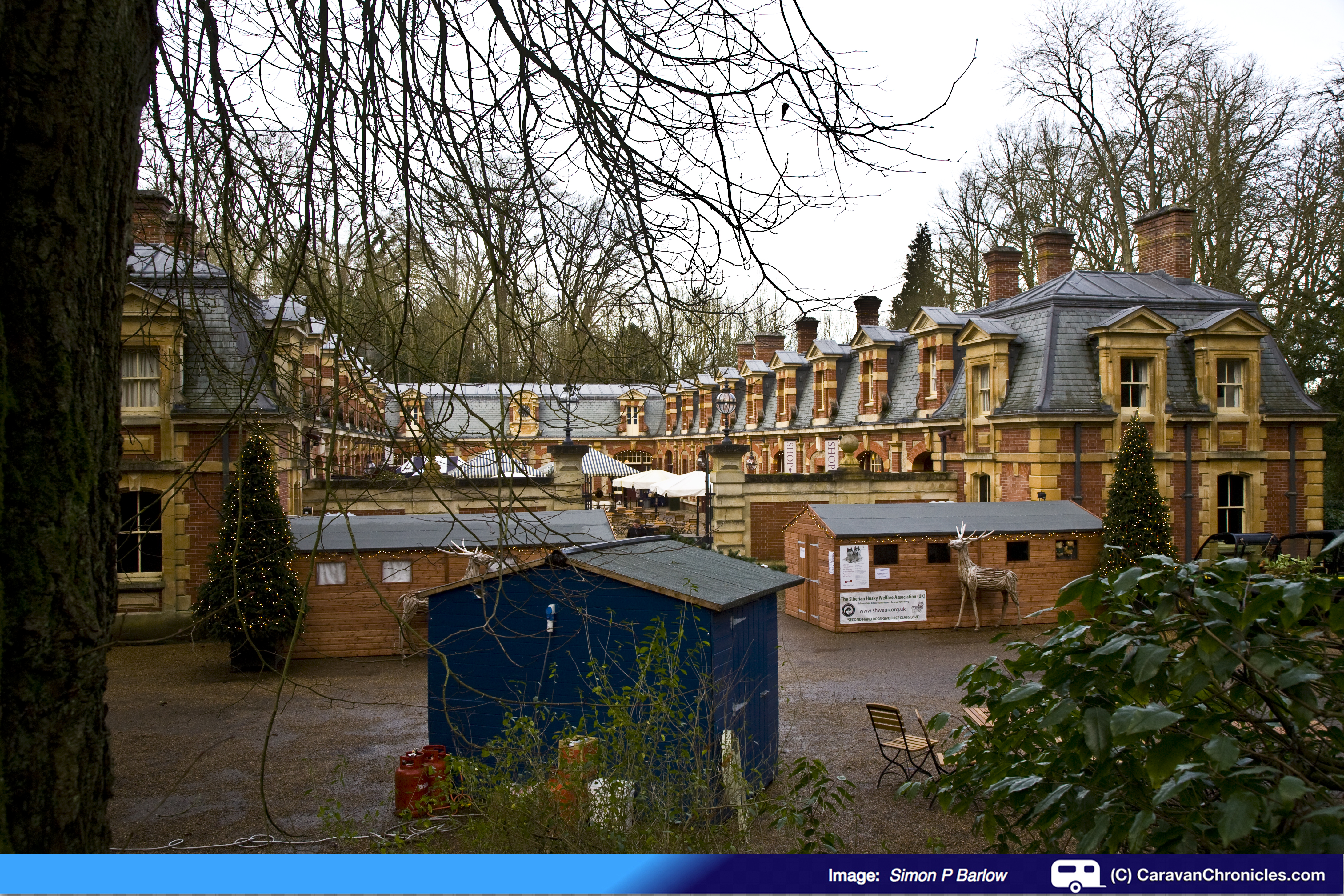
From the house we headed down to the stable block, a short walk from the main house to the cafe and shops. If we had been there a couple of days earlier we would have also had chance to visit the Christmas market that is also held there.
The impressive and lavish stable block now houses shops and a cafe
A late lunch in the cafe followed by a walk round the Bruce Munro light installations in the grounds in a vain attempt to walk off the calories.
Waddesdon is somewhere we are planning to return to so we can see the rest of the house. We both would recommend it as a definite ‘to do’ on anyones list of Christmas places to visit.
All too soon we were back on the road towards Oxford again… it was fast approaching mulled wine time.
Friday 12th December
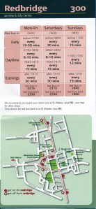
The weather wasn’t quite as promised but it was clearing slowly. We walked across to the Park & Ride stop opposite Go Outdoors to catch the number 300 service into the centre of Oxford.
Just as we arrived, it started to rain again so we headed in the direction of the indoor market for a mooch round in the dry. By the time we had come out the rain had stopped and we set off towards the Christmas market. Sue had an Italian version of mulled wine (well it is nearly Christmas!) while we wandered around the many stalls. As always is was rapidly approaching ‘lunch o’clock” again and we kept an eye out for a suitable place. Last time we were in Oxford it was with our friends Pete and Julie (Julie sadly passed away last year) and we had tried to get into “Jamie’s” – Jamie Oliver’s restaurant but it was full. This time we managed to beat the crowd.
We decided on a light lunch and opted for…..
JAMIE’S ULTIMATE SHARING PLANK
£10.50 PER PERSON
For two or more to share. Artisan fennel salami, mortadella, spiced chicken-liver pâté, truffled salami & fennel pork scratchings with grissini & music bread, Cauliflower fritti,mozzarella & aged pecorino, tomato mostarda & crispy shallot rings, Olives & pickles, grilled marinated peppers, & crunchy kale slaw
… and a carafe of house white.
Now I’m not sure what I was expecting. It was nice with a good selection but maybe I was expecting more of a ‘wow’ than I got. Service initially was a bit slow off the mark but there was a Christmas party of around 20 people starting to arrive that seemed to delay things a little. The service did improve after the party group got sat down. The lunch was enjoyable and the atmosphere in the restaurant vibrant. However… I was missing the ‘wow’ that I thought I’d get… not sure what the ‘wow’ should be but there you go.
We headed out again to cover a few more shops and to do another turn round the Christmas market – just in case we had missed anything. The light was starting to fade and all the Christmas lights decorating the streets came on. Deciding it was time to head back we retraced our footsteps back to the bus top to catch the 300 back to Redbridge Park & Ride opposite the caravan site.
Saturday 13th December
The temperature on the digital thermomiterbob said minus 2.6 degrees outside and it felt like it as it was only 10 degrees inside the caravan (OK who turned the heating on to the lowest setting then… that would be me!)
It was a bit of a lazy start packing up – Sue attended to all the inside ‘pink’ jobs while I looked after the outside ‘blue’ jobs. Thankfully the water in the Aquarol and the wastehog hadn’t frozen. I drained the loo flush tank back into an empty container and just before 11 we were ready to hitch up.
Now this is the first time that this has happened to us. The pitches at Oxford are lower than the tarmac road and on hitching up I discovered that due to the Freelander still having the front wheels on the road, the tow ball was so low I could not rotate and raise the jockey wheel so we had to unhitch again. We struggled and swung the caravan round so we were at an angle to the road and hitched up again… same problem. So we had to unhitch and swing the caravan enough so that the front wheels of the Freelander were off the road, hence lower so hitching up for a third time finally gave us the clearance to swing the jockey wheel round under the A frame and raise it.
It’s my fault as one our very first trip to Oxford with the caravan we had hired I watched someone have exactly the same problem… I should have remembered. By 11:30 we were pulling out of the site heading for home.
Surprisingly the roads were quiet. The A34 onto the M40 was very quiet and we made good time. On the M40 a National Express coach driver after taking about 40 seconds to actually overtake us (we were doing about 55 mph) decided that he didn’t actually need to know if he was clear and just pulled in without indicating with about ten inches clearance between the back of his coach and the front of the Freelander. I wish we had one of those CCTV camera recording do-hickeys.
A brief stop at Norton Caines services on the M6 Toll road and using the Caravan Club membership card to get our discount at the toll plaza we hit the M6, which even though there are road works at the M6 / M6 Toll junction was free-flowing and no delays. The rest of the M6 north was quiet too… we had never seen it run so freely even on a Saturday. By 3:30 the caravan was parked up in its storage bay and we were off home… time to go and give ‘the boys’ (our three Siamese cats) a good ‘polish’
Summing up…
Six days, three cities, two christmas markets… done!. Visiting Christmas markets is a great way of getting in the festive spirit. We used christmasmarkets.comto find out when and where the Christmas markets are. If you can’t get out in your caravan this year to a Christmas market…. start planning for next year or we might beat you to it!
The sites…
Briarfields is ideally located for exploring Cheltenham and Gloucester at any time of the year. With the additional on site motel, it’s great if you want to explore the area with family or friends that don’t have a caravan or motorhome. The site is well maintained and the facilities are spotless and it offers free WiFi. It could do with another Grey Water Disposal point though.
It is however about 1 mile (1500 metres) from the threshold of runway 27 at Gloucester airport so there will be aircraft passing overhead at around 300 to 400 feet but don’t let that put you off. They are mainly small single engine aircraft with the odd executive jet and the noise is not obtrusive. The airport operates restricted hours so the aircraft won’t be passing overhead all night. If you are an aircraft spotter it’s ideal!
Time it right and you can do Gloucester Victorian Christmas Market and Cheltenham Christmas Market in the same visit. I would suggest you book early though as it will fill up quickly, especially at Cheltenham Gold Cup time.
Would we return to Briarfileds? – Yes. Would we recommend it? – Yes.
Oxford C & CC site is ideal for exploring Oxford as it’s so easy to get into the centre by bus or walking beside the river. Oxford is a great place to visit any time of the year and is one of those cities you want to go back to time and time again. The Oxford C & CC site is a little tired, but well-kept. As the site is actually owned by Go Outdoors the C & CC club do have limitations on what they can do there to improve things. There is the known noise problem from the railway line, but in fairness it’s not constant like a road.
Would we return to Oxford C & CC? – Yes. Would we recommend it? – Yes.