• Home
  • Help Guides
    • Storage Sites
    • Equipment Reviews
  • Document Library
    • Electrical Drawings
  • Photo Gallery
    • Caravan Log
    • MPG
  • Trip Map
  • Shop
  • About Caravan Chronicles…
  • Contact
  • Links

Caravan Chronicles

~ not just another caravan blog

Caravan Chronicles

Category Archives: Caravan Servicing

Something For Your Toolbox…

03 Wednesday Apr 2019

Posted by Simon Barlow in Caravan Electrical Fault Finding, Caravan Electrics, Caravan Fault Finding, Electrical, Maintenance, Technical

≈ 7 Comments

Tags

Earth Side Testing, Electrical Fault Finding, Technical

A few weeks ago I posted a blog post called “A Quick Fault Finding Tip…” and that  generated quite a few emails regarding electrical testing and how to trace faults.  In fact a lot of the other electrical posts I’ve done over the years still generate emails and comments (it’s always worth checkingback on some of th eolder posts to read the comments) I’m going to try to explain a technique that’s really handy to have in your tool box for general fault-finding.

Earth Side Testing

Most people who perform general maintenance on their vehicle, motor home or caravan will be familiar with checking the voltage of the vehicle or leisure battery using a multimeter. Great little things to have and personally I think everyone should be able to do the basics with one.  So as a bit of a refresher I’ll go through this scenario with you. Checking the lights on your tow vehicle you notice one of the brake lights is a lot dimmer than the other. Let’s find out why. I’m going to simplify the circuit a bit it should give you the idea behind the principle.

Depending on the device you re reading this on the drawings might be small. If you want to see the drawing full size just click on it to open it up full size.

Earth Side Testing 1-0

In the drawing above you can see the basic circuit. The positive lead from the battery goes through the ignition switch and on to a fuse. From there through a connector to the brake pedal switch and on to another wiring loom connector to the back of the vehicle. It passes through another connector before arriving at the brake bulb holder. The holder is connected to the vehicle chassis via another wiring loom connector. The vehicle chassis is connected back to the battery in the engine bay. You can see we’ve checked the battery voltage with out meter and it reads 12.68 volts… so not a flat battery. We’ll make a note of the battery voltage.

OK… so the problem is this bulb  is not at full brightness.. so it’s got to be a loss of voltage supplying it somewhere in the circuit. We need to check the voltage along the circuit with the bulb lit (circuit live) and the black negative lead of our multimeter attached the battery negative terminal. (I’ll explain how to do this later).

Earth Side Testing 1-1

Probably the next place to check it would be the fuse… 12.66 volts, not too bad only 0.02 or 20 mV loss… lets keep going….

Earth Side Testing 1-2

..next is a wiring loom connector, back probing it gives a 10 Mv drop (loss) normally these modern connectors are pretty good.

Earth Side Testing 1-3

Brake light switch… Hmm a bit more of a drop… maybe a quick spritz with contact cleaner will sort that…

Earth Side Testing 1-4

Back probing the next connector gives a bit more of a loss… I’ll come back and check the brake light switch connector.

Earth Side Testing 1-5

OK, now at the back of the vehicle and a bit more of a drop at that connector but nothing too much…

Earth Side Testing 1-6

Well 12.13 volts on the bulb contact… so between the battery and bulb positive tip a total loss of 0.55 V or 550 mV…. that’s about within limits as I would not expect to see much more than a 500 mV… half a volt drop on a typical circuit like that. So what’s going on? A 500 mV drop can’t account for the dim bulb?

However, if we keep going and measure the voltage on the earth side of the bulb holder….

Earth Side Testing 1-7

Hang on we see a reading of 2.67 volts. How can that be? We are connected to ground at both ends of the meters test leads? A circuit has two sides, the positive side to the load – in this case the bulb and the return or negative side back to the battery.

Just because the negative wire on the bulb holder is only short and goes to a bolt securing it and maybe many others to the chassis doesn’t mean we can assume it is the same as being clamped to the negative battery terminal.

A few things to ponder…. vehicles are made of steel… steel is not as good conductor of electricity as copper… nether is aluminium that some vehicles have in their construction. At one time steel panels were all spot welded together… now a lot are bonded on with specialist adhesives. The earth point may well be in the boot or under the floor and will be subject to corrosion as will the main battery neutral cable in the engine bay. All this can compromise an electrical path back to the battery.

If we look at the voltage drop on both sides of the circuit we have 0.55 volts on the supply added to 2.67 volts on the neutral side…. 3.22 volts in total, so we are trying to light our bulb with only 9.46 volts.

Could we have got there quicker?

One of the checks I always do first with the ignition on is the battery voltage check to get a reference to work with and then simply move my red positive test lead over to some main point on the engine block….

Earth Side Testing 1-8

If I get a reading of more than 0.4 volts (400 mV) obviously my negative return path from the vehicle chassis is compromised. Time to turn everything off and undo the main earth cables to the chassis and engine and give them and the mounting points a good clean with scotch bright or fine emery and a dab of specialist grease (see “Shopping” below) to protect them from further corrosion.

In the scenario we have just gone through, I’ll bet a wet weekend in Blackpool that cleaning both the earth terminal at the back of the vehicle and the battery earth to the chassis would have sorted the problem. I’d also have a look at the brake pedal switch as there is a bit more of a voltage drop than I’d like. Most likely it’s the connector rather than the switch itself.

For those that tow…

Nearly all tow bar wiring looms will ground to the same point in the back of the vehicle with some of the other assorted vehicle earth cables…. installers take the easy route and if there are already cables earthed there … then another couple won’t make a difference.

This can and will have an effect on the performance of your caravan electrics. Both the leisure battery charging circuit and fridge circuit will probably be earthed at that point.. So in the case of the fault above, each of those circuits will have a voltage drop of 2.67 volts. Therefore if you have leisure battery charing or fridge issues its possibly not the wiring in the caravan,  it could be the wiring in the vehicle. Check the ground path first.

One quick check is with lights and ignition turned on, do a volt drop test between the battery negative terminal and one of the cable secured under the earth point at the rear of the vehicle where the tow pack electrics are terminated. If it’s above 0.5 V (500 mV) then give the earth points a clean.

One bit of advice I’ve given to people in the past is to run a 4mm or 6mm cable directly from the negative battery terminal to the back of the vehicle and terminate it at the earth point where all the rear lights and tow electrics terminate. Makes a heck of a difference.

Back Probing…

Frankie-Howerd

Right…. Franky Howard fans stop it now! Back Probing, you might have heard of it and really it’s nothing special. It’s a simple technique used when fault-finding and involves using a fine probe to get into the back of the connector where the cable enters to test the voltage without disconnecting the connector. Sometimes you can get away with a straightened paperclip wound round the tip of the multimeter test lead. You can buy test lead accessory packs that have various attachments or ‘caps’ that fit on the end of your test leads to make the task easier.

Screenshot 2019-04-03 at 11.11.25

How do I test between the battery and some other point on the vehicle or caravan?

I have made a few of these over the years… basically it’s a long length of wire, about 20 feet with a battery terminal sized crocodile clip at one end and a small crocodile clip at the other… and I don’t know how many I’ve given away to people. I have a couple, one long enough to get tot he back of the vehicle and one long enough to get to the back of the caravan when its hooked up to the vehicle. SImply clip one end to the battery negative terminal and the other to the negative lead on your multimeter. Often its an idea to tie a loose knot in the two leads to stop them coming apart. Caution though, this lead is connected to the ground side of the battery – don’t let it dangle where it might touch something… put a bit of tape for protection around the connection if required.

Shopping…

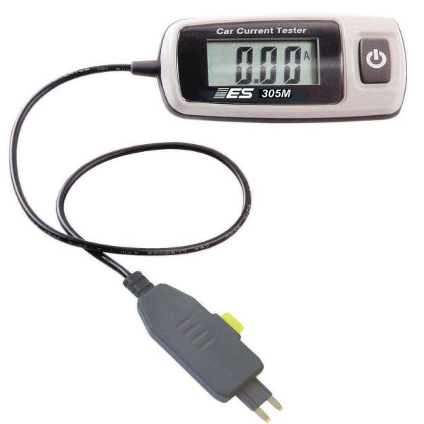
Multimeters…. a person can never have enough multimeters…. and since the demise of Maplin a couple of great places to keep an eye on is Aldi and Lidl. I got a couple of great general purpose multimeters from Aldi for £9 each. Not always available as they generally come up as special buy’s. However if you are an Amazon shopper then this https://amzn.to/2I91q91 seems like a great little multimeter with a lot of positive reviews for £12

I use Liqui Moli 3140 Battery Clamp Grease – https://amzn.to/2Vn0qSo for battery and chassis terminals. It’s a small tube but does last a while.

If you want to make your own long test lead this box of crocodile clips https://amzn.to/2VedU32 for about £4.50 is always handy.

A dream test tool…

If you are into testing or it’s part of your job then there has been something on the market for a while called “Power Probe” Now while the original is obscenely expensive and there are a number of copies out there. The Auto Power scan PS100 is priced at about £80 and does the job in one simple instrument – https://amzn.to/2OJHYAW (Any sponsors out there… hello….hello…) This is on my “I really want one of those” list!

Finally…

"Oscar" our senior safety cat.

As always when working on anything electrical think safety. Oscar our Health & Safety Cat would like to remind you that working on vehicle electrics can be just as dangerous as working on house electrics. If you are unsure then DON’T…. get in touch with someone who is qualified. Find the right person and they will usually help you to do it safely. Be like Oscar – Be Safe.

  • Related posts you may like…
  • A Request…
  • The problem with information from the internet…
  • Euro 6 Engines, Smart Alternators and Your Leisure Battery…
  • For Anyone Restoring A Vintage Caravan…
  • Overland Vehicle Electrics and Other Stuff…
  • A Quick Fault Finding Tip…
  • Something For Your Toolbox…
  • Getting All Charged Up – Update 2…
  • Is A Euro 6 Engine Killing Your Leisure Battery?…
  • Getting All Charged Up – Update
  • Getting All Charged Up – Part 3 “The Install”…
  • Getting All Charged Up – Part 2…
  • Getting All Charged Up – Part 1…
  • Smart Alternators: how they affect Caravans and Motorhomes….

Share this:

  • Share on X (Opens in new window) X
  • Share on Facebook (Opens in new window) Facebook
  • Share on Tumblr (Opens in new window) Tumblr
  • Share on Pocket (Opens in new window) Pocket
  • Share on Pinterest (Opens in new window) Pinterest
  • Share on Reddit (Opens in new window) Reddit
Like Loading...

A Request…

09 Sunday Dec 2018

Posted by Simon Barlow in Blog updates, Caravan Electrical Fault Finding, Caravan Electrics, Caravan Fault Finding, Caravan Servicing, Electrical, General, Help Guides, Maintenance, Motor Home, Technical

≈ 11 Comments

Tags

Fuse Voltage Drop Table, Relay Wall Chart, Technical, Wire Size Chart

Ok, not one of my usual blog posts. I get a lot of email asking about various electrical items related to caravans and motorhomes and a few things seem to keep cropping up on a regular basis. One is to do with 12 volt relays… what types are there and what are the pin connections.

Another is to do with cable size relating to load and its relation to the length of cable…. “I have a 40 Amp load and its 3 metres from the battery… what size cable do I need?” type questions.

In the past I’ve emailed back with answers, but one caravan engineer asked me if I know of any information sheets that had this type of info that he could put above his workbench.

So I’ve produced a couple of A3 size PDF information sheets (they will print A4) that can be downloaded printed out and pinned up, shoved in your notebook, glued to the lid of your tool box or used to wrap that must have tool present for your beloved caravan or motorhome DIY enthusiast in your life (seasonal eh!)

(I have been told that Office World can print and laminate A3 PDF’s cheaply…. I never knew that!)

Screenshot 2018-12-09 at 10.23.41

Click here to download the  Relay Wall Chart

Screenshot 2018-12-09 at 10.24.11

Click here to download the   Wire Size Wall Chart

Screenshot 2018-10-11 at 16.52.54

Click here to download the Fuse Voltage Drop Table

I have stylised them as technical drawings and I’ve had to watermark them and some of the icons as I found a lot of my drawings were ending up “as is” or edited on various sites and forums without any credit or link back to Caravan Chronicles. You are free to print out and use them for your own personal use, but if you wish to use them (or any of my drawings) for commercial use, inclusion in blog posts or forums please include a credit line back to CaravanChronicles.com and drop me a line to let me know.

We are just back from Chester Fairoaks after doing the Chester Christmas market and a bit of shopping at Cheshire Oaks Designer Outlet Village and will be adding off to York for a bit more Christmas Market action.

I have a couple of more information ‘posters’ in development but if you have any ideas for future offerings, drop a line in the comments below. Of course my legal advisor – Henry has asked me to point out E & OE

(Everything on the internet is improved by a cat apparently… so here’s Henry)

IMG_2176
  • Related posts you may like…
  • A Request…
  • The problem with information from the internet…
  • Euro 6 Engines, Smart Alternators and Your Leisure Battery…
  • For Anyone Restoring A Vintage Caravan…
  • Overland Vehicle Electrics and Other Stuff…
  • A Quick Fault Finding Tip…
  • Something For Your Toolbox…
  • Getting All Charged Up – Update 2…
  • Is A Euro 6 Engine Killing Your Leisure Battery?…
  • Getting All Charged Up – Update
  • Getting All Charged Up – Part 3 “The Install”…
  • Getting All Charged Up – Part 2…
  • Getting All Charged Up – Part 1…
  • Smart Alternators: how they affect Caravans and Motorhomes….

Share this:

  • Share on X (Opens in new window) X
  • Share on Facebook (Opens in new window) Facebook
  • Share on Tumblr (Opens in new window) Tumblr
  • Share on Pocket (Opens in new window) Pocket
  • Share on Pinterest (Opens in new window) Pinterest
  • Share on Reddit (Opens in new window) Reddit
Like Loading...

A Quick Fault Finding Tip…

12 Friday Oct 2018

Posted by Simon Barlow in Caravan Electrical Fault Finding, Caravan Electrics, Caravan Fault Finding, Caravan Servicing, Electrical, Technical, Tips

≈ 18 Comments

Tags

Caravan Electrical, Fault Finding, Maintenance, Technical, Tips

Sometimes things you take for granted and have in your toolbox of fault-finding tricks are a dark art to others.

I was talking someone through a bit of fault-finding on their vehicle and asked if they had measured the current in the circuit. “No” came back the answer. I asked what type of fuse and rating it was and asked the person to just put their voltmeter across the fuse and tell me the voltage across the fuse. “Ah… that’s about 3.2 amps then” I said.

“How do you know that?”

Simple really – all fuses have a resistance and if you know that you can work out the current from the voltage drop. Even simpler really – there are tables for various fuses that have it all worked out for you. I have a selection collected over the years stuffed into the lid of my tool box, along with a lot of other junk paperwork!

I created a volt drop table based on PEC (Pacific Engineering Corporation) fuses that are supplied as OEM fuses in most Japanese, Korean and European vehicles however it is pretty accurate for almost all other makes of the same type of fuse. I printed mine out, laminated them and added them to the collection in the top of my toolbox.

Screenshot 2018-10-11 at 16.52.54

It’s quite easy to use. Just set your multimeter to read DC mV and read the voltage displayed. Now select the fuse type, in this case an ATO fuse – the most common used in vehicles, caravans and motorhomes and from the chart look down the left column until you see the voltage measurement that matches the one on your multimeter… lets say 0.011 volts (11mV)

The fuse is a red 10 Amp fuse so follow the 0.011 volt line across until you get to the 10 Amp fuse column and read the current figure… in this case 1.3547 or 1.3 Amps. It’s as easy as that, no need to break the circuit to put your multimeter in as an Ammeter.

fuse-buddy-specialty-meters-esi305m-64_1000
I have a couple of these cheap handy plug-in ammeter’s…  although they do have limitations and only work up to 20 Amps.

Although the table is based on PEC ATO/ATC and MINI fuses (download info below) it is pretty close with most manufacturers fuses and as a general reference for fault-finding will be good enough to 0.1 amp.

If you need to know the actual current through a circuit, you need to use an ammeter and not rely on tables but for general work they are close enough.

These tables also come in handy if you are trying to find out why a battery is draining. Without turning anything on it is easy to run through a fusebox checking to see if any circuits have a current drain on them without having to constantly pull fuses and insert an ammeter, which sometimes can upset or reset the circuit you are working on.

One thing to remember with this test if you’re tracing a fault, is you are only measuring the volt drop across the fuse to determine current. You really need to know how much current you should be drawing. For example, If I was testing the 12 volt fridge circuit fuse and I only got a voltage drop across the fuse that calculates to 6 Amps then I’d know there was an issue somewhere along the circuit as I’d be expecting around 10 Amps or more.

A word from our Safety Officer…

"Oscar" our senior safety cat.

Oscar would like to remind you that working on a live circuit has risks and never attempt to undertake volt drop measurements on mains circuits. Most cheap multimeters do not have the internal protection or fused test leads. Be safe. Be like Oscar.

You can down load the table in PDF format (4 pages) and either print them out or save them to your device from the following link: Fuse Voltage Drop Table

Unfortunately due to a lot of my drawings and text being used elsewhere without credit back to CaravanChronicles.com  I’ve had to start putting watermarks on a lot of things. I hope this doesn’t make the table too difficult to read.

P.S. Someone told me that everything on the internet can be improved by cats and my “likes” would go through the roof!

Share this:

  • Share on X (Opens in new window) X
  • Share on Facebook (Opens in new window) Facebook
  • Share on Tumblr (Opens in new window) Tumblr
  • Share on Pocket (Opens in new window) Pocket
  • Share on Pinterest (Opens in new window) Pinterest
  • Share on Reddit (Opens in new window) Reddit
Like Loading...

Catch Me If You Can… Part 2

28 Thursday Jun 2018

Posted by Simon Barlow in Accessories, Amarok, General, Help Guides, Maintenance, Modifications, Technical, Uncategorized, VW Amarok

≈ 6 Comments

Tags

Accessories, Catch Can, Diesel Engine, Maintenance, Provent, Technical, VW Amarok

You might want to read Catch Me If You Can… (pt 1) first

After a quick four-day break at the Caravan & Motorhome Club’s site at Wirral Country Park (excellent by the way… already trying to work out when we can go back!!) and a bit of work getting in the way it was time to get going again not he catch can… really it should be called the “Air Oil Separator” Install.

Last time, I’d decided if IKB would have been shaking his head… then it wasn’t right. I decided to make a new bracket out of 1.8mm aluminium sheet and go into full on origami mode. (ps.. after the last post someone emailed me asking what IKB was…. Mr Brunel  was not pleased).

I wanted to make a bracket that passed under the air con pipe and bonnet cable release fitting so that it cleared everything and gave good access at the same time. As a test I did a trial bend if some 1mm thick steel I had just to get the shape…

IMG_1441

Once I’d got the angles and size sorted it was time to move on to the aluminium sheet. My press brake… well I call it a press brake, in reality its a cheap basic hand folding machine but it works very well as long as you know its limits and don’t get daft trying to fold big stuff. It was all about the angles…

IMG_1451

The first two were easy and I could form the lip with two folds, the second was less than 90 degrees so I just about got away with enough clearance. However folding the return that would lip over the front cross brace which was also less than 90 degrees also meant that I’d have a problem fitting it in the folder.

IMG_1453However, a little lateral thinking and taking the blade off the folding machine, inserting my workpiece and re-installing the blade meant I could fold in the opposite direction (downward)… result!

IMG_1454A quick trim and rounding off the edges gave me a rough folded bracket. A quick file of the edges and work-over with some fine emery removed all the tool marks… quickly followed up with a coat of etch prime to protect it.

IMG_1455

I now had to work out how to mount the plastic housing the bonnet release cables were located in. On the rear of the fitting were two plastic tabs that locked into two square holes punched into the vehicles cross member.

IMG_1458

So a few minutes spent with a dremmel and a couple of suitable sized swiss files later…

IMG_1457… and the piece was ready for a final rub over with scotch bright a second coat of etch primer and two coats of black.

The Installation…

IMG_1462

All went a bit easy actually… which is flipping’ unusual for me. I released the bonnet (or ‘hood’ for my American friends) cable fitting and simply clipped it back in to the two new holes I’d made.

IMG_1463

The Provent was installed next…

IMG_1464

IMG_1465

… again without any issues. Next was to sort out the plumbing.

I’d done a bit of research and asking around and the guys at ASH… AutoSiliconHose.com had come highly recommended. So a road trip over the Pennines to Mirfield (just east of Brighouse in West Yorkshire) was scheduled.

I had a basic list of what I thought I’d need and the chap behind the counter hooked me up with everything… including the alloy couplers he cut to size while I waited. Great service from ASH and I can definitely recommend them.

Back home with my shopping, it was time to start on the plumbing.

IMG_1469

For securing pipes, I personally prefer spring clips… the type you install with special pillars, however the silicon hose OD was slightly too large for may normal stock of clamps so I had to opt for using the wire type. I’ll order some of the correct size and replace the wire clamps as soon as they arrive.

IMG_1471

IMG_1472

IMG_1473

IMG_1474

It was really simple now to just assemble the bits, cutting the silicon pipe to length as required. I used a pair of plastic conduit cutters to easily slice through the pipe.

Before I made the final connections to the crank case breather port or the turbo inlet port I blew the pipes clear using a high pressure air line.

All that was left to do was install the drain hose, one way valve and drain tap. I used normal 20mm oil line for the drain, inserting the one way valve about three inches below the outlet of the Provent catch can. The remainder of the hose was dropped down to chassis level and the drain tap added and secured with a couple of zip ties.

IMG_1475

The Finale…

IMG_1479

IMG_1477

I secured the pipes in a couple of places with zip ties, now I know the route I can make a small stand-off bracket with two rubber lines “P” clips to mount on the engine to hold the pipes, although they are self-supporting because of the short length.

In the photographs above it looks like the piping is tight across the engine, I did do a pull and push test and there is plenty of movement at the 90 degree bends to allow the torque twist of the engine without pulling or pushing on the pipes at the catch can end.

The current mileage is 11,750 or there abouts, so I’ll check the drain and filter in 100 miles and each 100 miles after that so I can get an idea of how the setup is going. I’m not sure how long the filter is designed to last, but Ill put it on the schedule to replace ever main service. The other thing that is an unknown is how much oil I’ll get. I have been watching some YouTube videos made by Berrima Diesel in Australia (if you watch any of the Australian 4 x 4 or off-road channels you will recognise the name). I only found out about their catch can experience when one of the guys from one of the 4 x 4 adventure channels got in touch… even if you don’t think you need a catch can but drive a big diesel their videos are well worth watching.

Ok… I was saying I don’t know how much oil to expect… but it did surprise me that Berrima Diesels posted a video showing a new 4 x 4 with about 6000Km on the clock had produced about 300ml’s of oil using the same Provent catch can. It’s also worth taking look at what the have to say about the current oil specified in diesel engines.

The other thing I noticed was when I left the engine ticking over for about ten minutes. Bearing in mind I had just come back from West Yorkshire via the M62 and M60 and started the pipe install as soon as I got back so the engine was still hot, the difference in temperature between the short length of pipe exiting the crankcase vent and the inlet pipe of the turbo. The pipe exiting the crankcase vent port was almost at the temperature I could not keep my fingers on it, while the inlet pipe I’d connected too was still cool. I’ll have to get my thermomiterbob laser do-hicky out and get some readings… but anything that helps cool gasses going into the turbo has to be of benefit right?

That’s it for now, I know it’s not caravanning related that much… unless you want to get the best out of your diesel while towing. I promise the next one will be caravan related, honest!

As in part one I’d also like to give a shout out to Charles at HumbleMechanic.com for all the information and videos he produces about VW vehicles. Charles has been an absolute gold mine of information for all things VW and if you drive any of VW’s vehicles please be sure to drop in on his YouTube channel and take a look. 

Share this:

  • Share on X (Opens in new window) X
  • Share on Facebook (Opens in new window) Facebook
  • Share on Tumblr (Opens in new window) Tumblr
  • Share on Pocket (Opens in new window) Pocket
  • Share on Pinterest (Opens in new window) Pinterest
  • Share on Reddit (Opens in new window) Reddit
Like Loading...

Catch Me If You Can…

17 Sunday Jun 2018

Posted by Simon Barlow in Accessories, Amarok, Maintenance, Modifications, Technical, Towing, Uncategorized

≈ 7 Comments

Tags

Accessories, Catch Can, Maintenance, Mann-Hummel, ProVent 200, Technical

I’m installing a “Catch Can” can on our VW Amarok and this little posting is all about it, but first a bit of history on why I’m installing one.

If you look at modern high performance diesel engines one of the things that they do to reduce emissions is have a number of systems to reduce the harmful emissions. EGR or Exhaust Gas Re-circulation wich is feeding part of the engines exhaust back into the intake but probably the most widely known is the DPF… or Diesel Particulate Filter which captures fine soot particles from exiting the exhaust. The DPF needs to be cleaned regularly, through a process called regeneration. Either active, passive or forced, the accumulated soot is burnt off at high temperature (around 600°c) to leave only a residue of ash, effectively renewing or regenerating the filter, ready to take on more pollution from the engine. To regenerate, the vehicle electronics adjust the timing of the engine to increase the exhaust gas temperatures or commonly it can be achieved by passive regeneration usually on the motorway when exhaust gasses are generally hotter.

In city driving or short trips the regeneration my not take place fully, leading to blocking of the filter. This can lead to higher fuel consumption and a visit to the mechanic for cleaning or replacement.

Forced Regeneration

If the DPF become blocked you will get an engine warning light and/or a DPF warning light to let you know that a regeneration or cleaning is required. If the vehicle continues to be driven and the engine load is not enough for the automatic process to be initiated you will get a second stage DPF warning. When your vehicle displays second stage DPF warning lights it will usually go in to ‘limp mode’ and should be taken to the dealer to ascertain the extent of the problem.

A forced regeneration involves the garage using a computer program to run the car, initiating a regeneration of the DPF.  This will also usually require changing the engine oil & oil filter.

Why does my Diesel Particulate Filter (DPF) block

Problems arise around town with stop start driving where the regeneration process might not complete or the engine never get hot enough for a long period. A warning light will illuminate or a message indicating the DPF is full displays on the dash. If you continue to drive in the same manner, the soot build up will increase until other warning lights illuminate and the vehicle will go into ‘limp’ mode, where driving speed is restricted.

Crankcase Ventilation

In all piston engines a certain amount of ‘blow by’ happens, this is some of the hot gasses treated in the cylinder combustion leaking past the piston rings.. or ‘blowing by’ and entering the crank case in the sump area. This pressure needs to be released and twenty years ago the engine oil filler cap used to have e vent in it. However in modern emission controlled vehicles this is not acceptable and the excess pressure is vented into the air intake of the engine where it passes through the engine cycle and exits through the exhaust. These hot gasses passing through the sump on their way out pickup fine mist of oil from the sump which is carried through to the intake of the engine and this creates three problems. The first is a sticky residue build up on the intake valves that hardens with temperature  – especially on direct injected engines. Secondly the intake pathway gets coated in oil from the engine. If you have a turbo charged engine with an intercooler, this can become an issue as it reduces the heat exchanging effects of the intercooler. Thirdly, when the oil is burnt in the engine it creates a heavy soot that increases the build up in the DPF.

When towing, you generally use more power for accelerating and maintaining speed which is great in one respect for the DPF. The downside though is the piston blow by is more and therefore the crank case pressure is increased.. picking up more of that fine oil mist from the sump.

Now the diesel engine tuning guys and the 4 x 4 guys in Australia have known about this for a number of years and they have a solution to the problem.

Cleaning up the crank cases gasses – “Catch Can’ or Air Oil Separator?

There is a difference. a ‘Catch Can’ is usually just that. A can that the gasses are fed into with an outlet that is fed back into the turbo inlet. Some do have some form of baffle but a lot don’t. More expensive ones may have a gauze wad inside for the oil droplets to form on. A lot don’t have a drain, you have to remove the bottom of the can to empty it. If you look on auction sites you can find nice looking anodised aluminium ones for £20 or £30 but for that sort of money all you are really paying for is the nice looking anodised aluminium. Not for an efficient effective unit.

s-l640

 On the other hand, a true Air Oil separator will have multiple traps in the form of differing size materials making up membranes for droplets to form on. A number of them are designed to swirl the gasses around first before exiting through the centre after passing through the filter membranes.

I wanted to get as much oil out of the gasses before they enter the engine inlet. So I opted for an Air Oil separator with replaceable membrane filter rather than a cheap ‘catch can’.   Seems like a simple device really, but there are a few more things to take into consideration…

I’ve opted to use the Mann-Hummel ProVent 200 on our VW Amarok. It’s been used all over the world with hundreds of installations on Toyota’s,  VW’s,  Mitsubishi’s, Land Rover’s and not just on 4 x 4’s.

My hope is that I’ll reduce the emissions through the engine while prolonging the life of the DPF,  keeping the inlet clean and oil free and importantly preventing that soot and carbon buildup in the inlet ports and valves while maintaining the efficiency of the intercooler.

Getting Started

I did look at the kits available for the VW Amarok and all were sourced in Australia. However I could buy all the individual components in the UK a lot cheaper than importing a kit. Bit’s ordered, the first decision was where to locate the unit…

IMG_1421

In the Amarok’s engine bay there is only two real places viable for the location of the ProVent. The first is on the back wall next to the engine ECU which seems to be the place of choice for most of the kits I’d found, and the second is in the front right hand corner in front of the battery.

Installing it on the rear firewall next to the ECU would mean partially covering up the Air Con gassing ports and I just knew that would be asking for trouble in the future…

IMG_1422

So the location that in my mind seemed the most logical would be to mount it in front of the battery, manufacturing a suitable bracket to hang it off the front top cross-piece where there seemed plenty of room and easy access.


This would also allow the two pipes… one from the crank case pressure release port (left below) and the return to one of the turbo inlet ports (right below) could take a short route from the ProVent across the front of the engine and would give me a couple of suitable points to mount supports for the pipes.


I needed to manufacture a bracket that mounted to the top cross rail and went over the air-con hose and bonnet release cable just below it. As luck would have it in my scrap metal bin I had the chassis from on old bit of electrical kit that was made out of aluminium and looked like it would do the job.

Cutting a section off, filing down the edges and drilling mounting holes didn’t take too long and that was followed up by a coat of etch primer and a couple of coats of high temperature gloss black (I only used that as I had a spare can from a previous job!)


Fitting was fairly easy…. and no, they will not be the final bolts!

IMG_1429

Marking and drilling three holes, followed by a couple of coats of metal protector to stop the edges of the holes rusting soon had the bracket in place. If you are wondering why the shape… well it came like that when I cut it off the scrap chassis, but quite by chance it allowed access to the hole which is access to the headlight adjuster screw.

Mounting the ProVent was now simple enough…


It was at this point I stopped. I didn’t like the way it covered the air-con pipe. There was little chance of it rubbing, the pipe already had a big rubber ring on it to stop chafing against the front cross beam or the bonnet release cable. I also now could not get to the bonnet release cable. The mount covered the point where there was a lubrication and connection block for it. It just wasn’t good engineering design.  IKB would be shaking his head and wafting his cigar around in dissatisfaction..

Back to the bat cave. Time for a rethink and to hone my skills in sheet metal origami.

I would like to thank Charles at HumbleMechanic.com for all the information and videos he produces about VW vehicles. Charles has been an absolute gold mine of information for all things VW and if you drive any of VW’s vehicles please be sure to drop in on his YouTube channel and take a look. 

That’s it for the moment… off to Wirral Country Park Caravan & Motorhome Club site for 4 days R & R.

Be right back after the break…..

Share this:

  • Share on X (Opens in new window) X
  • Share on Facebook (Opens in new window) Facebook
  • Share on Tumblr (Opens in new window) Tumblr
  • Share on Pocket (Opens in new window) Pocket
  • Share on Pinterest (Opens in new window) Pinterest
  • Share on Reddit (Opens in new window) Reddit
Like Loading...

E-Trailer….Smart or what!

28 Monday May 2018

Posted by Simon Barlow in Accessories, Electrical, Gadgets, General, Maintenance, Modifications, Uncategorized

≈ 5 Comments

Tags

Accessories, App's, E-Trailer, Maintenance, Technical, travel

A few weeks ago Andy Harris (yes that Andy… him off the TV) and of Road Pro fame called me to tell me about a new gadget that Dutch caravanners were getting all excited about. Now not one to turn down the chance to test a gadget or two, when Andy asked if I’d like one of the units to test I of course said in true reserved fashion said “Well I suppose I can take a look at it”. Who wouldn’t pass the chance to check out the latest piece of tech gadgetry being made by those clever Dutch people at e-Trailer. A few days later a large brown box arrived.

On a recent trip to the C & M Club’s site at Blackshaw Moore I took the opportunity to not only put my feet up for a couple of days with Sue but install and play around… er… seriously test… one of the units..

Blackshaw Moor C & M Club

Opening up the box I found five smaller boxes, containing the main unit and four of the modules.

IMG_1400

Ok, so what is e-Trailer? The simple explanation is there is a black box that sends all kinds of information about your caravan to an app on your phone. It works with both Android and iPhones and there are various ‘modules’ you can add-on to get additional info.

IMG_1403
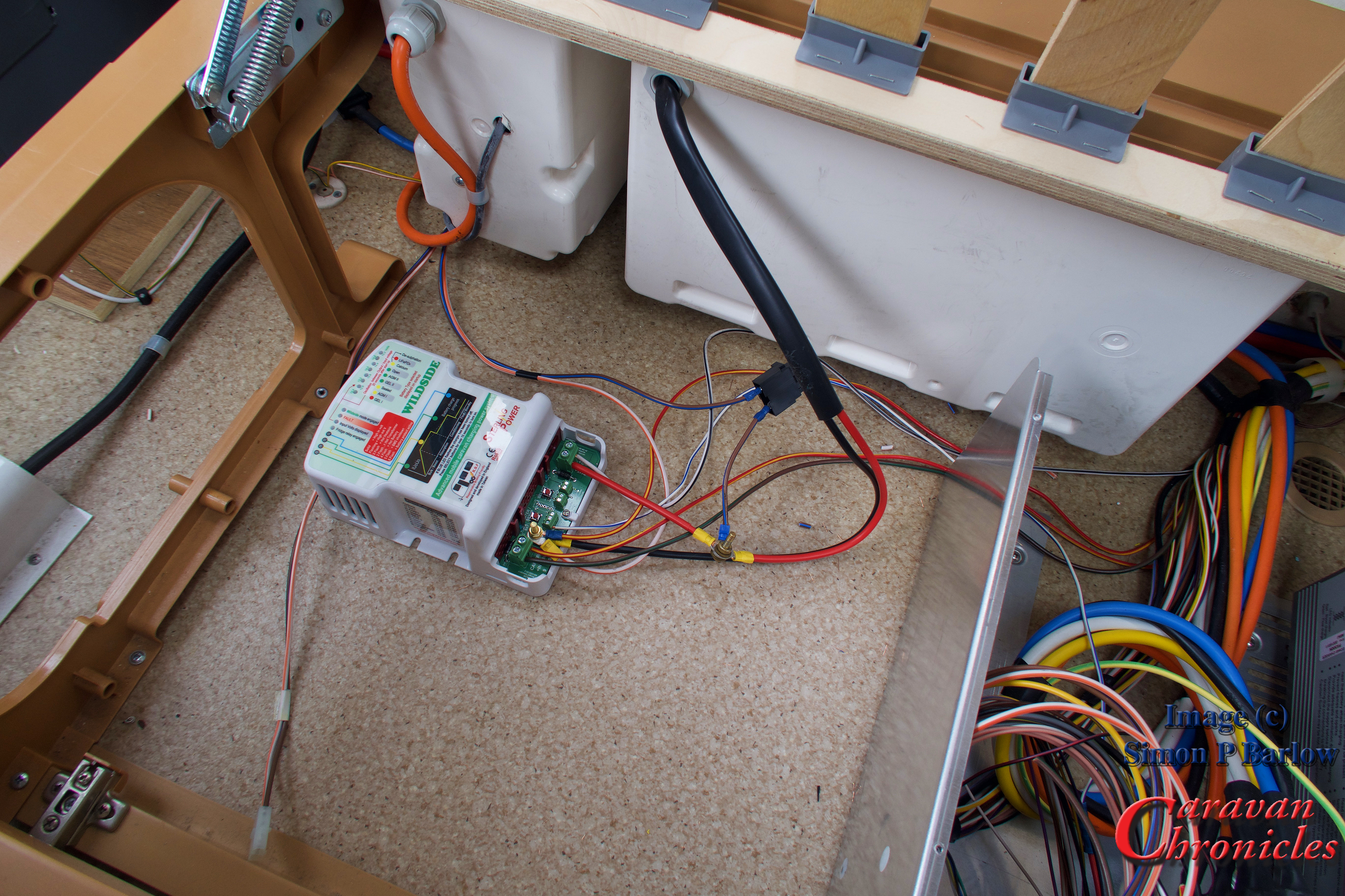
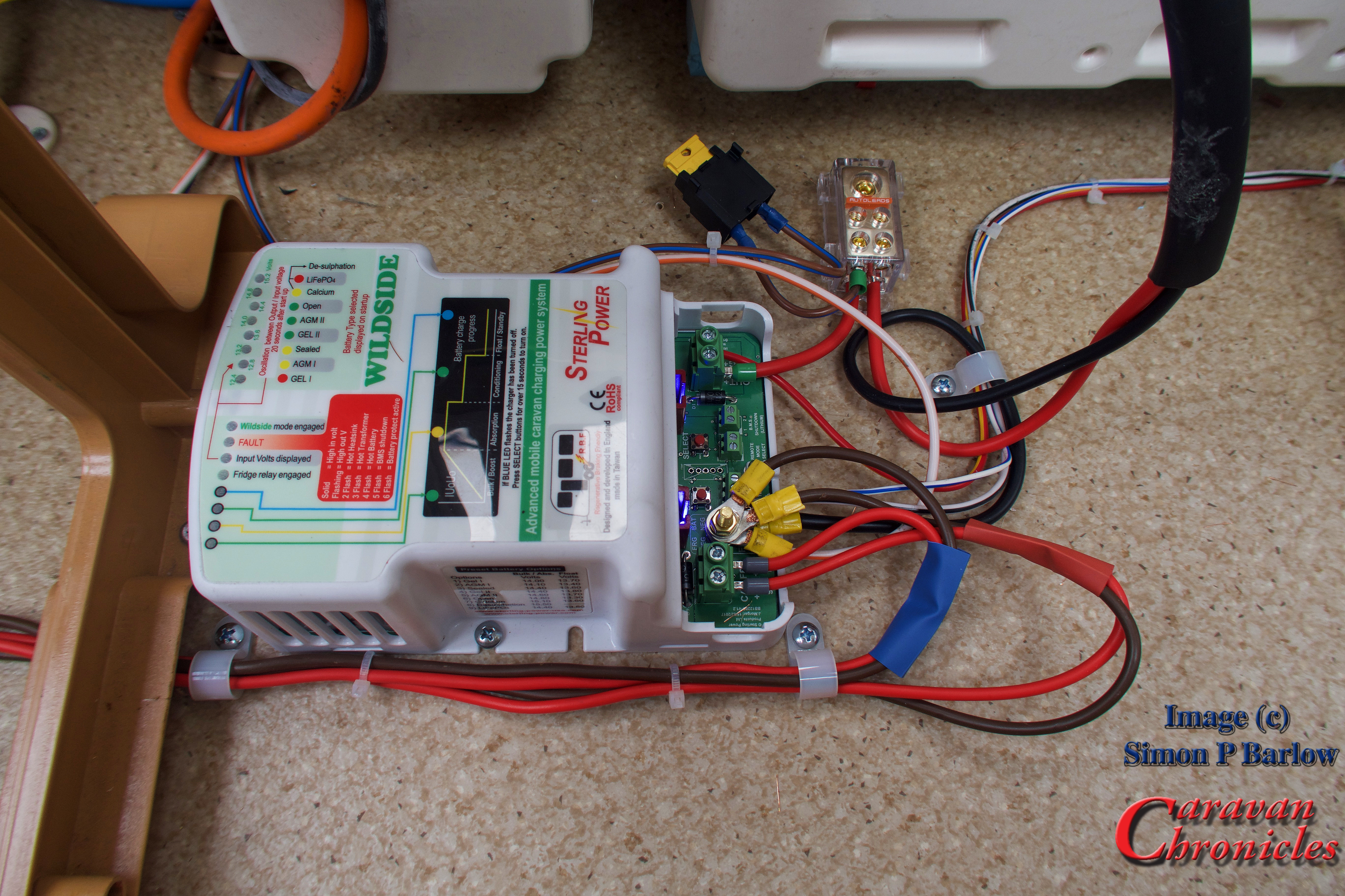
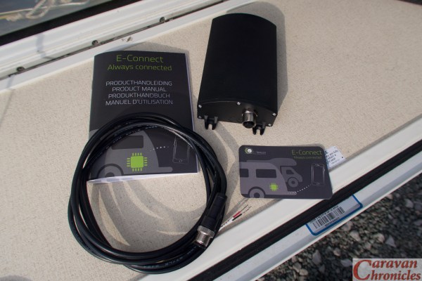
The actual unit is about 120mm long by 80mm wide and 40mm high with a good quality power connector at one end.

In the box is the main unit, 1.5 metre long power lead, instruction manual and a card with a QR Code on it.

You get a QR code with each of the modules, and set of instructions, don’t lose the cars with the QR codes on them! (more about these later)

IMG_1401

Installing the unit is serious easy. You just hook up the power lead to a 12 volt supply. I opted to connected to a switched supply sort came on whenever the caravan master switch was on. This would mean it would be active when towing.

IMG_0855

Once you have powered up the main unit, go to the website e-trailer.nl/app and follow the link for your phone. In the case of my iPhone it took me to the App Store were I could download the app. Once downloaded launch the app and follow the on-screen instructions to register. I was a bit surprised it asked for my postcode and house number, but I guess this is how they register the unit to you for warranty etc.

Once you have created your account in the app and logged in… well remember that card with the QR code on it, simply scan the code and it pairs the app with the unit you have just installed.IMG_0861

You are done! It’s that easy. Now to add the modules. The first one I added was the temperature module. You get a small puck shaped device and following the on-screen prompt, scanned the QR code.

IMG_1408

Done… a quick scan and now I have the temperature reading. For each module you can set lower and upper limits and the type of alarm… visual notification, vibrate, sound. From reading the instructions you could put this sensor in the fridge so when you are driving along you can keep an eye on the fridge temperature to make sure your wine or beer is perfectly chilled when you arrive. From what I understand you can add additional temperature sensors so you can check what the temperature is in the caravan at the same time.

IMG_0859

Next was the voltage sensor so you can keep an eye on the battery voltage. Again it was a quick scan of the QR code and I could see instantly what the battery voltage is and its relative state of charge. (I have yet to check how accurate this is).

IMG_0858

Again, it is easy to set the limits, just tap the two cogs in the bottom left corner….

IMG_0857

… And you can adjust the upper and lower alarm voltages. This is really useful as you can correctly set it for flooded call, AGM or lithium batteries.

Want to know if you have left your roof light open or TV aerial up… or even if your fridge door is open? There’s a module for that… The E Switch.

IMG_1409

In the E-switch module you get two magnetic contact switches that come with 3M pads so you can stick them almost anywhere. Again adding them is a simple scan of the QR code and follow the instructions on-screen. I edited the text for the first switch so I know it is the TV Aerial.

IMG_0860

If one of the switches is open, on the home screen you see that the padlock is orange, close the switch and the padlock closes and the icon turns green.

IMG_0863
IMG_0862

So what else can it do? Well I also have the tyre pressure monitor module. You get two pressure sensors to attach to the tyre valve stems. The sensors are the type that you can change the battery, which I much prefer, as opposed to the sealed type. I’ve not installed the TPMS module yet as I’m still testing out other TPMS systems on the Amarok and caravan but no doubt it will be an easy install… by just scanning the QR code!

IMG_1411

The last little trick that is has is it is an extreme accurate caravan levelling aid. Again a quick scan of the QR code gets this up and running and follow the on-screen instructions to determine your level point and it becomes easy to level next time you pitch.

OK so what did I think about it?

Well it was super easy to install. It was also super easy to add each module. I like the fact that when you hit up to set off you can check the battery voltage and see if it is charging. You can make sure what ever you have attached the magnetic contacts to you can see if they are in the correct position (i.e. closed, lowered etc.) and you can check the fridge or caravan temperature and tyre pressure.

While driving you can keep an eye on things like your caravan’s tyres, battery charge and fridge temperature. when you arrive on site, reversing into your pitch you can easily see if the caravan needs levelling side to side using ramps or blocks and when you un-hitch you can adjust the jockey wheel to get perfect levelling front to back.

“We have a problem Huston…..”

Now I do have a problem with it. Come what may I cannot get it to vibrate, notify me or play a sound when  anything goes out of the parameters (switch open, battery voltage low etc. I made sure I had the latest version of the app, I have double checked all the settings within my iPhone but I cannot get a single ‘vurrrrrr’ or ‘ding’ out of it. Admittedly my iPhone is now 2 versions behind the times but if the app installed I’d have expected it to work ok. I’ll continue to work on this one.

Finally…

I think the idea and technology is great behind the product and I really do like it and can see lots of additional applications could be added on in the future.

Why though is it an after market accessory? When you can be paying the best part of £30k for a top end caravan should not this sort of information system be standard? When I hitch up and set off, I’d love to be able to check the battery voltage (and charging current) check the fridge was working, tyre pressures, doors and hatches closed… and it is not beyond the engineering skills of man to be able to have a bulb out detection system for the road lights even…. all fed directly to your phone.

If a manufacturer decided to install such a unit the price point would drop dramatically.. and that’s one of my other niggles. The technology and ease of installation is great, however there is a bit of an ‘ouch’ in the wallet as currently the comfort pack is priced around £380. That’s a lot of nights on site. You can build up the unit by just buying the individual modules though.

Do I want one… “Yes”…. would I buy one…. I’ll just go and have a word with Sue.

The e-Trailer is currently available from Road Pro here.. www.roadpro.co.uk/catalogue/01m-smart-trailer

Share this:

  • Share on X (Opens in new window) X
  • Share on Facebook (Opens in new window) Facebook
  • Share on Tumblr (Opens in new window) Tumblr
  • Share on Pocket (Opens in new window) Pocket
  • Share on Pinterest (Opens in new window) Pinterest
  • Share on Reddit (Opens in new window) Reddit
Like Loading...

Getting All Charged Up – Update 2…

29 Monday Jan 2018

Posted by Simon Barlow in Accessories, Blog updates, Electrical, Gadgets, Maintenance, Modifications, Product Review

≈ 10 Comments

Tags

Accessories, Maintenance, RoadPro, Sterling Power Wildside, Technical

I guess this really is the update to an update (Getting All Charged Up – Update…). We have been living with the Sterling Wildside unit now for about 6 months and a LOT of people have been emailing me asking how we are getting on with it and is it worth it?

IMG_1194
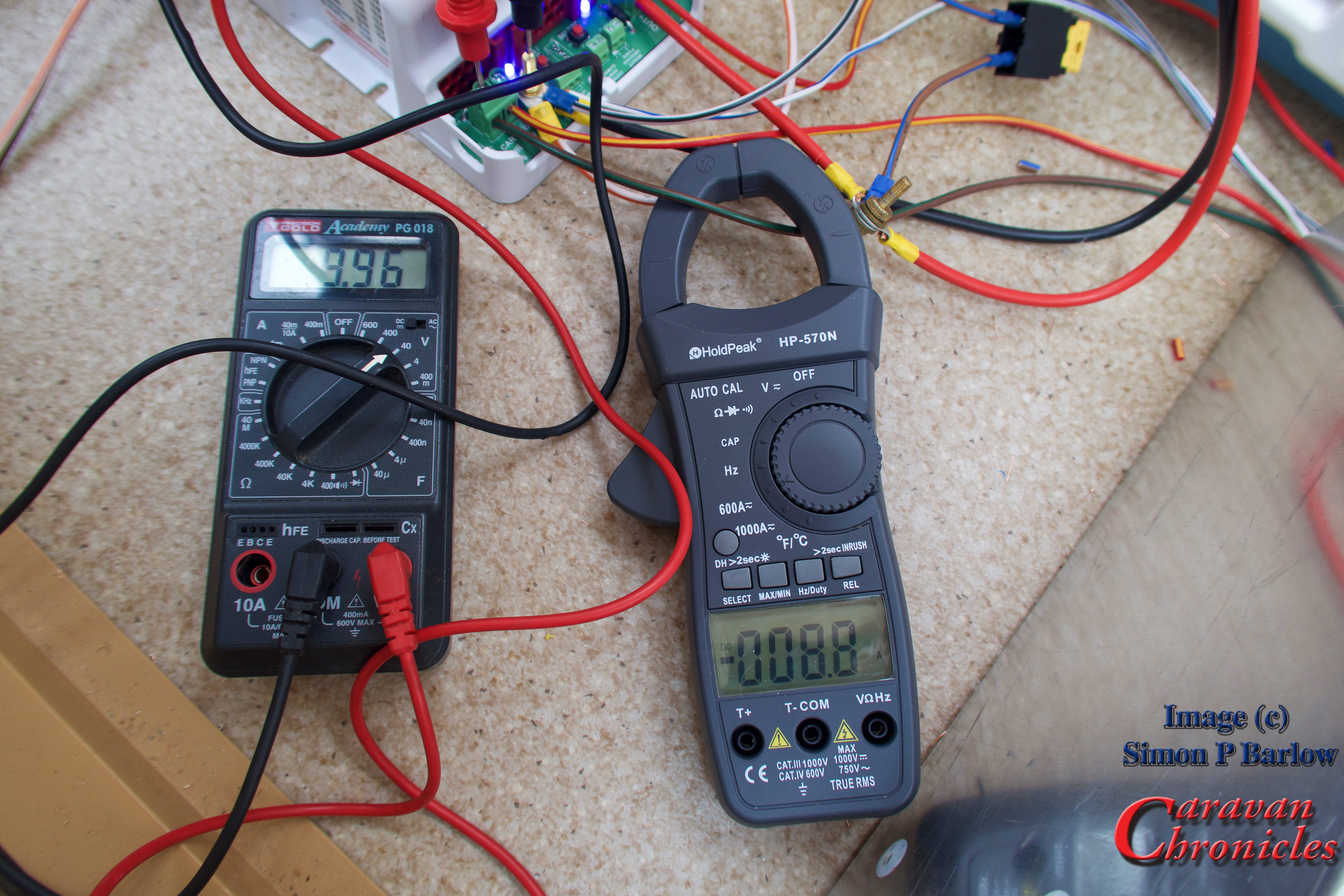
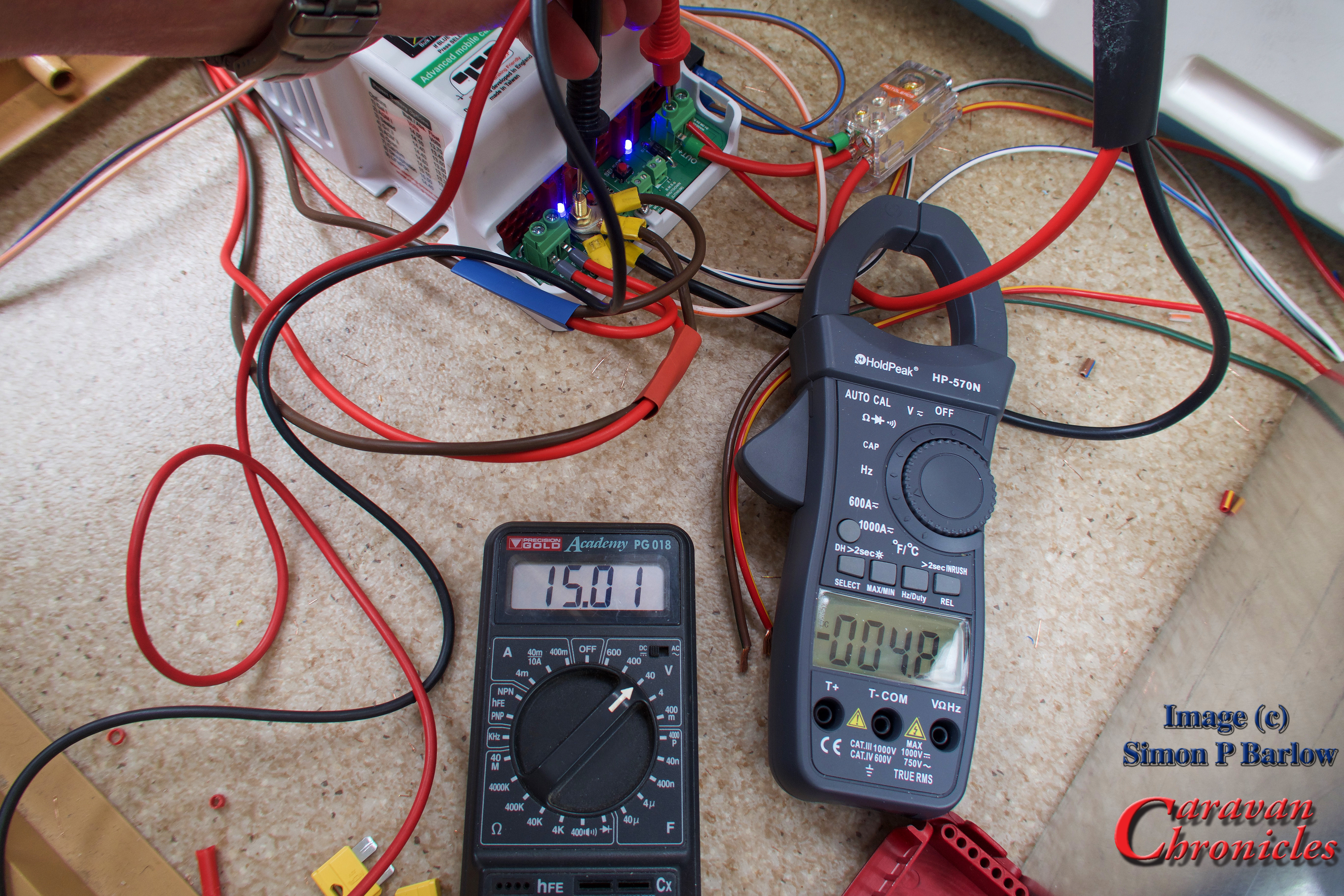
Well I have done quite a bit of testing with my leisure battery in various states of discharge. With it at about 50% I have recorded a charging current of 15.9 Amps which is far greater than I could manage before and due to the fact that the Wildside unit uses the correct charging profile for my battery I’m not concerned that I will be reducing or damaging my leisure batteries life expectancy.

Earlier this month I had an email from David Dent who had successfully installed a Wildside unit in his Bailey Unicorn 3 Cadiz and he seemed pleased with the results so far. Although installing it in a Bailey was a bit more of a challenge. I’m looking forward to checking back with David to see how he is getting on with his unit.

A couple of other people have also emailed me reporting that after installing a Wildside unit that it had solved their problem of having enough stored energy to operate their motor movers. I still wonder if people who have been experiencing problems with their motor movers caused by supposedly bad batteries and have had to replace them is possibly down to the fact their battery was never really receiving a correct or full charge before causing its early demise.

New Tool…

One of the things I want to get to add to my ‘tool box’ in the near future is one of the computerised digital battery testers. At the moment I’m basing a lot of my work on the voltage of the battery and chemistry type. I’d like to be able to improve on this.

Watch This Space…

The other thing I’d also like to be able to do is get a voltage and charge current reading for the leisure battery while we are actually driving. I have been looking at a few – mainly American options for bluetooth remote voltage and current sensors that you can connect up to with your phone. There are a couple of devices that offer a separate display to fit in your vehicle.

However, there is a rather exciting unit that will shortly be coming on the market in this area that might be a bit of a game changer. If you want to know what it is well go and see Andy Harris or one of the guys on the Road Pro stand at the NEC in a couple of weeks time as they, along with the manufacturer will be launching and demonstrating a new product that might just be bringing caravan technology bang up-to-date. I hope to be bringing you a bit more about this soon and maybe an install too!

Final Thoughts….

Is the Wildside unit worth it?  Before I answer this let me just say I am not being paid by anyone for any endorsements of this unit. I was supplied one of the first (pre production?) units as a test and to provide feedback to Sterling Power on how easy it was to install and it’s performance in the real world, which I did. As a result a couple of things were ‘tweaked’ hence mine had to be returned, reprogrammed and reinstalled.

Well I’d say if you have a Euro 6 or even a 5 engine and you want to make sure your battery is looked after then yes. If you want to upgrade to a more advanced battery chemistry, again yes.  If I had to return mine would I go out and buy one? Yes I would.

Is there anything I’d like to see changed? Well if they ever did a Wildside 2.0 I’d like to be able to move the caravan’s own charging system so it was routed through the Wildside unit when on mains hook up to take advantage of the Wildside’s smart charging facility and to allow you to move to more advanced battery chemistry. I guess also adding a solar panel input with built-in MPPT would be a big hit too.

In The Future…

I’m starting to wonder if the way we charge and power caravans needs to take a leap forward. I have had an idea that you could basically split an inverter. One half in the vehicle and the other in the caravan. Imagine a small unit that takes the 12 volt DC from the vehicle and inverts it to 48 volts AC. You then have a lead that connects this across to the caravan and there it is converted back into 12 volts DC.

So whats the difference… all you are doing is what’s already happening? Well using a 2.5 mm cable rated for 25 amps at 48 volts gives you 1200 watts of power. To transfer that much power at 12 volts you would need 100 Amps. Keeping it at 48 volts will mean the system is still in the ELV range for safety. (Use 4mm cable and this could be 1680 watts of power which would be equivalent to 140 Amps at 12 volts)

Being able to transfer that sort of energy would allow you to forget LPG cylinders and put 1000 Ah of lithium cells in the caravan with a 240 volt inverter and power everything. Just a thought that I’m throwing out there.

Share this:

  • Share on X (Opens in new window) X
  • Share on Facebook (Opens in new window) Facebook
  • Share on Tumblr (Opens in new window) Tumblr
  • Share on Pocket (Opens in new window) Pocket
  • Share on Pinterest (Opens in new window) Pinterest
  • Share on Reddit (Opens in new window) Reddit
Like Loading...

Is A Euro 6 Engine Killing Your Leisure Battery?…

21 Friday Jul 2017

Posted by Simon Barlow in Accessories, Amarok, Caravan Electrical Fault Finding, Caravan Electrics, Electrical, Maintenance, Modifications, Off Grid, Technical, Tow Vehicle, VW Amarok

≈ 83 Comments

Tags

Caravan Electrics, Euro 6 Engines, Maintenance, Modifications, Sterling Power Wildside

OK… so that title was a bit dramatic! However here’s the thing… I don’t think everything is peachy with Euro 6 engines and charging leisure batteries.

If you are a regular reader, you know I have recently installed one of Sterling Power’s Wildside units (and so far I’m super happy with it!) but I did get an email from someone who had read all my postings about it and asked me if it might cure his problem. Here’s the gist of his email….

Note: I have edited this down a bit…. and withheld the name of the person and vehicle.

“I have recently changed my car to a new 2017 xxxxxxxxxxxx and after several trips with it, on arriving home there is never enough charge in the motor mover to manoeuvre our caravan up our drive (which is on an incline) and park the caravan round the back of the garage. I have to plug the caravan in overnight before I can use the mover.

This only seems to have started happening since we changed to the xxxxxxxxxx. I had the caravan’s battery tested at two garages and they said it is OK and it is only 2 years old. The local caravan service man said he could not find anything wrong with the motor mover.

As we are on mains at the caravan sites we visit for a few days the caravan battery should be fully charged.

Can you help?”

This did have me stumped for a bit. Battery tested OK, no issues with the mover, so what was going on?

While doing some of the prep work for writing about my installation of the Wildside unit, I had spent a few days prodding about our VW Amarok with a multimeter and making a few notes about voltages etc. One thing that I did cotton on to was the cyclic way the vehicles ECU seemed to turn off the alternator…. well I should really say put the alternator into “idle” mode. Now with the caravan attached (pre Wildside unit install) I did notice that  at the start it seemed to take longer for the vehicle’s alternator to go into idle mode but also it seemed to stay in idle for a lot longer and I was in the process of trying to work out why as initially I’d have thought it would have been less as it was running the fridge and charging the leisure battery.

A picture is worth… you know the rest. Here’s one of my excellent drawings!

Euro 6 Problem 01

Right, here we go… The drawing shows a caravan plugged into a tow vehicle that has the engine-turned off. Pin 9 is live as it should be, and the habitation relay in the caravan is effectively off allowing the caravan’s leisure battery to connect and power the caravan’s internal 12 volt systems. As the vehicle engine is off, there is no power on Pin 10 the fridge circuit, as this is controlled by the vehicle’s ECU.

Really this could be any vehicle with any engine. Now let’s have a look at what happens with the engine running…

Euro 6 Problem 02

Pin 10 is live, turned on by the vehicles ECU and this powers the caravans fridge. It also operates the caravan’s habitation relay which now disconnects the leisure battery from the caravan’s 12 volt systems and connects it to Pin 9 so that the vehicle can start to charge it.

Again, this could be any vehicle with any engine. This is how our Land Rover Freelander works with our caravan. All straight forward.

Now lets look at what happens when the Euro 6 engine puts the alternator into “idle” (or Eco mode etc.)

Euro 6 Problem 03

This is where it starts to get interesting. I have taken a few liberties here and made a few assumptions. I have shown the vehicle’s alternator disconnected. In practice the ECU doesn’t disconnect the alternator, it will reduce the field voltage and hence the output, not really disconnecting it but reducing the output to a negligible amount.

The ECU will also monitor the vehicle’s battery voltage and continue to allow the vehicles general electrical system to drain the battery to somewhere around 75% charge (this may be a bit of an arbitrary figure) The ECU will then turn on (or up) the alternators output to recharge the vehicle’s battery to about 80%. Why 80% well it needs the remaining 20% ‘free capacity’ so that when you brake, the excess energy of engine braking (regen) can be dissipated into the vehicle battery. Remember that on a Euro 6 engine the alternator is capable of generating round about 2Kw.

Now at this point it dawned on me that something could be happening here, but the idea was a bit ridiculous…. guys with far more agile grey cells than mine must have worked this out and I dismissed the idea. I must have missed a trick somewhere.

I did a bit more checking. I was using two 17Ah sealed lead acid batteries as my “leisure” battery simply because it was quicker to charge or discharge them than a 120Ah battery. For a fridge load I was using 3 x 50 watt light bulbs and it was all jury rigged to a 13 pin plug so I could just plug it in to either the Freelander or the Amarok to make comparisons. I was using a trusty old AVO 8 meter, a couple of digital multimeters and a clamp meter to measure current so really the whole set up was super sketchy for anything that I could write about. I thought that I must have been missing something somewhere and I actually kind of put it to the back of my mind. I just got on with installing the Wildside unit and writing it up.

“DING” You have mail……

I received an email from Charles Sterling with some very interesting information. During testing he had come across exactly the same issue I was pondering over but had put off further testing. I guess by now you have worked it out. Quite simply you can get current flow in the opposite direction… from caravan leisure battery to vehicle battery. In testing Charles had measured a current of around 6 Amps.

It dawned on me that maybe during my initial testing with my jury rigged set up I hadn’t missed something and the readings I had seen were correct. Both Charles and I quite separately had (in my case ‘stumbled’) on a potential issue with Euro 6 engines and caravans.

Back to the original email earlier. It now made sense. The sender of the email was setting off from their campsite to travel home with a fully charged battery (being on EHU while they were on site) and during the course of the drive home, the vehicles ECU was actually reducing the fully charged leisure battery down to 80% charge as it actually thought that the ‘vehicle’ battery was at 100% charge. Hence when he arrived home, the caravan’s leisure battery didn’t have enough charge to run the motor mover long enough to put the caravan away.

So what does this mean in practice?

Well effectively (give or take a bit of loss due to cabling) the caravan’s leisure battery will only get charged to about 80%. You can now think of the vehicle battery and caravan leisure battery as being one battery bank because that is how the vehicle sees it. If the leisure battery is fully charged its voltage will be higher than the vehicle battery so the vehicle will turn off (or down) the alternator so that the vehicles electrical system can drain it to about 75% ready for accepting the excess energy from regen braking. The caravan’s fridge helps the vehicle by draining the battery bank that bit quicker.

This also answers another question. While I was testing, sometimes I’d plug-in my jury rigged setup and if my two little 17Ah batteries were fully charged I’d get a low current drain indicated on my clamp meter. I’d dismissed this to a certain extent, but now I realise that as my two 17Ah batteries were fully charged and the vehicle battery would be at about 80% charge, there would be enough of a voltage difference for a short while, that the two 17Ah batteries would try to equalise with the vehicle battery by recharging it slightly..

Whats the answer?

Well thankfully I solved my problem when I installed the Wildside unit a few weeks ago.

Finally…

If you have had any electrical issues with a Euro 6 engine and towing please drop a comment below. I’ll try to help.

As an aside, I am trying to arrange attending a tow bar installers electrical course with a couple of the OEM electrical equipment manufacturers and one of the approved bodies so I can hopefully increase my knowledge base and widen the number of vehicles I can cover. It’s a bit up-in-the-air at the moment as it would appear its going to cost a small fortune! (Sponsorship deals gratefully received!)

Share this:

  • Share on X (Opens in new window) X
  • Share on Facebook (Opens in new window) Facebook
  • Share on Tumblr (Opens in new window) Tumblr
  • Share on Pocket (Opens in new window) Pocket
  • Share on Pinterest (Opens in new window) Pinterest
  • Share on Reddit (Opens in new window) Reddit
Like Loading...

Getting All Charged Up – Part 3 “The Install”…

30 Tuesday May 2017

Posted by Simon Barlow in Accessories, Boondocking, Caravan Electrical Fault Finding, Caravan Electrics, Caravan Fault Finding, Electrical, General, Modifications, Off Grid, Technical

≈ 16 Comments

Tags

Caravan Electrics, Leisure Battery, Leisure Battery Charging, Maintenance, Sterling Power, Sterling Power Wildside, Technical

There has been a bit of a delay since Part 1 and Part 2 due to Sue having a fall and breaking her arm in three places. This required over three hours of surgery to install enough metalwork and screws to keep a blacksmith happy followed up by a lot of trips back and forth to the hospital. However, on with the install of the Sterling Power Wildside unit. I think that this will be the first ever install of a unit in a caravan.

I printed out copies of the wiring diagrams and loaded up the Amarok with everything  I’d need and set off for the storage site. Arriving at the caravan everything was cleared out to give me some space to work.

IMG_1134

I’d planned to install the unit somewhere close to the Sargent control box as all the connections I’d need could be found here and it was close to the fuse box that connected the lead from the 13 pin plug to the caravan services.

IMG_1136

The fuse connection point for the lead from the 13 pin plug is in our caravan, located right at the front next to the centre chest of draws against the gas locker wall.

IMG_1135

Before starting, I did a quick voltage check on the leisure battery…. 12.81 volts, which isn’t too shabby as we don’t have a solar panel and it had been February 25th when I left the Caravan show at the NEC and the battery was last charged up. Which was   about 13 weeks earlier.

IMG_1139

To gain access to the wiring going into the Sargent unit, I removed the 4 screws holding the top cover on and the lid simply lifted off revealing all the connections and as a bonus, service loops in the cable. This meant it should be possible to install the wild side unit without having to do any cable splicing. I did debate at this stage if it would be possible to install the Wildside unit inside the Sargent box… but I decided as I didn’t know the heat gain of the Wildside unit, it might be prudent not to attempt it.

IMG_1137

The cables inside the Sargent box are basically separated into two looms. One 12 volt and the other 230 volt which keeps things easy and neat. Also the back of the circuit board within the Sargent unit was printed with each of the plug numbers, so doing all the planning paid off as I could simply find the plug number from my diagram and locate the correct cable easily.

I decided I was going to do a pre-install and connect the Wildside unit up and do a few tests, then once I was happy I’d go ahead and do a full more permanent installation.

It was simply now a matter of finding the plug I needed, unplugging it, locating the correct wire, cutting it and terminating it in the Wildside unit.

IMG_1140

I cut the cables about 4 inches away from the circuit board plug. This would give me plenty of length to crimp on a sleeve connector and heat shrink if I needed to remove the Wildside unit. As a backup I have also ordered some replacement pin inserts for the plugs so I could always re-terminate directly into the plug.

The next connections would be the incoming feed from the vehicle. 4 cables, two neutral and one positive fridge supply from pin 10 and one positive charging supply from pin 9.  These arrive from the 13 pin plug via the fuse box mounted on the front wall through two 20 amp fuses and to the Sergeant unit. I had trouble identifying the cables as the colours were not as indicated in the manufacturers drawings. So to double check I removed the fuse box to gain access to the 13 core cable where it terminates.

IMG_1141

It was easy enough now to trace the correct cables and confirm with my multimeter. So all the connections now made, albeit temporary, I could install the 20 Amp main battery fuse and make sure the Wildside unit powered up OK.

Don’t worry about the brass bolt holding together the three cables, it was so I could easily get a clamp meter on the cables to take current readings.

IMG_1142

It started up without any problems and so I could connect up the 13 pin plug to the Amarok and start the engine and take a few measurements.

I checked the vehicles voltage and it was sat at 14.5 with run/stop disabled and the engine ticking over. OK how come I had a voltage of 14.5 volts in the vehicle with a Euro 6 engine ticking over? Well the Wildside unit basically makes the vehicle’s ECU think that the vehicle battery requires charging (remember an Euro 6 engine cranking battery will only ever be charged to 80% of its capacity so that regen will always work).

The first reading I checked was the leisure battery incoming link. I had a reading of 9.96 volts and a current of 8.8 amps. That was quite a big voltage drop.

IMG_1143

I moved on to test the incoming fridge circuit. This was showing 9.99 volts and a current of 13.3 amps. I had a big voltage drop somewhere. I checked the voltage at the point the 13 core cable terminates and got a reading of 12.75 volts. somewhere between the incoming cable and the termination on the Wildside unit I was getting a  big voltage drop.

IMG_1144

Continuing with taking some readings, I checked the fridge output and it was stable at 14.35 volts, 9.9 amps.

IMG_1145

A problem with the fridge…

On the original caravan wiring diagram it showed the fridge heating element connected with just two wires and on the face of it this looked simple enough. However when I first connected the fridge and powered up, the fridge came up with error code 10 – no power. There was definitely a supply voltage there and it was indicating a current draw of just under 10 amps. I wondered if the voltage detect circuit was polarity sensitive so swiped the connections round and this cleared the error code. So double check the polarity of the connection if you get an error code 10 don’t assume there is a connection fault.

Thinking cap on…

I decided to stop at this point. Unless I could eliminate that volt drop between the incoming cable and the Wildside unit it was pointless taking any further readings.

The next thing to do would be to eliminate the existing wiring for the leisure battery charging circuit and fridge circuit between where the incoming cable from the 13 pin plug terminated and the Wildside unit. I decided to replace the existing caravan wiring with some 2.5mm² cable.

First job was to terminate all the previously terminated cables on the Wildside unit correctly with the correct size ferrule crimped on. When ever you terminate a stranded cable in  a terminal block that compresses the wire, you should first crimp a ferrule on to the cable to ensure a secure connection.

IMG_1148

Next I installed the four new 2.5mm² cables from the 13 core cable to the Wildside unit. I opted to use straight through sleeve crimp connectors to join to the cable coming from the 13 pin plug. I kept the length as short a possible – about 900mm, which resulted in not the best cable route option but I wanted to minimise voltage drop. (remember, the more current you draw through a cable and the longer the cable the bigger the voltage drop!)

All that done, and the correct terminal block installed for the battery positive lead rather than my brass bolt, I powered up everything and hooked up the Amarok and started the engine once again. With the engine running the vehicle was showing 14.7 volts and I was now getting 14.1 volts on the incoming charing circuit with a current draw of 8.2 amps. Note: the clamp meter in the picture is actually showing the charging current for the leisure battery… 5.0 amps.

IMG_1149

Checking the incoming fridge feed I was reading 14.2 volts and a current of 8.6 amps. Which was a vast improvement over my previous readings. (Note: the clamp meter in the picture below is still showing the battery charging current)

IMG_1150

The battery charging voltage was showing 15.01 and 4.8 amps which meant I was at least charing the battery with just the engine on idle.

IMG_1152

Doing a little maths – I was pulling 8.2 Amps via the leisure battery charging circuit and 8.6 Amps via the fridge circuit giving a total of 16.8 Amps. I was supplying 9.9 Amps to the fridge and 5.0 Amps to the battery. A total of 14.9 Amps. The difference would be due to the losses due to stepping up the voltage being supplied by the vehicle to the output voltages of the Wildside unit. In terms of watts – the vehicle was supplying 237.74 watts and the wild side units was outputting 224.49 watts.

This did make me think. As the fridge was now consuming 149.49 watts (its rated at 150 watts) so it in theory should be at it’s max efficiency… did it need to be on all the time? Could the fridge be switched on a duty cycle of say…on for 75% and off for 25%? This would then increase the ability to put more back into the leisure battery, especially useful on short runs.

Speaking to Charles Sterling, I know this unit has been rated on the conservative side and in theory 20 amps can be pulled from each circuit. This would give around 560 watts of power… and in theory about 400 watts available for charging the leisure battery. Will that damage your vehicle? Well as most Euro 6 engines are fitted with 2Kw alternators, there is still plenty of power available.

Finishing up

It was now a matter of tidying up my mess and installing some cable ‘p’ clips to secure everything to the floor. The two sleeves on the cables that come from the 13 core cable are there so I can identify each circuit. Red for leisure battery charging and blue for fridge circuit.

IMG_1157

The yellow fuse you can see is the leisure battery fuse. It’s rated at 20 amps and is in circuit between the leisure battery and the caravan services, so pull that fuse and the caravan will be isolated from the 12 volt system. I’ll probably replace that with a circuit breaker in the near future.

IMG_1156

IMG_1161

A couple of things I thought about while doing this install.

The Sargent control box is a lot of wasted space. I recon that it should have been shrunk down to ¼ of it’s current size and probably relocated to somewhere else… maybe under the draw unit at the front of the caravan.

The incoming fuse connection panel too seemed a little flimsy. All it consisted of was a circuit board with multi plug connectors on one side and spade connection soldered on the other for the blades of the fuses to slide into. Some of the soldering looked ‘dry’ and I wondered if this was causing some of the volt drop I was experiencing… that coupled with the multi-plug connections in the loom. I know it makes the build of the caravan easier on a production line and you only need semi skilled labour to install but hey sometimes things like this matter.

Its obvious that caravan wiring is done down to a cost and the minimum standard required. I would have liked to seen some slightly heavier gauge cable for some of the connections. It amazed me that the leads that connect to the battery are 6mm² but drop down to 2.5mm² once outside the battery box and the connection between the two is just a simple male/female spade connection.

The other thing that struck me was how inefficiently the plumbing was done. I’d never really looked at it before, but casting my eye over it I think I could have laid it out a bit better and saved three push-fit connectors.

Who’s this unit designed for?

Well anyone really that has a Euro 6 engine in their tow vehicle or motorhome (if you have a motorhome you need to look at the BB1230 which is a step up again from this) and cares about maintaining their leisure battery.

If you have a motor mover fitted and use it to get your caravan out from its parking spot before you set off and then find sometimes you don’t have quite enough power to position your caravan on your pitch when you arrive or the reverse… your motor mover always seems to run out of steam trying to put your caravan back in its storage area when you return home, the Wildside unit should make sure you always have a fully charged battery and I’m my opinion is something that should be classed as an essential item.

From a lot of emails I have received it would seem that generally people with motor movers seem to be changing their batteries more frequently. A lot of the time when the motor mover stope working or works erratically the advice from the motor mover manufacturer is “you need a new battery” or” its a problem with your battery”. I”m going to throw this out there… I think it may be down to the batteries never really getting a proper charge and sulphating, radically shortening their life.

Alternatively if you do a lot of “Off Grid” (Boon-docking) camping, this will make sure you maximise the charge in your leisure battery to allow you to get the most from it. Especially if you have a Euro 6 engine.

How easy is it to install?

Planning is the key and a modicum of skill in being able to trace cables and terminate correctly. However a lot is going to depend on your caravan, how it is connected and the quality of the original installation. For me it was quite straight forward but the location of the existing components made it easy. Depending on your particular caravan you may end up having to run some additional cabling. Whatever you do, do not cheap-out on cable termination! Buy the right terminals and a good ratchet style crimp tool and make sure any cable you install is a good quality brand of the correct gauge.

Were there any issues?

Nope, it worked straight out of the box.

What next?

Road test! In a few weeks we are travelling down to Glastonbury which is between a 5 and 6 hour tow and I’ll be taking readings during the trip to see how the battery is being charged and the fridge temp. Just for the pure fun of it….. I’m going to try to make ice cubes in the freezer so we have ice for our drinks when we arrive! I’ll let you know how I get on.

Looking forward.

The biggest problem really is the fridge. A three way absorption fridge is probably the single most inefficient way of chilling anything. Whether its powered from 12 volts, 230 volts or gas. Its far more efficient to use a compressor fridge.

Now a 230 volt compressor fridge is relatively cheap when compared to a three way absorption fridge, great for when you are on hook up, but now imagine being able to run it via an inverter while you are driving or off grid from your battery. As they only run short periods and take less power to run. Coupled with the fact they don’t run continuously like an absorption fridge. It would be possible to do away with a 3 way absorption fridge completely.  As we now have a sensible way of charging batteries, and given the fact the price of modern lithium battery technology is dropping all the time I don’t think technically we are far off making the transition. Its just down to the caravan manufactures…. so don’t hold your breath.

Contact:

Sterling Power

Stuff I used:

You can find links to all the crimp terminations and tools that I used in the Caravan Chronicles Shop


Share this:

  • Share on X (Opens in new window) X
  • Share on Facebook (Opens in new window) Facebook
  • Share on Tumblr (Opens in new window) Tumblr
  • Share on Pocket (Opens in new window) Pocket
  • Share on Pinterest (Opens in new window) Pinterest
  • Share on Reddit (Opens in new window) Reddit
Like Loading...
← Older posts
Newer posts →
Buy Me A Coffee

Blog Stats

  • 45,910,150 hits
Follow Caravan Chronicles on WordPress.com

Follow Caravan Chronicles and receive notifications of new posts by email.

Some previous posts you may like...

My last post….

Many thanks to all my friends. As I write this I’m in the Christi hospital hoping to go home in a few days. I was told about a week ago that I had about 3 months to live and should start preparing my affairs. Which Sue and I are trying to do. I have some…

A Bit Of A Tour…

Well not really a tour, only two locations. The first leg was down from Manchester to Glastonbury and a stay at The Old Oaks. We first went there in 2012 and had five or six more visits in the next four years. So it had been quite a while really. We were located in the…

What’s The Question I Get Asked a Lot?

“What’s in your toolbox when travelling?” Tricky one… I don’t have a tool box anymore. I recently started mooching around the internet for a smaller tool box… or rather a tool bag. I used to use up until a few months ago a Stanley Tool Bag. It was lighter than a tool box, I could…

#Tourfest North West

Tourfest North west was our first time attending anything like a gathering of bloggers, vloggers and the generally like minded. It was organised by The Caravan Addys with a little help from others I’m sure as it must be a time consuming task and hard work to bring everything together. We opted to arrive at…

More Jobs Ticked Off…

OK we are still working on a few bits and pieces but the weather on Friday and Saturday was ideal for cleaning the outside of the 5th Wheel. So while Sue made a start on the cleaning of the nose cap, I finished the first stage of the water pump relocation project and upgraded the…

A Few More Jobs Ticked Off The List…

Like any project, ticking the small stuff off a list is the way to move forward even if it seems like sometimes you have ground to a halt. A bit lacking on photos…. I’m temporarily unsure of their location… pilot speak for I’ve lost them! I’ll correct that in due course. I built a new…

A Few Little Jobs Done…

It seems such a long time since I posted anything. Last time out with the Dreamseeker I noticed that the charging voltage when we were hooked up to the truck was only about 12.1 to 12.3 volts as measured in the Dreamseeker battery box. I know that the VW Amarok puts out 14.6 to 14.8…

Happy New Year…

Happy New Year to everyone, I hope you have a great touring year ahead. I’d like to take this opportunity to give you a bit of an update on my personal circumstances and a look forward to a couple of projects I’m planning to kick off our year. First… … A HUGE thank-you yo everyone…

Sutton-on-Sea In September

Just like to say a huge thank you to so many people that have commented or emailed me over my last post. It has cheered me up no end…. it really has. Enough to rattle this post off! We recently went back to Cherry Tree Springs at Sutton on Sea for an 7 day break.…

This Might Be My Last Post…

Not clickbait…. Three weeks ago Sue and I were cycling between 8 and 10 miles each morning to get a morning coffee. Arrived back home and…. well time stopped. I had received notice that my test sample for Bowel Cancer screening had come back positive. Two days later I underwent a colonoscopy procedure which didn’t…

Something went wrong. Please refresh the page and/or try again.

  1. Dave Hart's avatar
    Dave Hart on How to: Connect two batteries in parallelAugust 27, 2024

    brilliant and so well explained! Thank you, love your work!!

  2. Simon Barlow's avatar
    Simon Barlow on Caravan Road Lights – Basic Fault FindingAugust 25, 2024

    Please look at my very last post on the blog

  3. Martin's avatar
    Martin on Caravan Road Lights – Basic Fault FindingAugust 25, 2024

    martin here caravan lights worked fine for two stop overs I had then hooking up again for my third trip…

  4. Emmy’s Camper Travels's avatar
    Emmy’s Camper Travels on My last post….August 25, 2024

    I’m so sorry. My sincerest sympathies go to you and your wife Sue. Your ideas and advice have been so…

  5. Steve Walsh-Jones's avatar
    Steve Walsh-Jones on My last post….August 22, 2024

    very sorry to hear this. Your posts have been very informative and enlightening providing an in depth view on different…

  6. thetwinaxletouringscouser's avatar
    thetwinaxletouringscouser on My last post….August 22, 2024

    Good heavens above Simon I am ever sorry to hear of such devastating news for both you yourself and Sue.…

  7. Eileen's avatar
    Eileen on My last post….August 22, 2024

    Simon and Sue, thank you both for sharing your passion for caravans with us. The news is extremely sad, our…

  8. Philip Parkes's avatar
    Philip Parkes on My last post….August 22, 2024

    Simon. So sad to read you last post today. Our thoughts are with you and Sue at this time. Whilst…

  9. Philip Parkes's avatar
    Philip Parkes on My last post….August 22, 2024

    Simon. So sad reading your post today. Our thoughts are with you and Sue at this time.

  10. Philip Parkes's avatar
    Philip Parkes on My last post….August 22, 2024

    Simon our thoughts are with you and Sue.

  11. Luke Tarrant's avatar
    Luke Tarrant on My last post….August 22, 2024

    Very sorry to read this and my thoughts are with you both at this time.

  12. Alan Smith's avatar
    Alan Smith on My last post….August 22, 2024

    Dearest Simon. I have never met you, but I feel as though I have some (limited) knowledge of you and…

CaravanChronicles.com Tag’s…

5th Wheel Caravan 13 Pin Plug Accessories AL-KO Avtex Bear Extender Bike Rack Blackpool Blackpool Illuminations blogging Cadac Camping & Caravanning Club Canterbury Caravan Caravan Blog Caravan Club Caravan Electrical Caravan Electrics Caravanning Caravans Caravan Show Caravan Talk Cheltenham Chirk Christmas Market Christmas markets Cleaning design Event City Factory Visit Fiamma France Freelander Glastonbury Glossop Caravans Humor Insync Jonic Bedding Lady Heyes La Tournerie Ferme Leisure Battery Leisure Battery Charging LPG Refilling Maintenance Manchester Caravan & Motorhome Modifications NEC North Western Caravans Ltd OLPRO One Hairy Caravanner Oswestry Oxford Product Review Project Review Safefill Sat Nav Sterling Caravans Sterling Power Wildside Swift Factory Swift Group Swift Talk Technical The Old Oaks Touring Towing Tow Vehicle Trafford Centre travel Travel Trailer Travel Trailers vacation VW Amarok Warwick Racecourse WiFI

Website Powered by WordPress.com.

  • Subscribe Subscribed
    • Caravan Chronicles
    • Join 672 other subscribers
    • Already have a WordPress.com account? Log in now.
    • Caravan Chronicles
    • Subscribe Subscribed
    • Sign up
    • Log in
    • Report this content
    • View site in Reader
    • Manage subscriptions
    • Collapse this bar
 

Loading Comments...
 

    %d