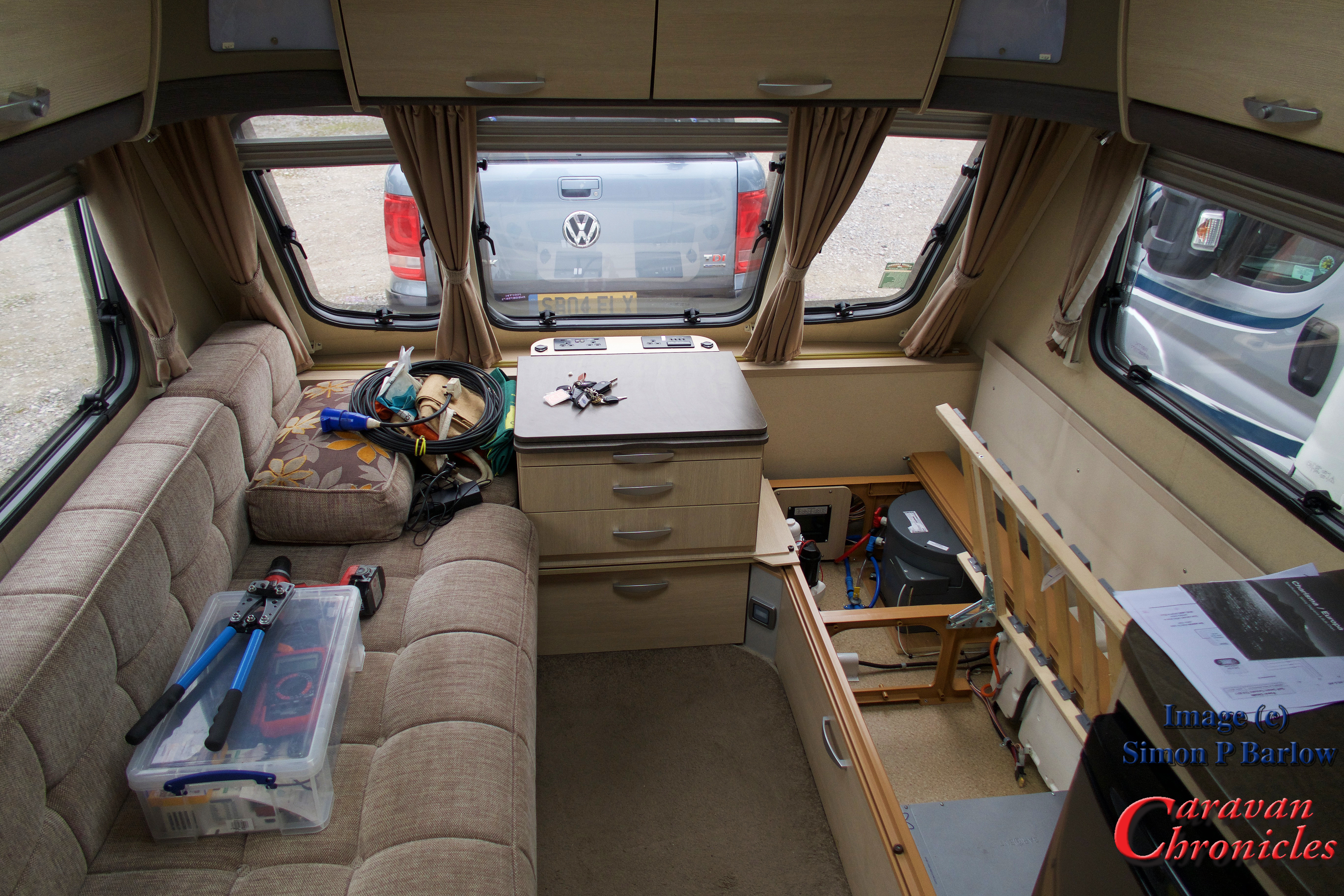
My email box tends to get a wide variety of questions covering all sorts of subjects. The most frequent one is to do with wiring and electrically related problems. Sometimes trying to diagnose issues via email and a few photos is a bit of a challenge, but hey who doesn’t like a challenge! One thing that I do see a lot of is electrical work that is…. well, quite frankly not up to scratch in my opinion. So here is my attempt at a basic guide.

You have to have a plan.
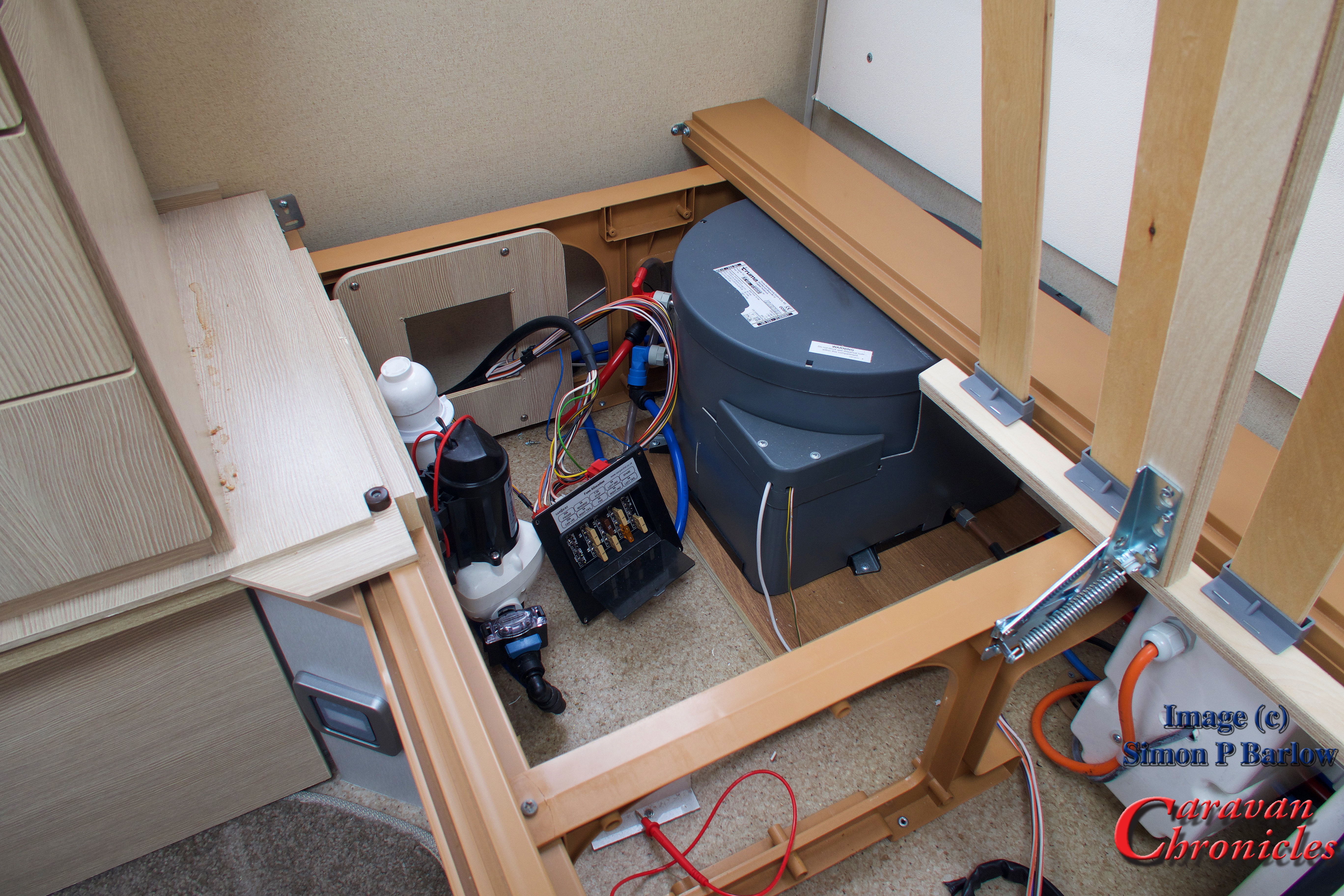
So many projects start by adding one or two things… extra 12 volt outlet here… maybe another light and then something else comes along that needs adding in. Before you know it you have a mess of spaghetti that the local Italian restaurant would be ashamed of. It is all too easy to fall into the trap of adding circuits to existing fuses…. or installing a new fuse and a few weeks later adding another circuit to it as it’s easier than installing another fuse.
You can download these and other drawings from the Electrical Drawings page in the drop down menu under “Document Library”
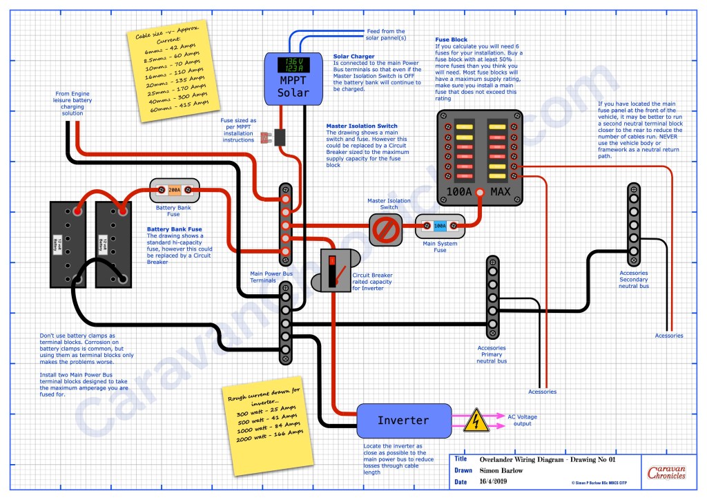
You need to draw out how the major elements are going to connect together – leisure batteries, solar charger, DC to DC charger, inverter and include all the big fuses, buss bars and fuse box. Don’t think about where any of this goes for the moment just get the basic layout and how everything interconnects worked out. It might take a few goes but paper is usually cheaper and less frustrating than sorting out the mess afterwards.
Once you have all that figured out you can start working on the details… just how many fuses will be needed… and what ever number you come up with add half as many again as a minimum. Having a few spare fuse positions that maybe never used is way cheaper than in twelve months time having to install an additional fuse box. A this point you can start adding details…. what size cable is needed for each link, what sort of fuse box do you need.
You can also now start to think about specific facilities you might need. For example, many overlander vehicles will have a button on the dash that when pressed and held down activates a high current relay that links the house batteries to the engine cranking battery. Very handy to have… jump leads are not much use if you are 200Km from the nearest vehicle. If your only trip ‘off road’ however is the muddy car park at the local car boot sale than maybe not a priority.
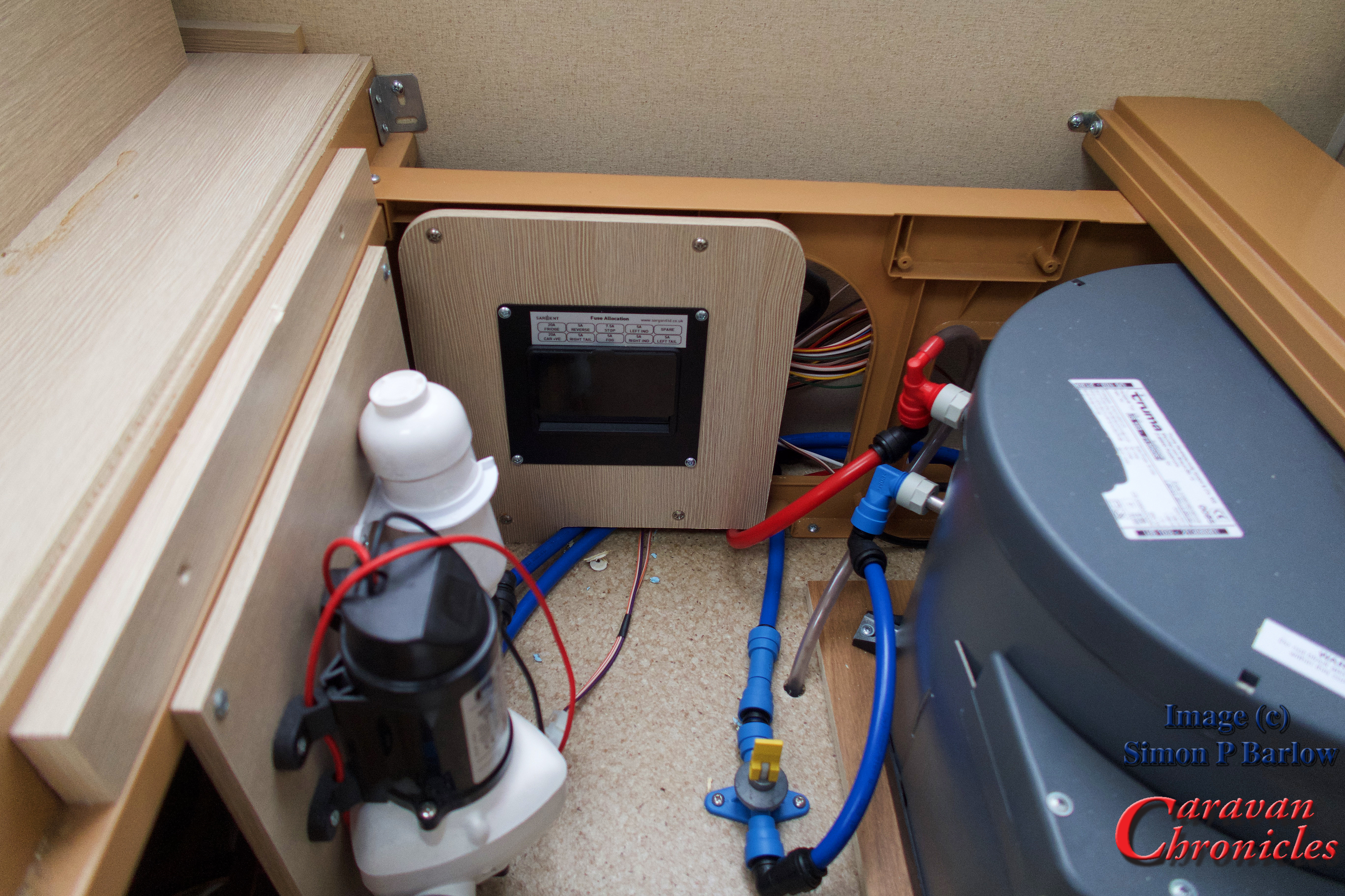
Don’t use the vehicle chassis as a ground.
Modern vehicles are constructed using different materials and quite often panels and sub frames are glued together. Back when virtually all the panels were spot or seam welded steel, using the body and chassis as a ‘ground’…. which really isn’t a ground but the neutral return path… this was acceptable. However now, sections can be glued together and are often sub assemblies of aluminium and other light weight materials bonded together. Just because you see a neutral bonding point (earth terminal) don’t assume this is is capable of being a suitable point to bond the neutral side of a circuit or accessory you are installing. Modern vehicles often have small bonding straps between sections that can carry the current that the vehicle manufacturer rated the bonding point for. Adding additional equipment and accessories might exceed the original design spec.
I did see a spectacular failure due to a 3000W inverter having it’s neutral lead ‘grounded’ in the rear of a vehicle. Running at about 2000W the neutral side was trying to ‘return’ a current of about 170 amps through the body of the vehicle, which lead to serious damage to some of the vehicles wiring and a number of vehicle components… and a ‘repair’ bill of nearly £1500. Putting a riv-nut in a body panel that is mastic bonded to the body is not a suitable negative bonding point!
Additionally a number of vehicle circuits are now negative switching or operation and installing additional equipment or accessories could have unforeseen issues. Always from any accessory or piece of equipment you install, add the neutral return path back to a suitable single common point or buss bar you install for the purpose and connect this directly back to the leisure battery.
Ideally all the ancillary leisure circuits should never rely on any of the vehicle wiring and the negative side of the leisure wiring should only ever connect to the negative side of the leisure battery.
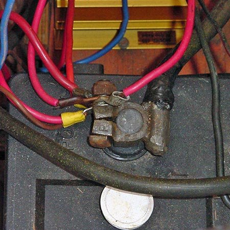
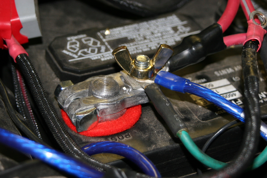
Don’t use battery terminals as a junction post.
Both the leisure battery and engine battery should only have connections that lead to either in the case of the positive terminal a master fuse /circuit breaker and isolator switch. The negative terminal should only have the connection to a master negative terminal point or buss bar.
(image from the Internet)
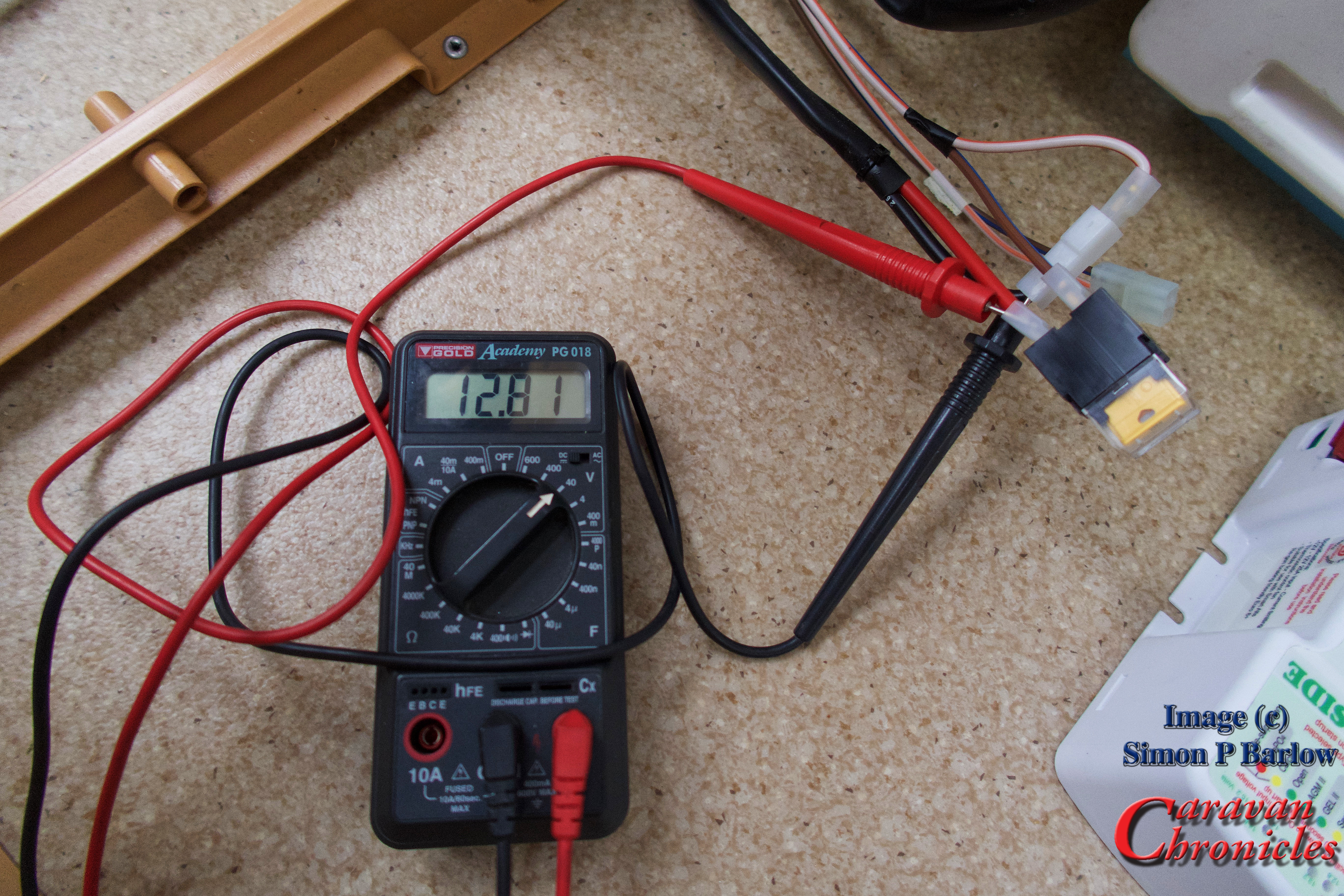
If you want to install any sort of battery monitoring, it is convention to install the shunt on the negative return to the battery between the negative buss bar and the negative battery terminal. If you have multiple circuits terminated on the battery terminal it makes future changes and upgrades, including installing a battery monitor very difficult.

(image from the Internet)
Using the battery terminals as connection points for multiple services also makes fault finding very difficult. Each circuit may or may not have it’s own fuse and it’s difficult to isolate circuits….. plus I’ve had enough sparks flying round when trying to disconnect a battery because someone did not install an isolator to know that it’s only a matter of time before one goes ‘pop’.
(image from the Internet)
Please, just don’t do it.
Have a think on this. If you had to go to an auto electrician to get a fault traced and corrected, they would immediately put at least an hours time on the invoice just to figure out what was going on with all the cables on the battery. Also, If you don’t have a battery master isolator installed, get one installed now. It’s a safety item that must not be missed out. Having the ability to quickly turn off all the leisure circuits in an emergency might just save you from the unthinkable happening.
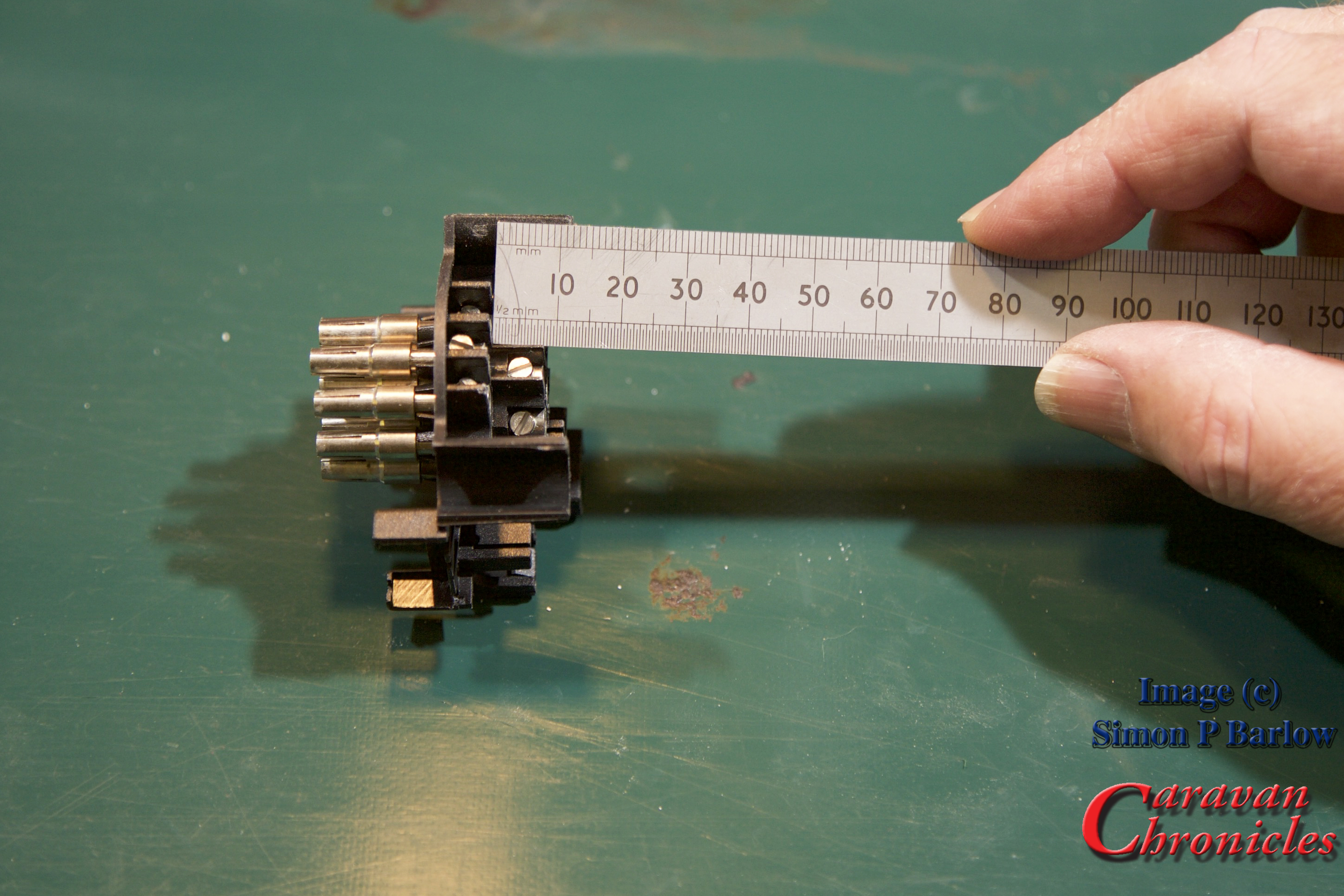
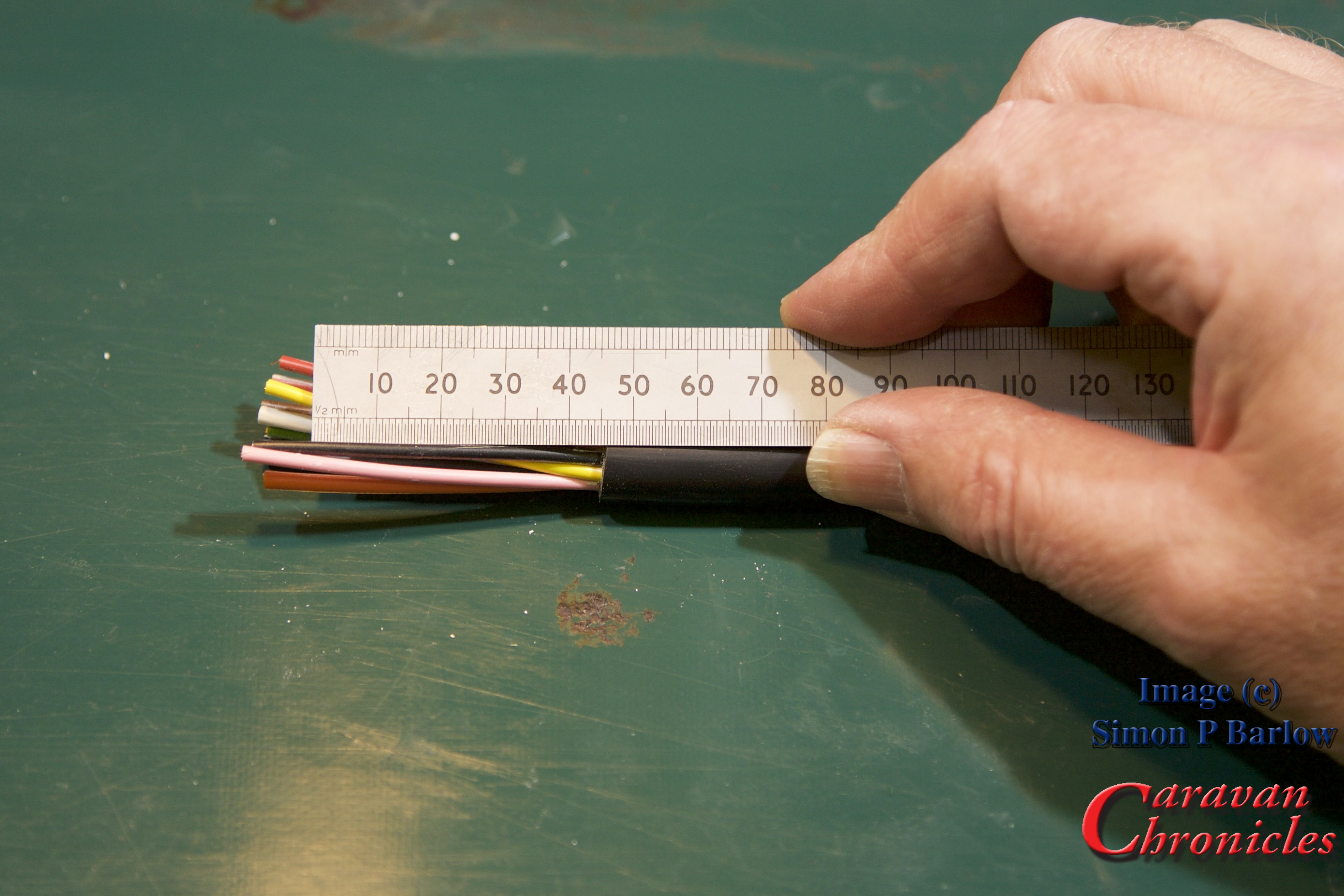
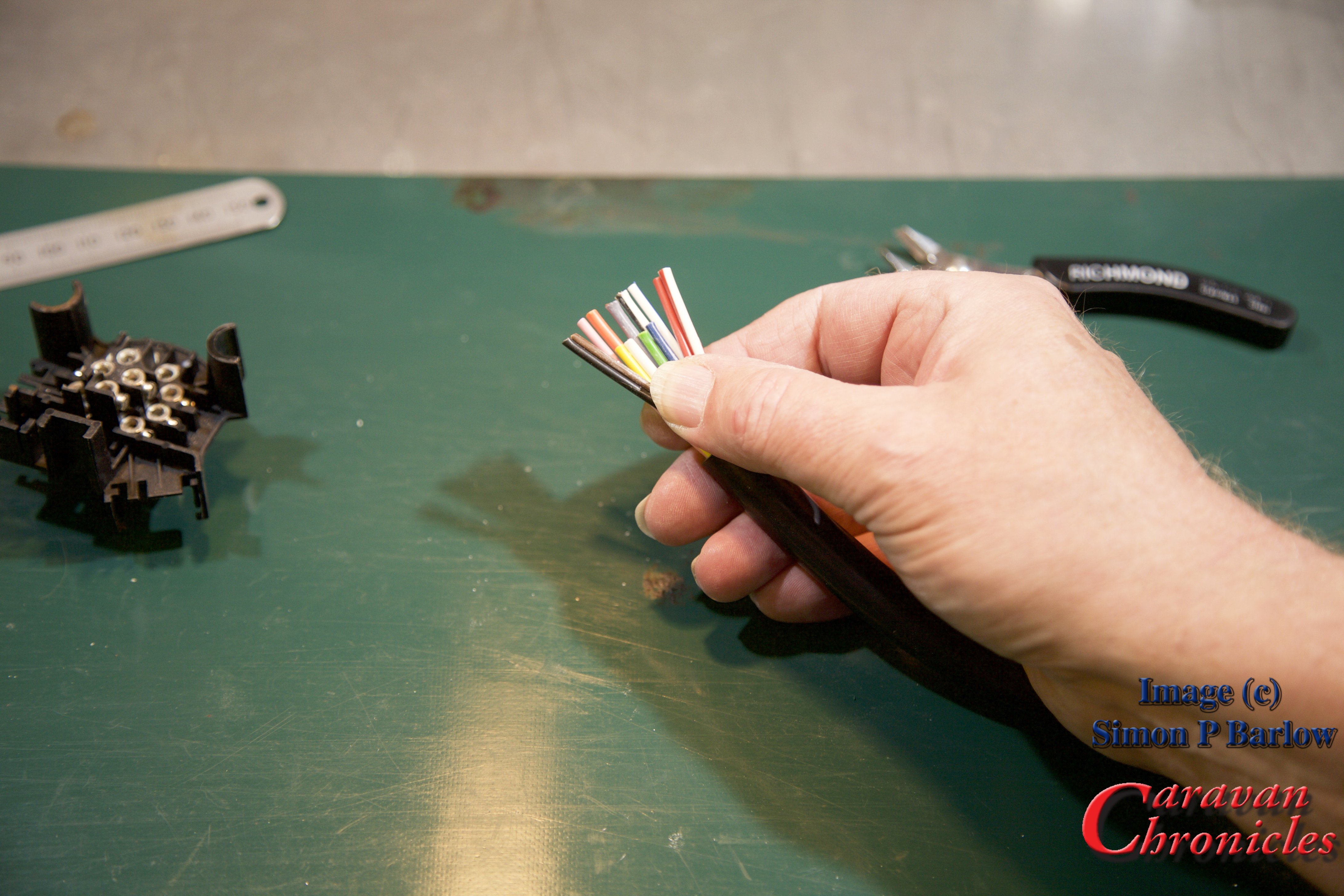
Cable Termination
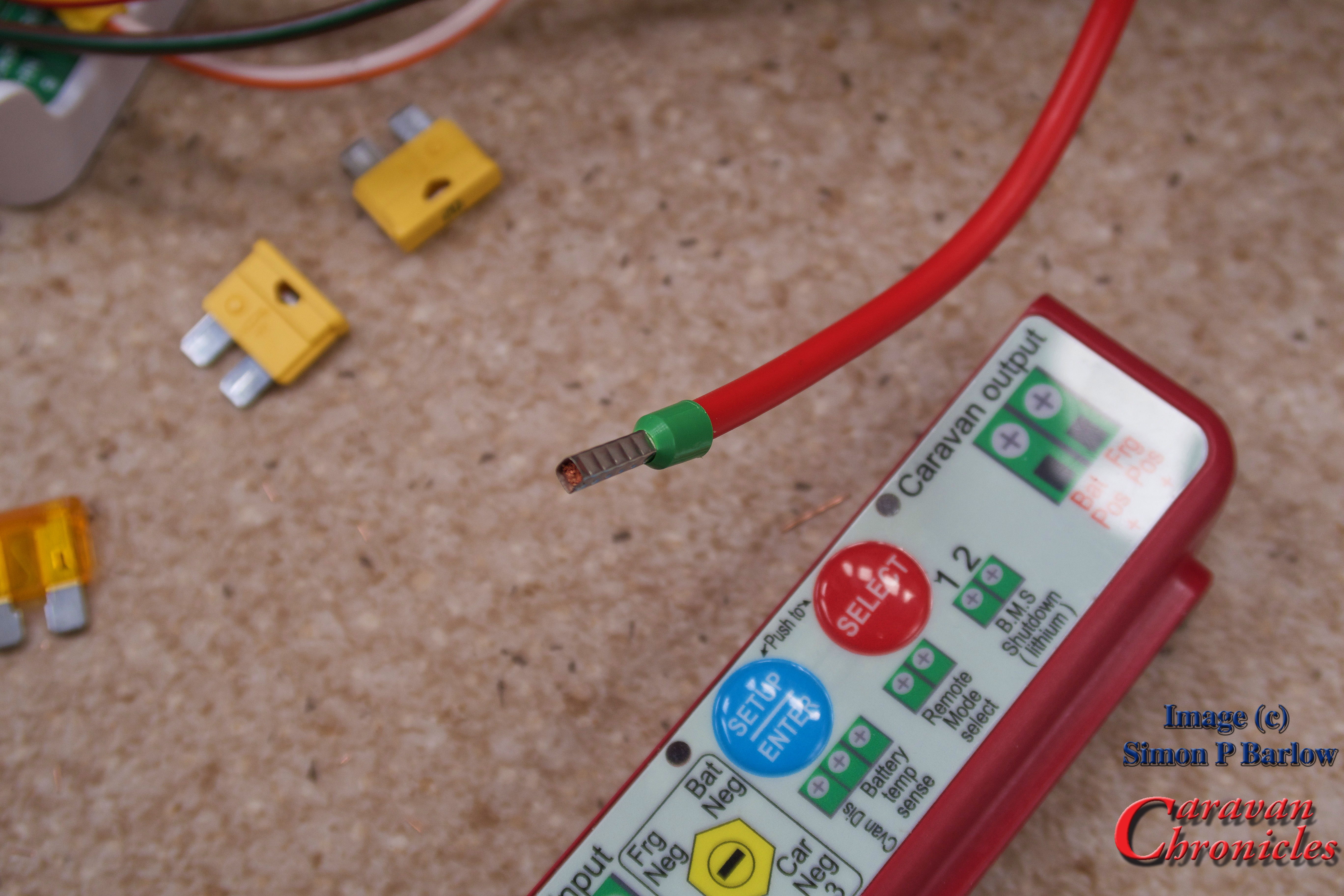
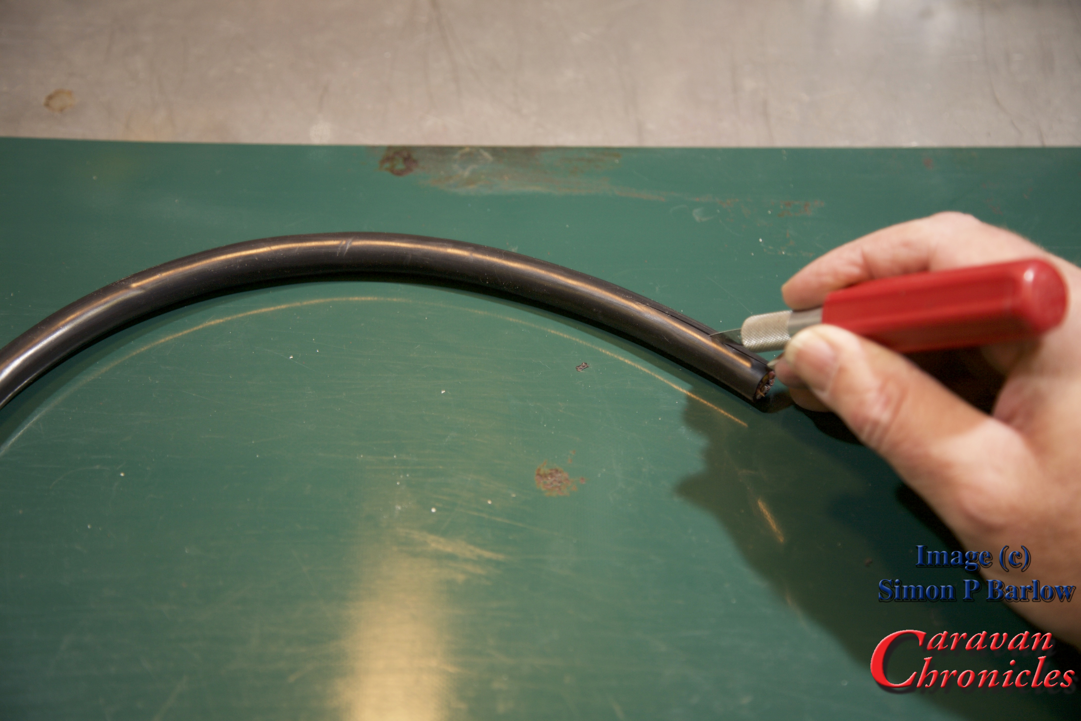
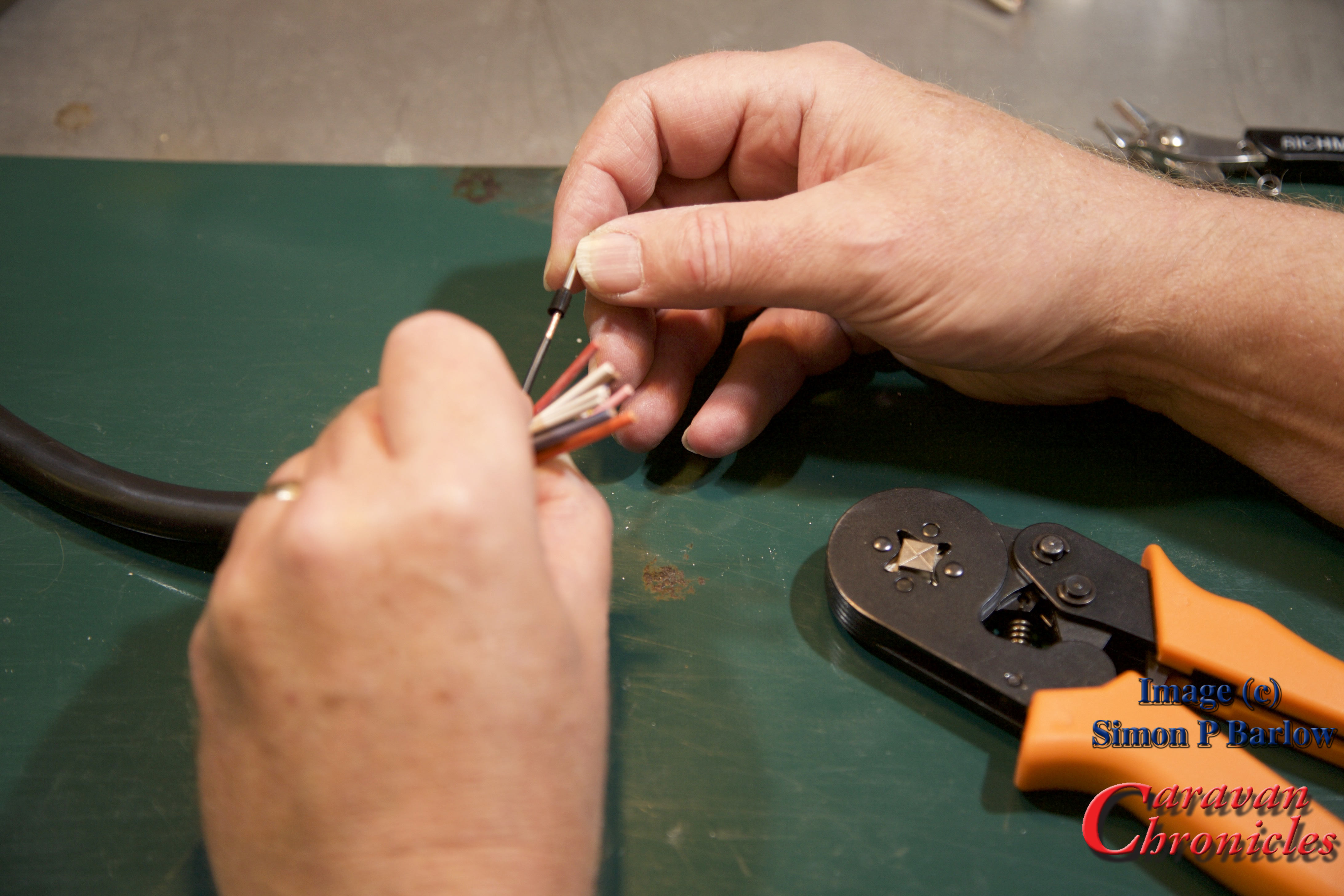
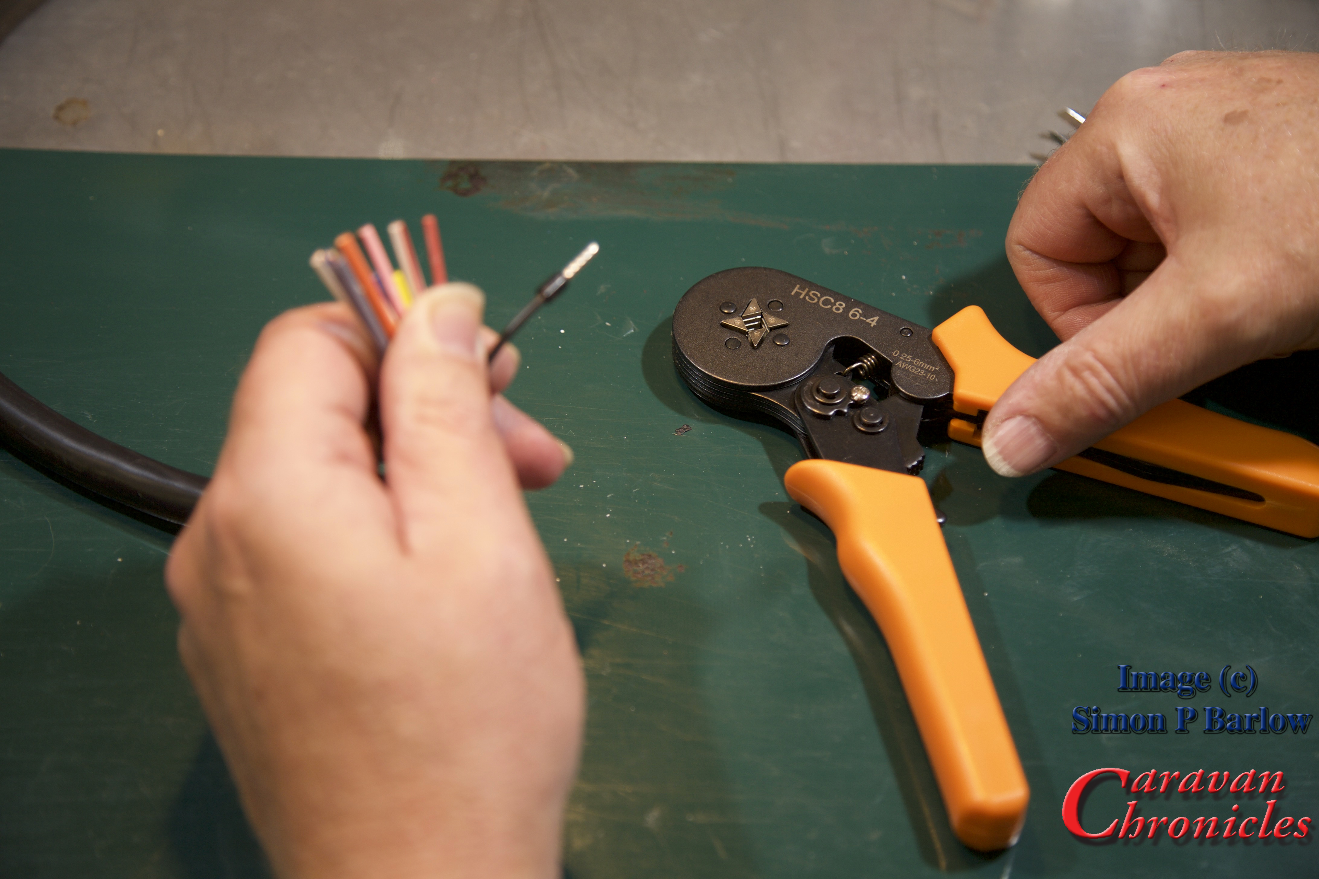
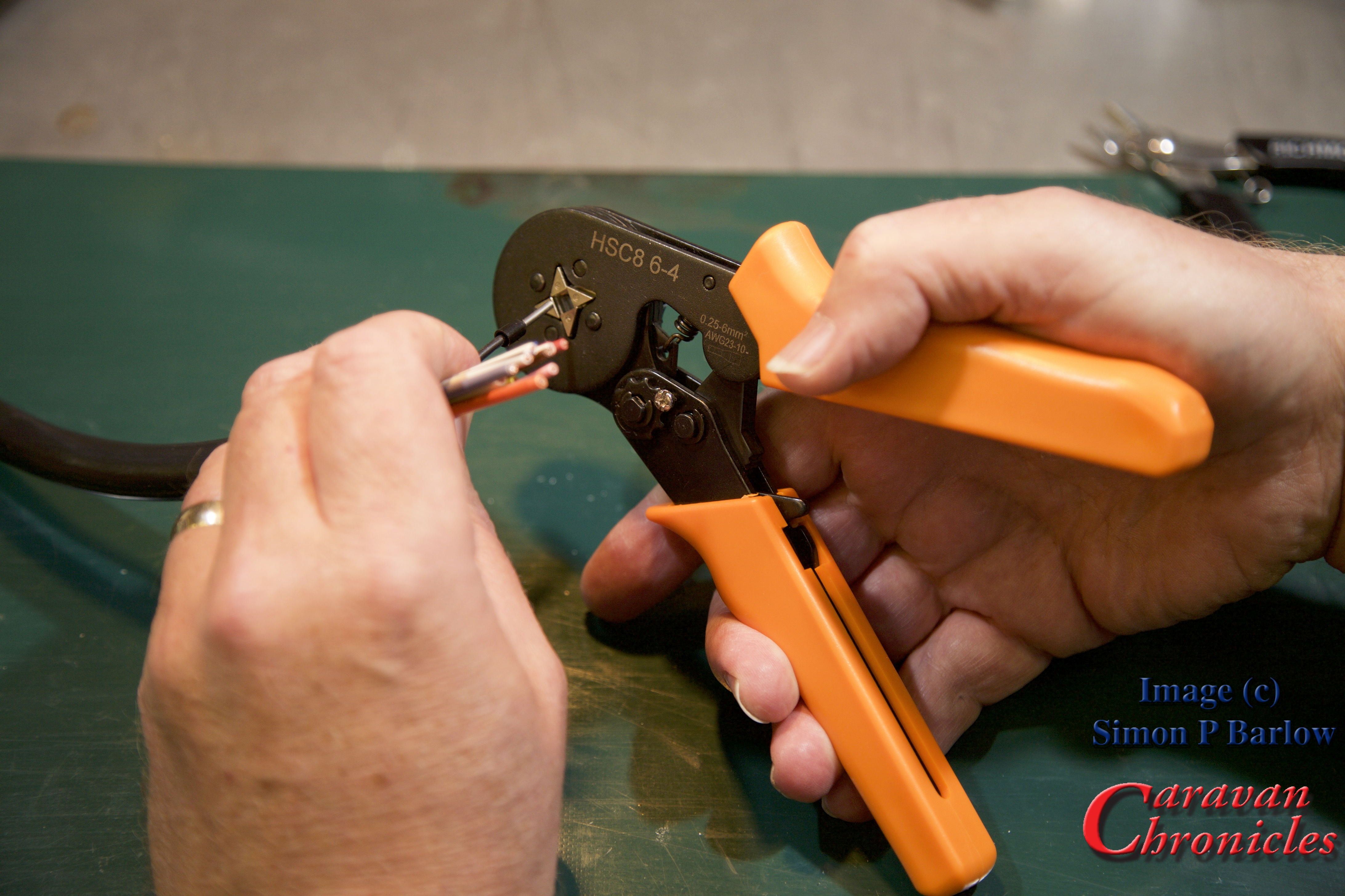
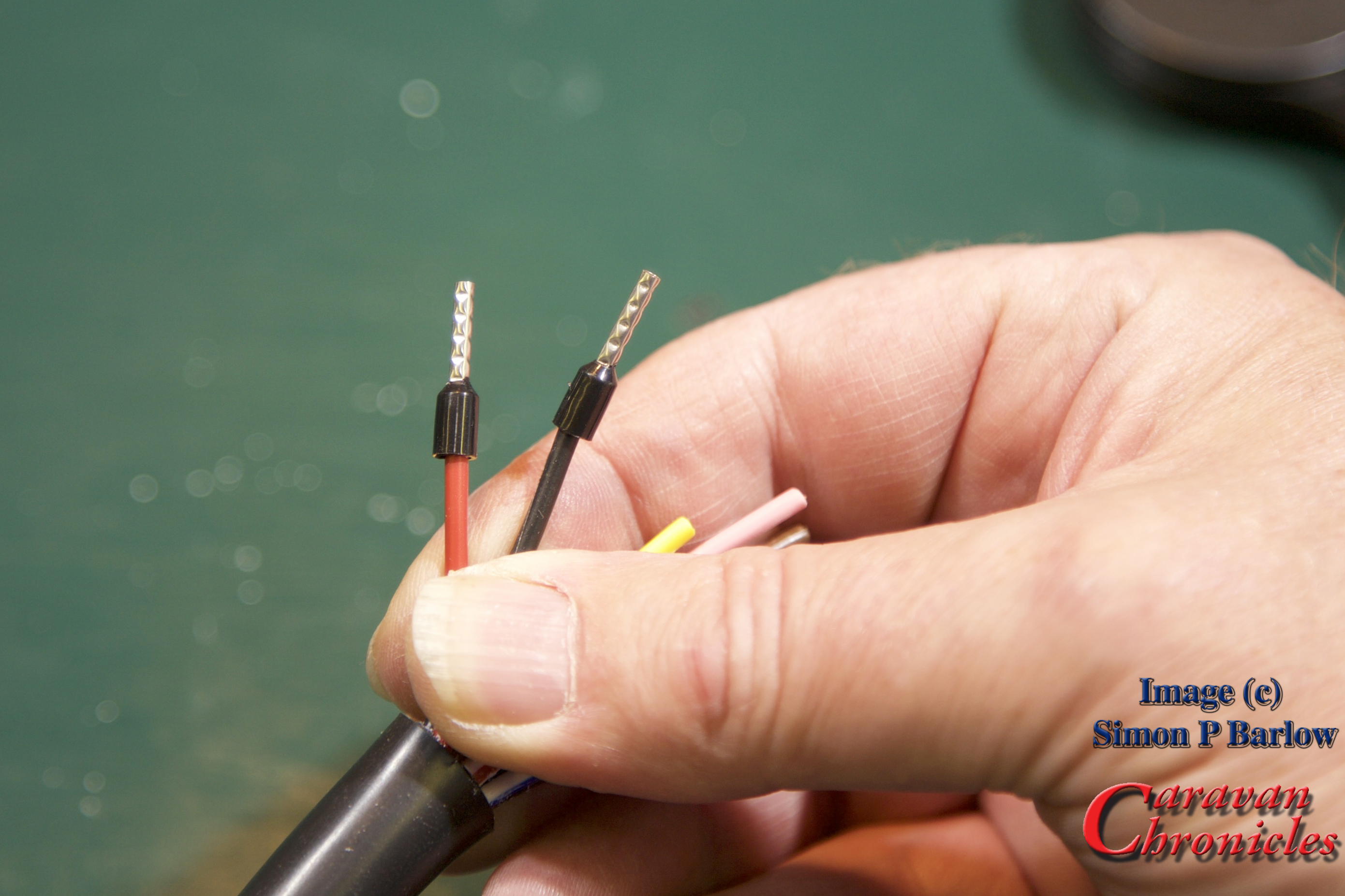
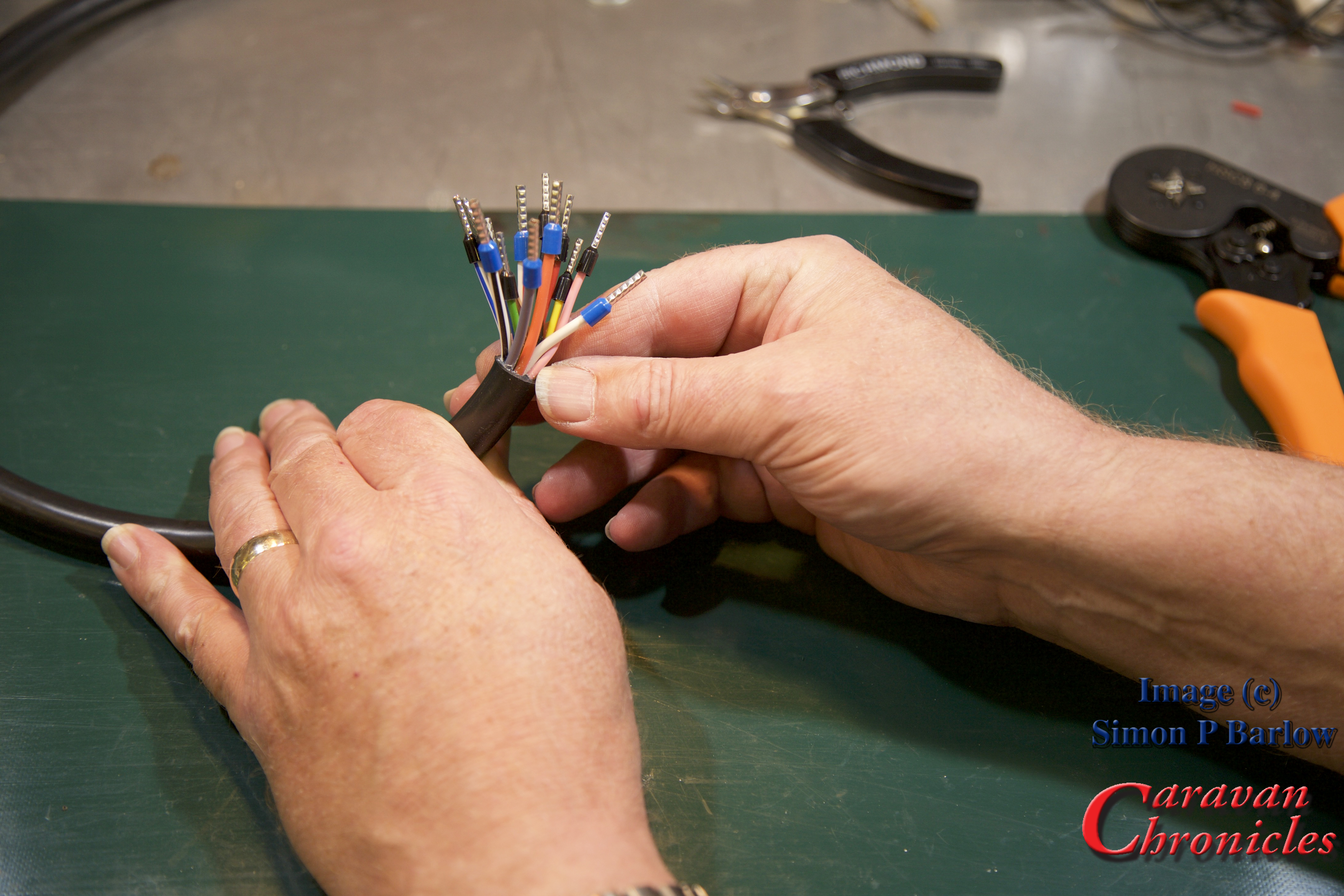
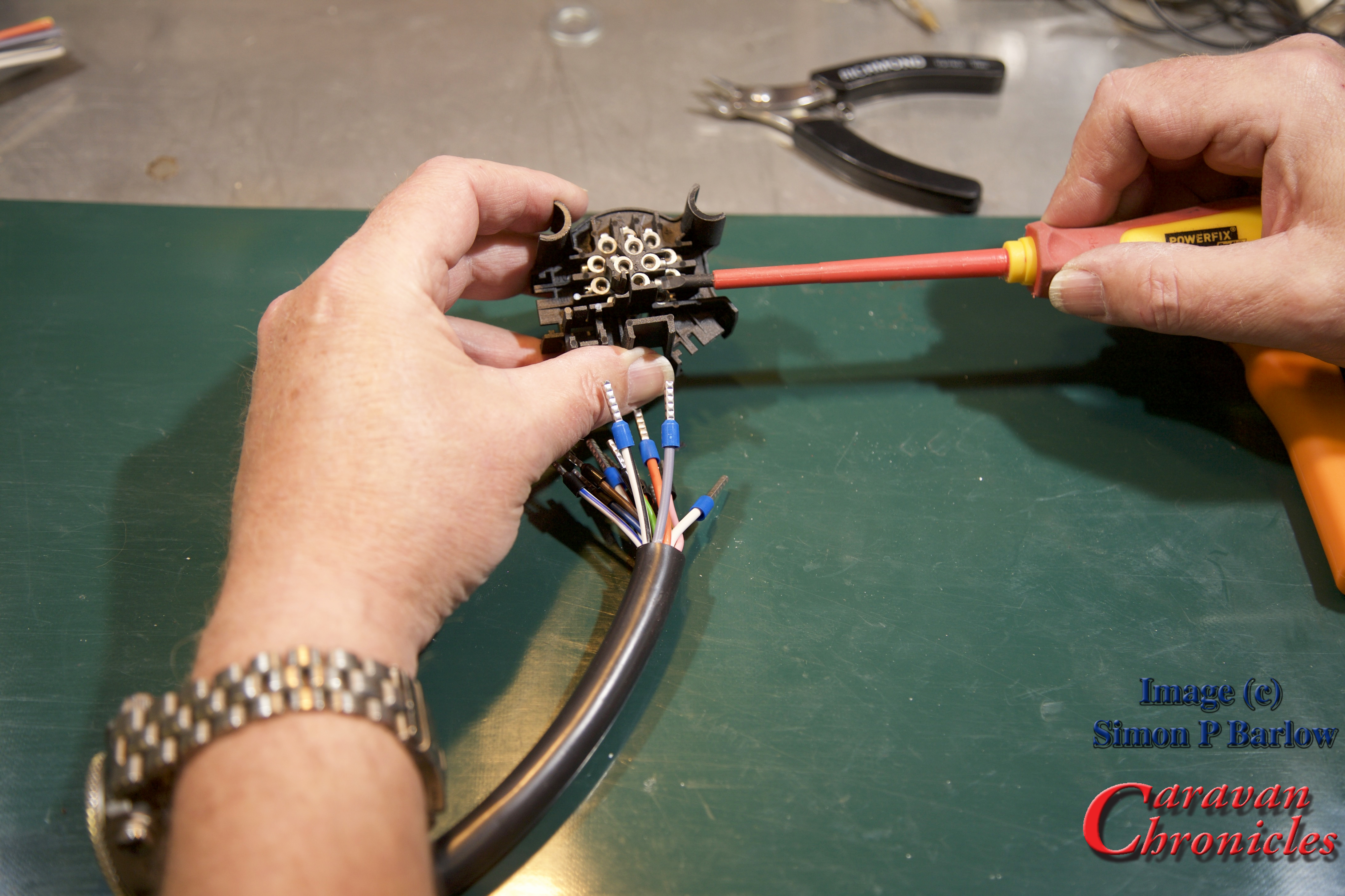
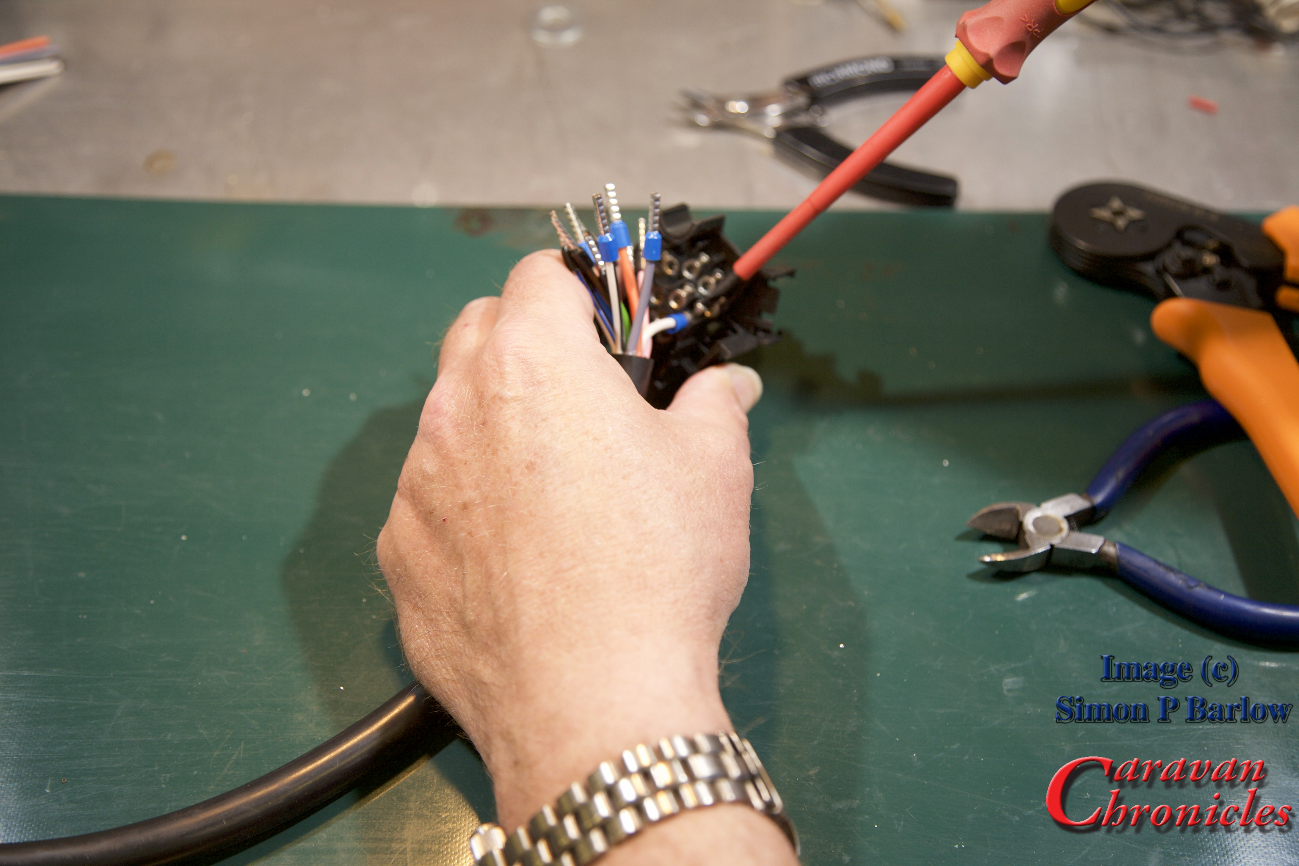
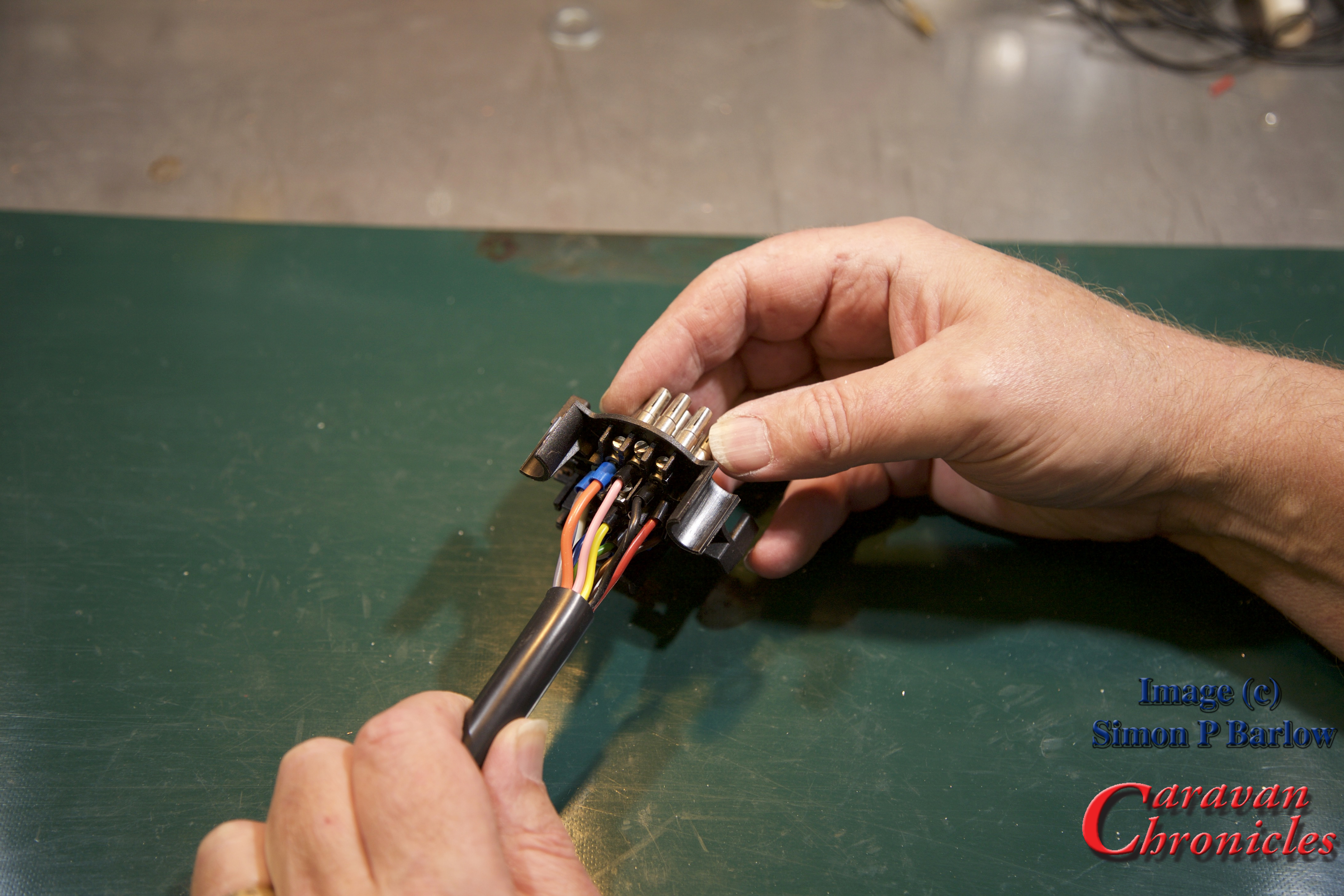
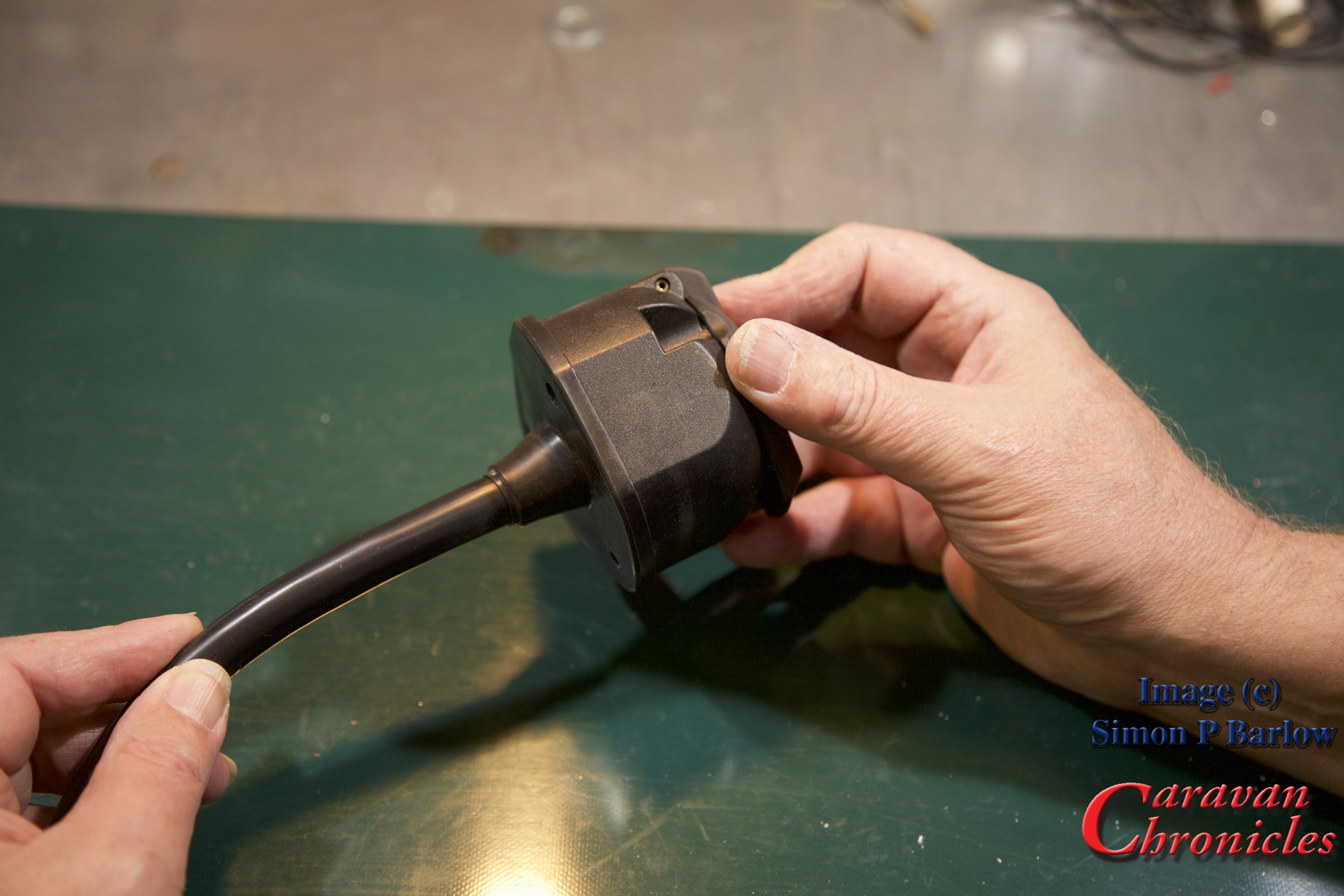
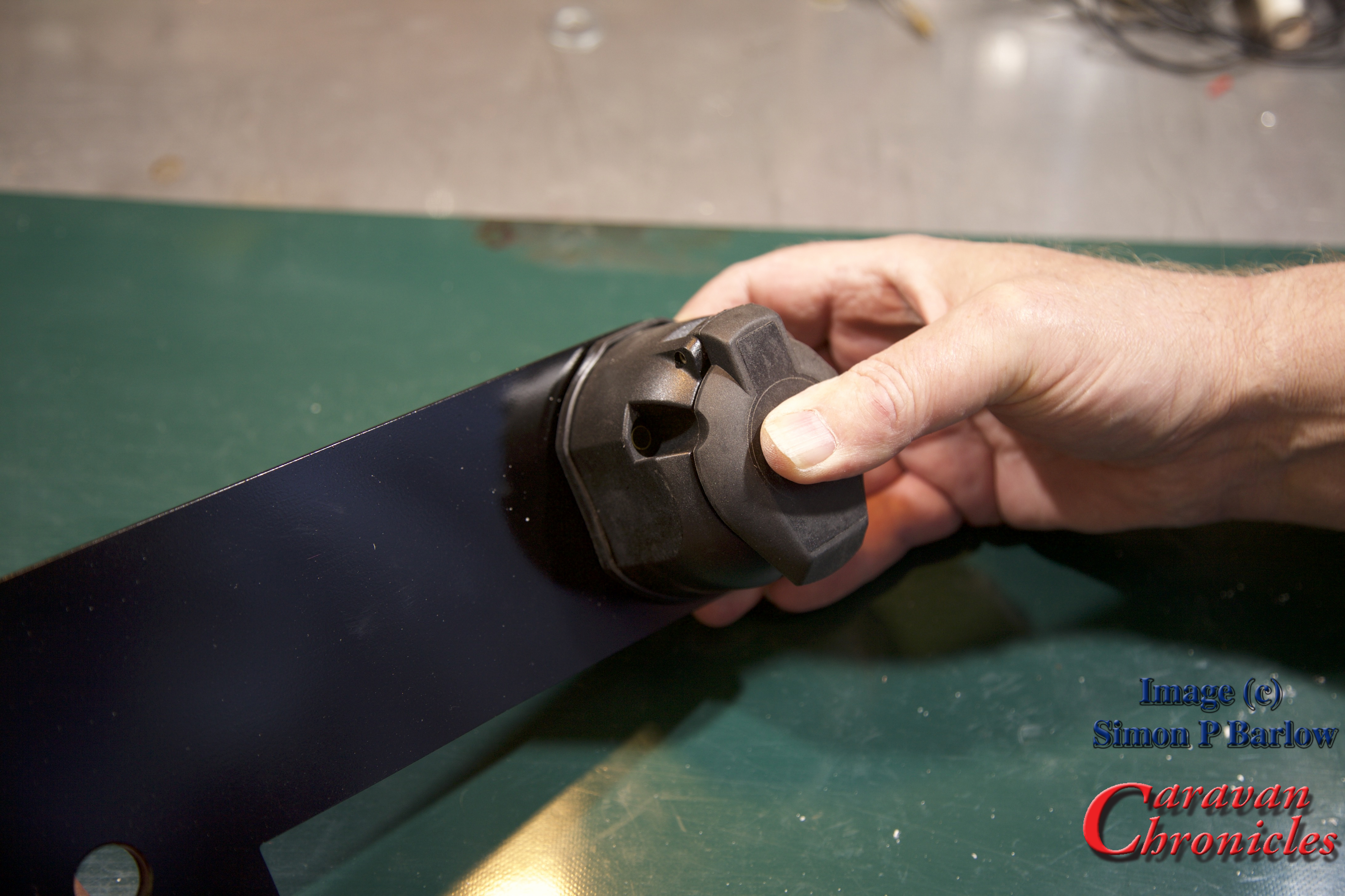
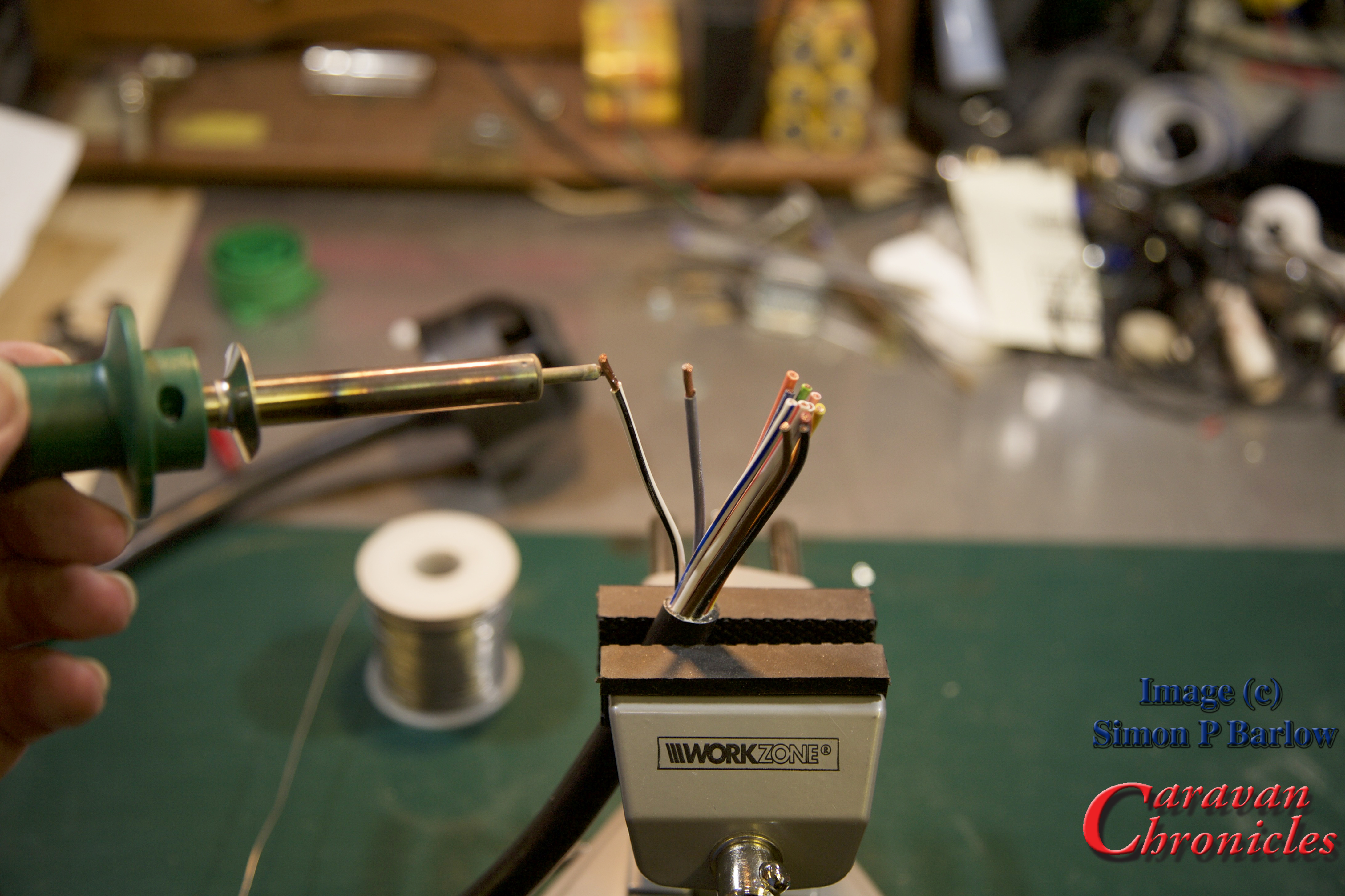
Every cable should be terminated. Period. There shouldn’t be any cables in an installation that don’t have a crimped (or soldered) termination. Even if it’s a screw terminal such as those found in joining blocks or 13 pin plugs.
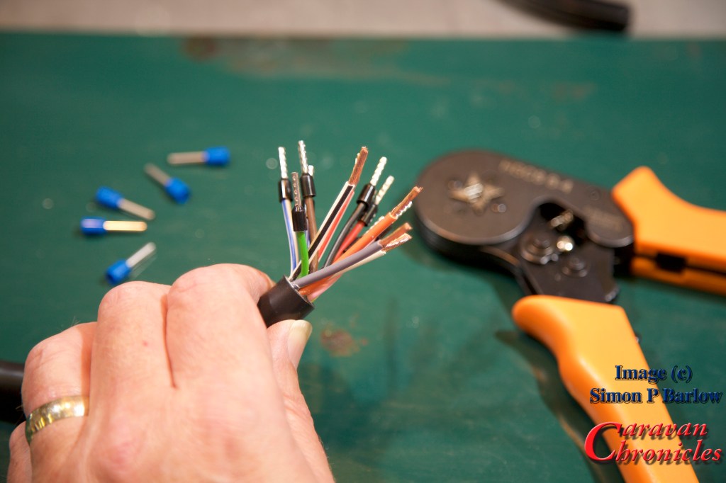
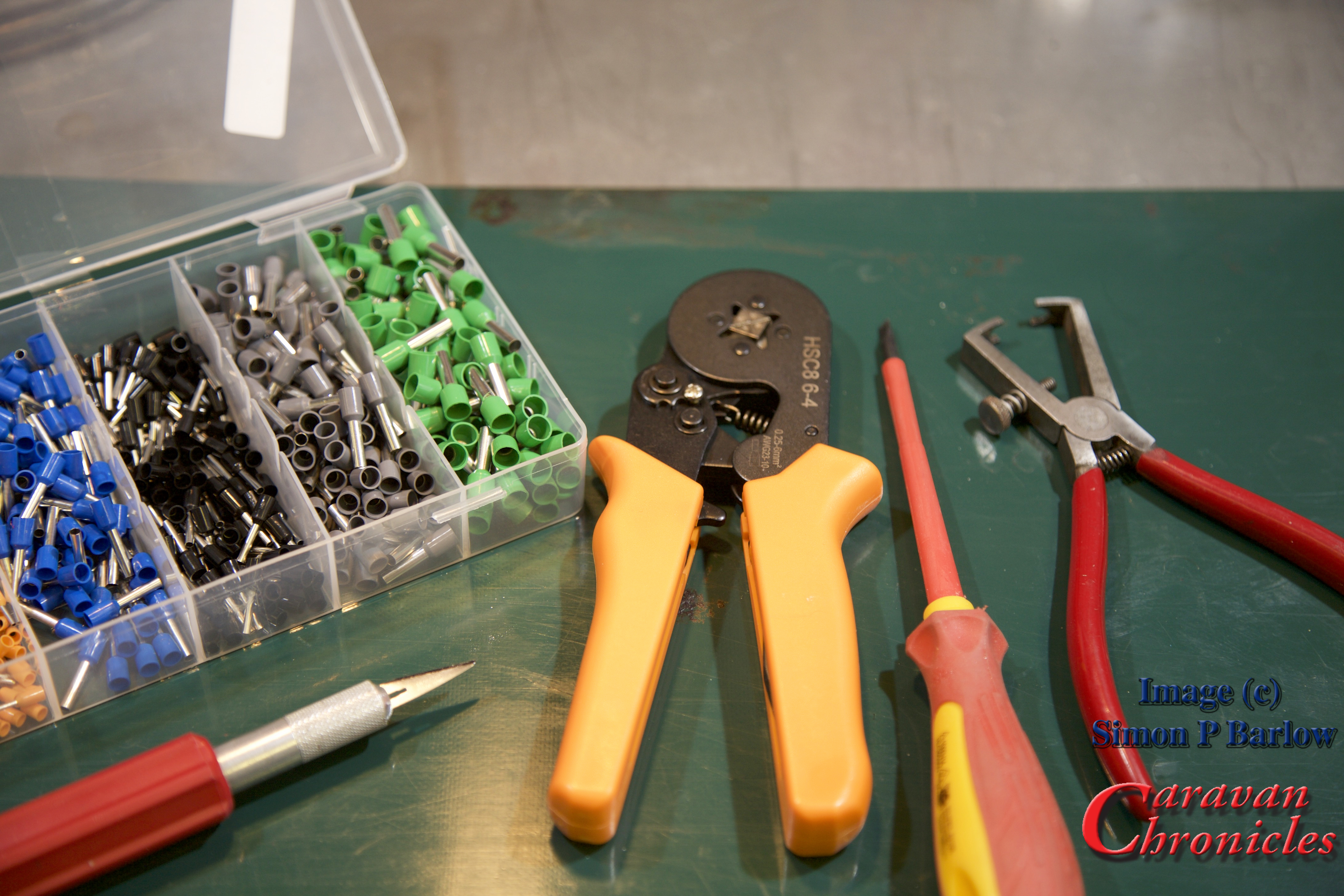
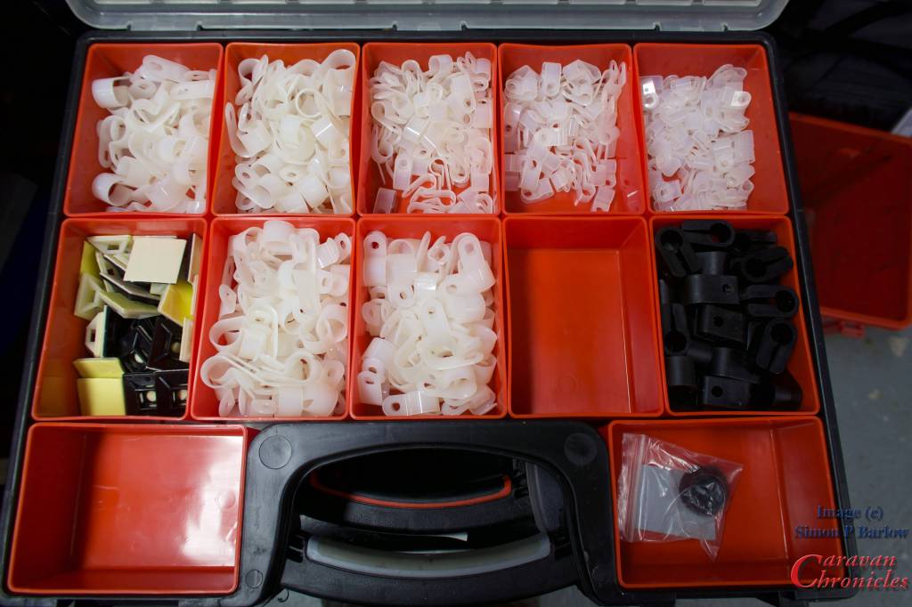
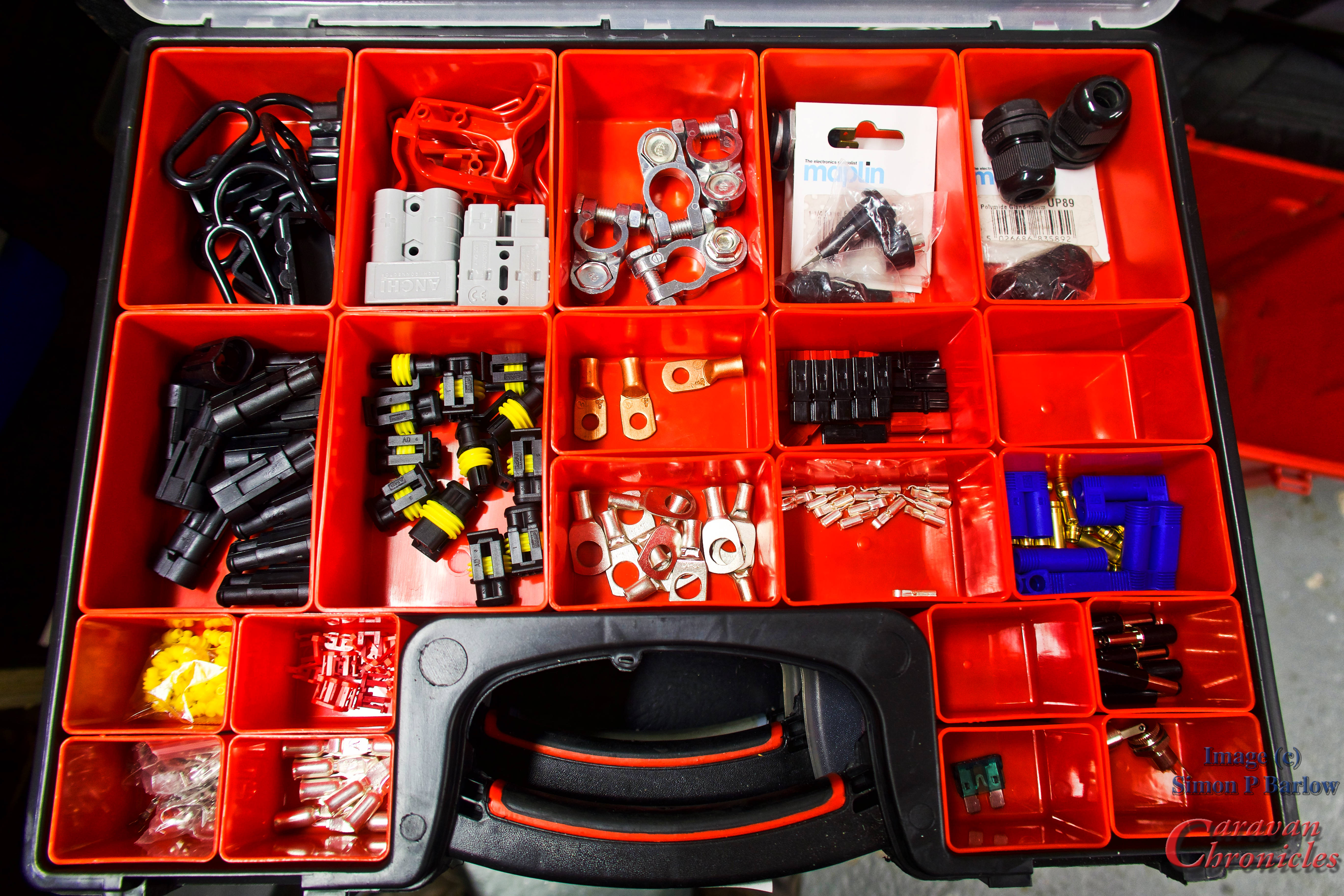
If you are embarking on a wiring project, its always best to start building up your stock of terminals. I usually buy selection boxes of terminals on line and supplement these with bags of single type connectors for the more commonly used ones. To keep everything organised tote organiser boxes are my preferred option.


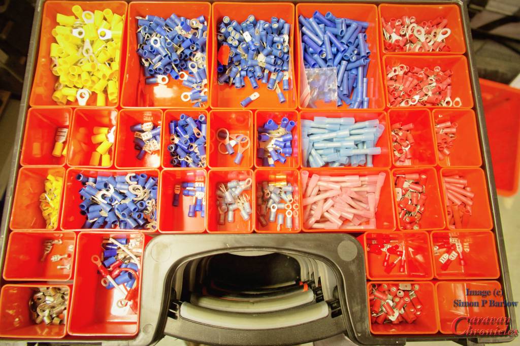

There is nothing more annoying than running out of the something and its always just as you want to finish a project off so you end up cutting corners.
For some of the larger cables, if you don’t feel up to making your own terminations there is usually a local auto electrician available that will terminate them for you for a small charge. However, a crimping tool that will terminate up to 50mm cable is not that expensive – around £27 and will probably work out cheaper in the long run. I’ve a link to the one I bought via Amazon and regularly use in the SHOP page.
Get the size right…
Selecting the right size or gauge of cable is critical. There are two factors that determine what gauge of cable to use for a installing any particular circuit. The maximum current that’s going to be drawn and the length of the cable. Once you have selected the right size cable then means you can select the right size fuse for the circuit. Never fuse a circuit greater than the current capacity of the cable.

You can download these and other drawings from the Electrical Drawings page in the drop down menu under “Document Library”
I generally tend to list what is going to be installed, then work out all the gauge for the cables for the circuits. From there it’s easy to see which is going to be the most popular gauge and rather than buy several different gauges of cable try to select a limited selection of gauges.
Always go for the safe option of over specifying the gauge of cable for any particular circuit. If it’s a 10 amp circuit and you have used cable suitable for a 16 amp circuit, it doesn’t mean however you need to use a fuse greater than the 10 Amp circuit requires.
Something else to consider too. Most 12 volt cables are copper, however if you are installing them in a less than ideal environment, such as a boat, you may want to opt for tinned copper cables. These are far less susceptible to cable corrosion. Even in the best marine installations I’ve seen copper cables corrode through in less than a couple of years.
Cardinal Sin! – Never ever use two smaller cables to make up the equivalent of one larger capacity cable. You would be surprised how many times I’ve seen this… sometimes done by “professional” tow-bar installers when reported poor leisure battery charing or poor fridge performance is reported and the voltage drop is too great.
Wiring Looms – wrapping it up properly!

Dressing cables into looms is not difficult nowadays. There are many options available on the market to help you produce a professional looking finished product. I personally like for looms within the vehicle using a felt finished looming tape. You don’t wrap it so it overlaps but at a sharp enough angle so as it spirals round the cable bunch it leaves some of the cables exposed.
Felt is good as not only does it keep the loom together, it allows quite a bit of flexibility and prevents cables from rubbing or banging on flat surfaces making a noise.
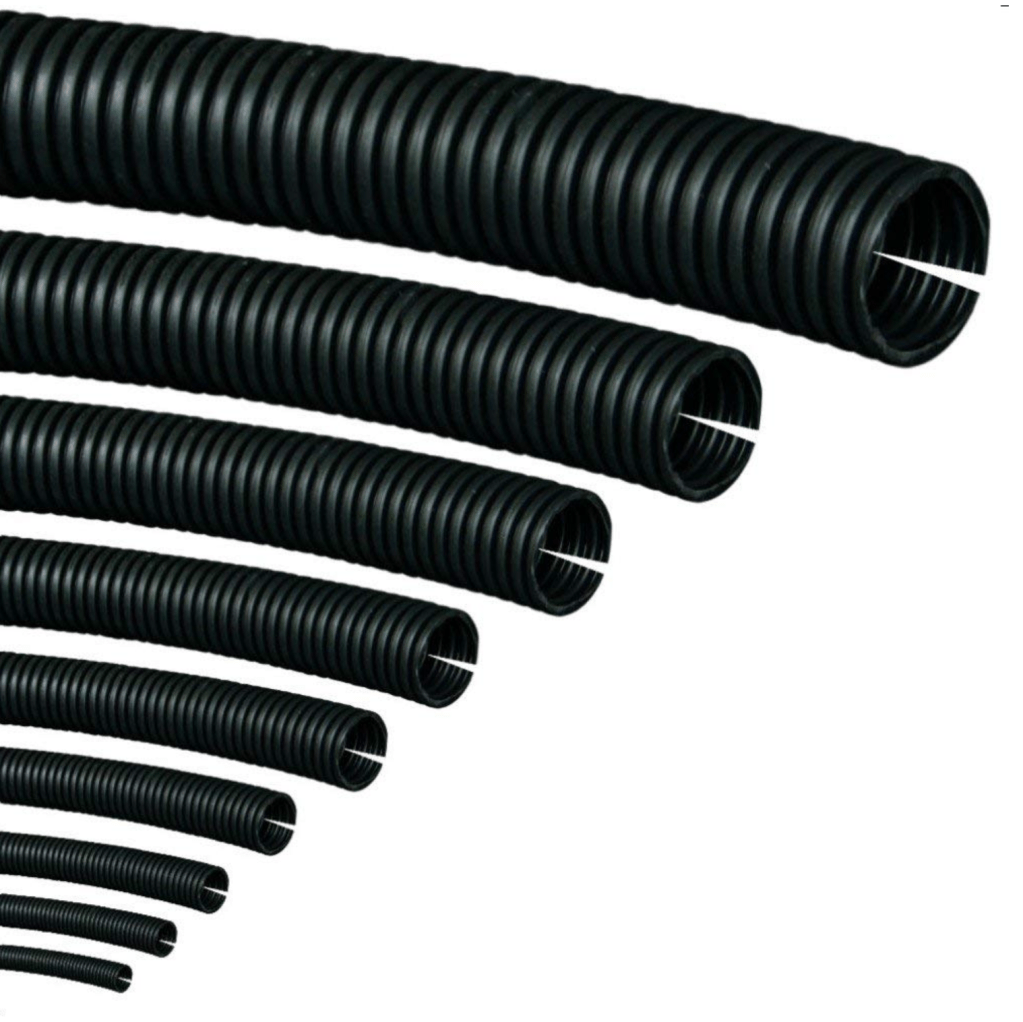
For any cables outside the vehicle body there are two options depending on use. In the main I’d go for split tube conduit. It’s available in various sizes and can be bought in either cut lengths or rolls. The other option is to use self amalgamating tape. It looks like ordinary PVC tape but as you wrap it round you stretch it and it releases a chemical which when overlapped onto its self becomes a permanent bond, effectively making a sealed tube. It is generally however fairly inflexible. Both have their place.
Anything in the engine bay or underneath the vehicle I use split tube and generally only resort to self amalgamating tape to seal inline joints.
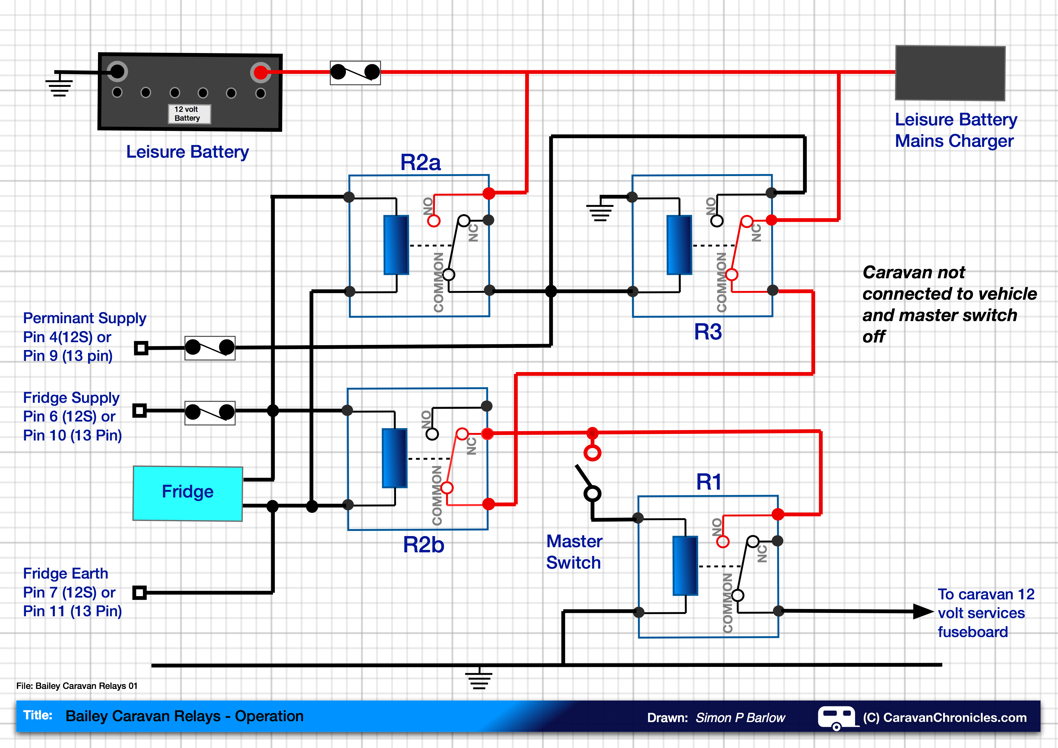
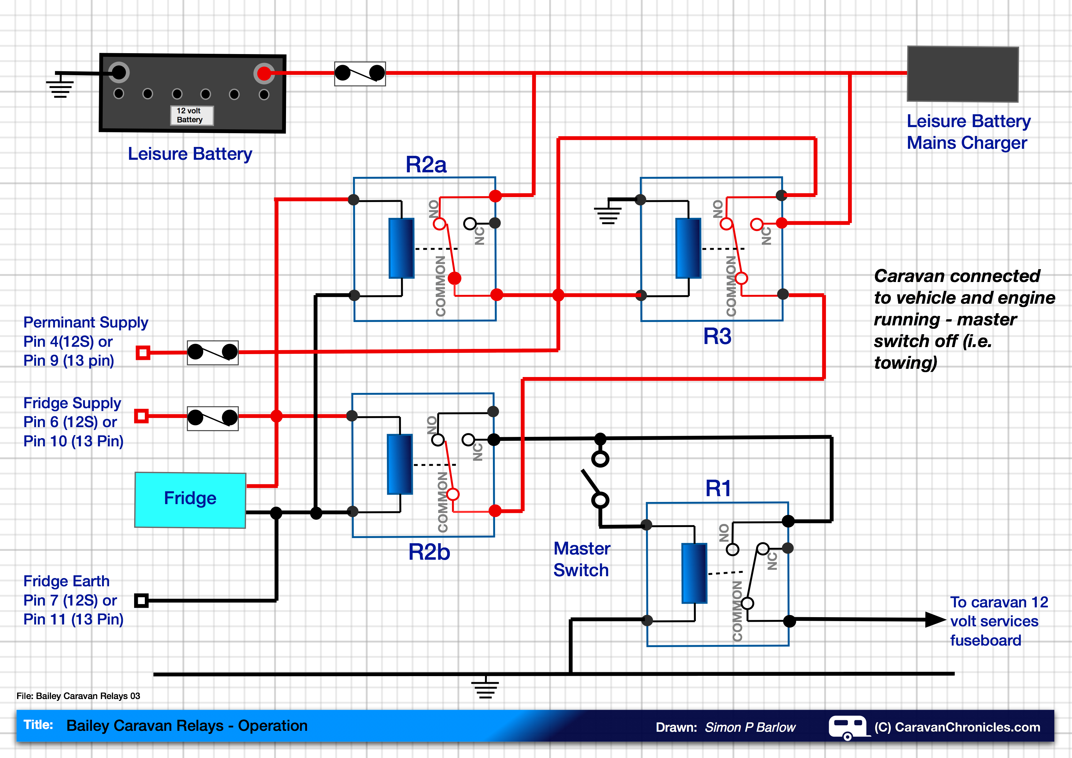
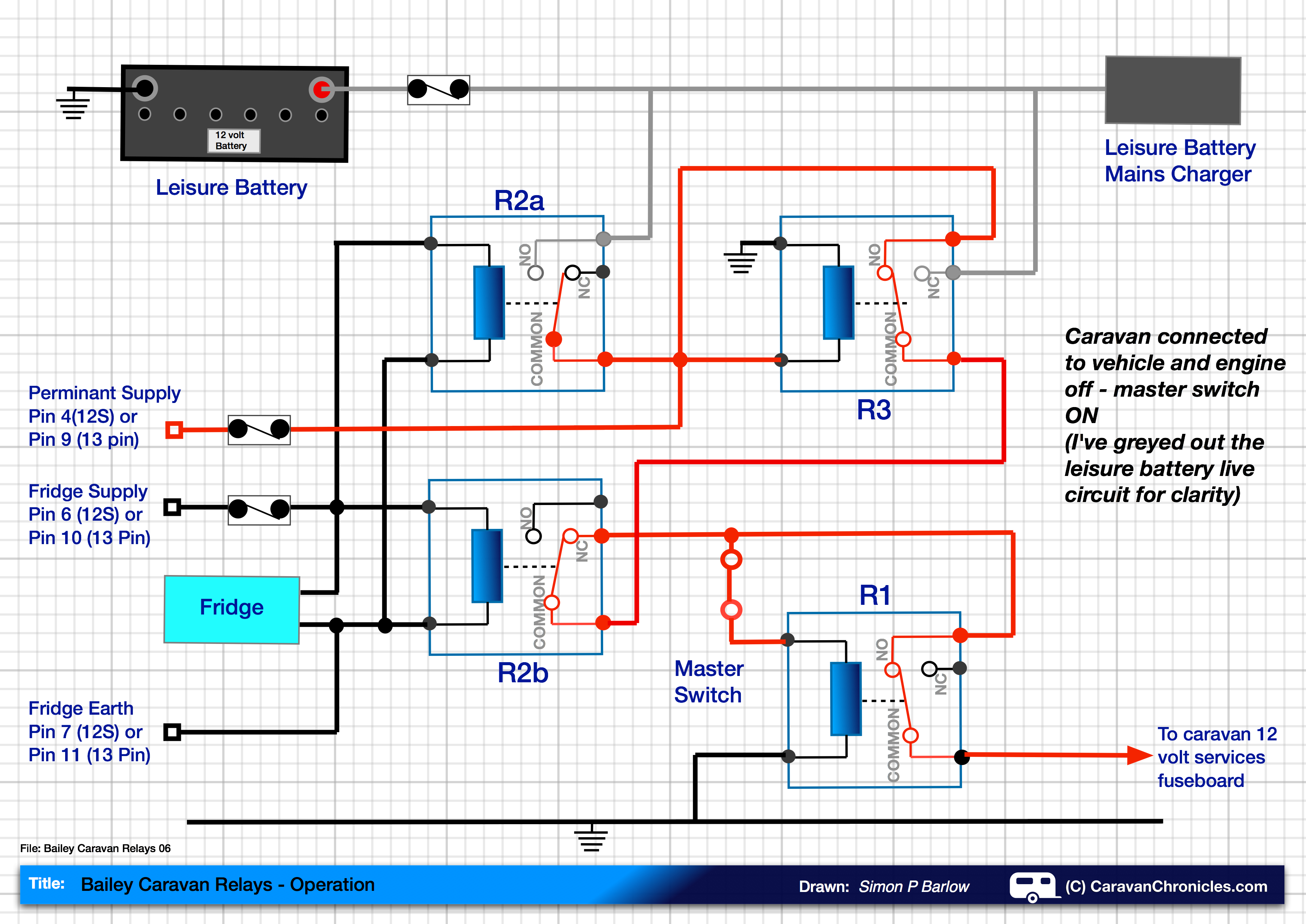
Relays….. yes or no?
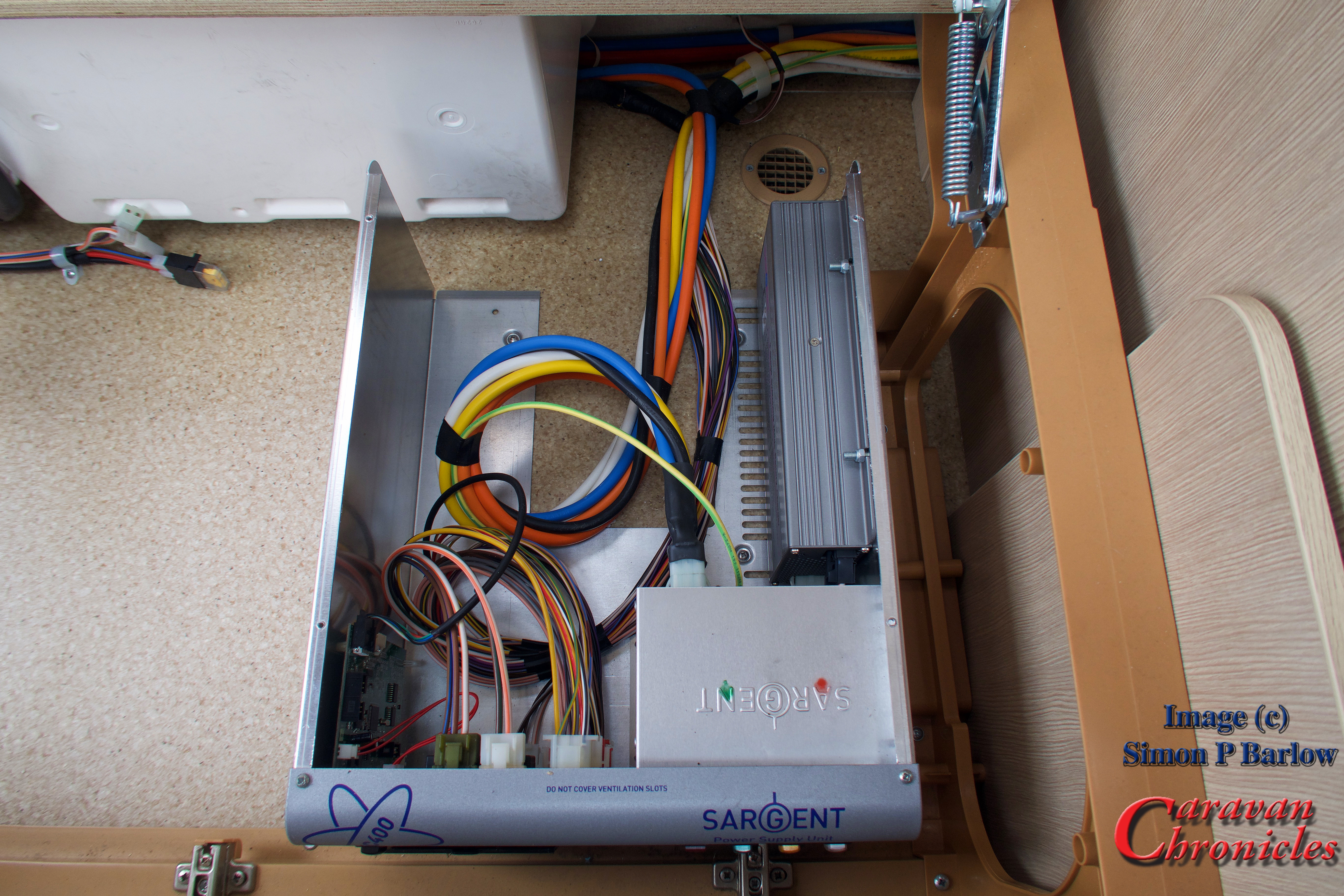
For me its Yes. I much prefer locating all the relays in one place therefore minimising the amount of heavy cable. By using relays to do the heavy switching you can use smaller and sometimes more attractive switches. I have in the past used 7 core trailer cable to connect 4 switches including LED indicators back to a relay bank rather than make up a custom wrapped loom.
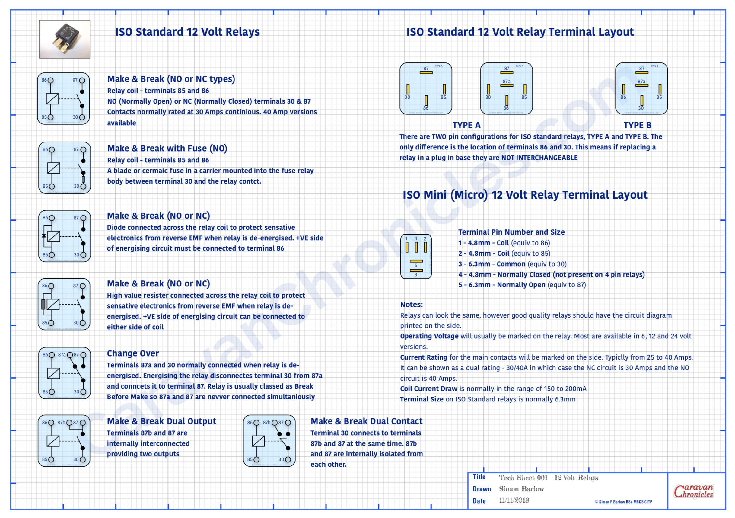
You can download these and other drawings from the Electrical Drawings page in the drop down menu under “Document Library”
It also makes tracing faults easier, as it’s simple to test if a switch is working, you can hear or sometimes feel the relay operating as you operate the switch. Its unusual to have a fault with a relay but quite simple to test… just unplug and swop over with a known working relay. If all the relays are located together it makes this task and testing the feed to the relays so much simpler. From that point all you need to check are the two wires going out to the device and the device itself.
Obviously some circuits don’t require a relay or if it’s designed to be turned on for a long period… such as a diesel heater, then adding a relay will just increase current draw, albeit small, on the leisure battery. A bit of common sense can easily determine if you should opt for a relay or not.
Grommet?…(no not Wallace’s friend!)
Whenever a cable or cables pass through anything solid you should use a grommet. You would be surprised at the amount of damage I’ve seen to cables due to either not installing a grommet to an insufficiently sized (too small usually) grommet.
When ever I pass either a cable or loom through a bulkhead for example I like to supplement a grommet with a bit of heat shrink sleeving over the cable as well. Even passing a cable through an existing grommet from the engine compartment to the interior, adding a length of heat shrink sleeve won’t do any harm.

Having a handy selection of grommets available before you start threading wires through is far better than trying to install protection afterwards. You’d also be surprised at how many cables I come across that have been damaged while pulling through holes in metal and wood panels. Always better to start with a grommet or two! Where a cable or loom passes through a grommet, it’s aways best practice to try and anchor the cable or loom either side of the grommet to something solid using “P” clips. This will reduce the chances of ‘fretting’ with the movement of the vehicle.
While we are on grommets…. a quick note about cable-ties (zip-ties). Stop doing them up so tight! I’ve come across cables cable-tied to a chassis rail so tight that the cable-tie has cut into the insulation and is fretting the conductor inside. Cable-ties are generally made out of a harder plastic than the cable insulation so will over time wear away at the insulation.

Get yourself a cable-tie tool that not only allows you to precisely control how much tension you put on the tie but also cut the end off so that there isn’t a wrist slashing booby trap lying in wait for some unsuspecting person. I use a fairly cheap pair (left). I think they were around £8. So not really expensive. But they make a nice neat job of installing multiple cable ties with the correct tension and the ends cut cleanly off level with the lock tab. You can buy ones that have a tension dial built in so you can set them to a pre-tension, but I find after a bit you know just how much to squeeze the handles to get the correct tension.
So what is the correct tension… well if you are doing them up so tight an elephant could dangle on the cables then that is too tight. They should be tight enough so as not to slip but you should be able to spin them round the cable(s).
Cable-ties really should not be used to make looms or anchor cables or looms to anything solid. If you want to make a loom, wrap it in specialist loom tape. If you want to anchor cable or a loom to something solid use a “P” clip. If required… use a length of heat shrink to make the loom a tighter fit in the ‘P’ clip.
I know you are dying to ask…. when do I use cable-ties? Well generally at the installation stage to get things to stay in place before installing P clips or if I have to run a new loom along the same path as an existing loom, I generally opt for cable-ties to hold them both together (as long as the original is suitably anchored to support both)
While we are talking abut cable-ties… I have seen the worst kind of mistakes in the use of them. It is not OK to cable-tie anything to brake lines, fuel lines, vacuum lines, hydraulic hoses, coolant hoses or steering components (yep one bright spark cable-tied his front LED light bar wires to some of the steering components!)
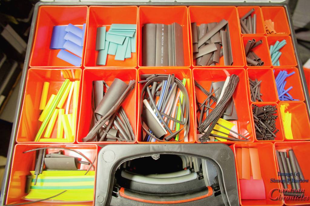
Heat Shrink Tubing
An absolute must have in my opinion. There are two main types – plain and pre glued. The plain are the main one you would use, while the pre glued are great if you have to over sleeve a connection to make it waterproof. As you heat up the pre-glued type, the glue softens as the tube strings and bonds to the cable as everything cools. They can be a little more rigid when installed, so make a service loop in the cable. The finished covering is usually waterproof enough for brief submersion if done correctly.
Having a selection of sizes and colours is handy and assortment boxes of multiple sizes and colours can be bought on line cheaply enough. In the workshop I use an old paint stripper heat gun on low power as I find that is more controllable than a flame.
Bridging the gap… something in the future?
Although not so common in the UK, in Australia and the USA wild camping (boon docking) is probably as popular as campsites. To this end trailers and caravans usually have much larger battery capacities than anything found in Europe. It’s not uncommon to find outfits with 600 to 800Ah battery banks recharged mainly be solar, buy increasingly (especially in Australia) an additional bridge between tow vehicle and trailer is made using heavy duty “Anderson” connectors and cables capable of supplying upwards of 60 Amps from the vehicle to the leisure battery bank.
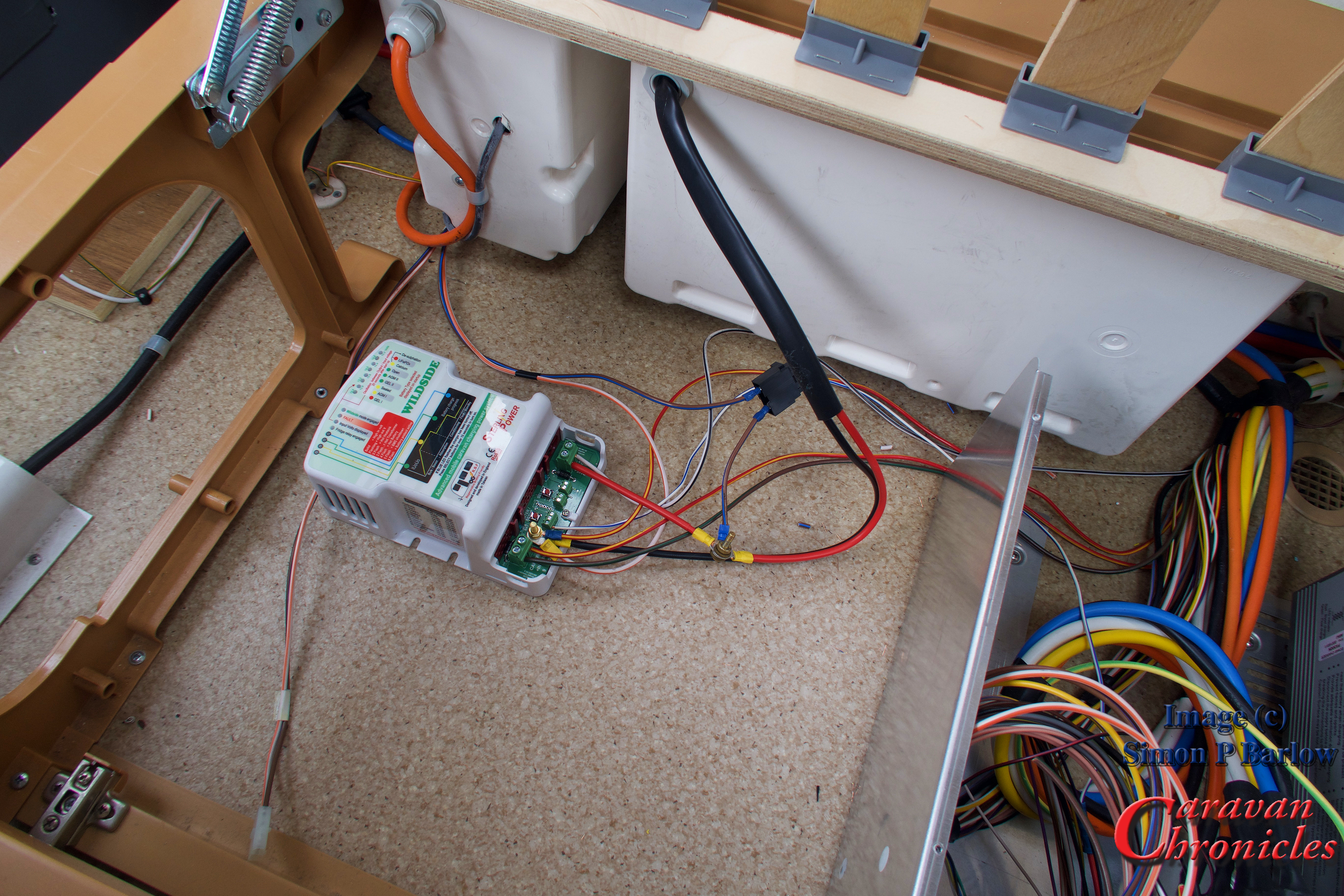
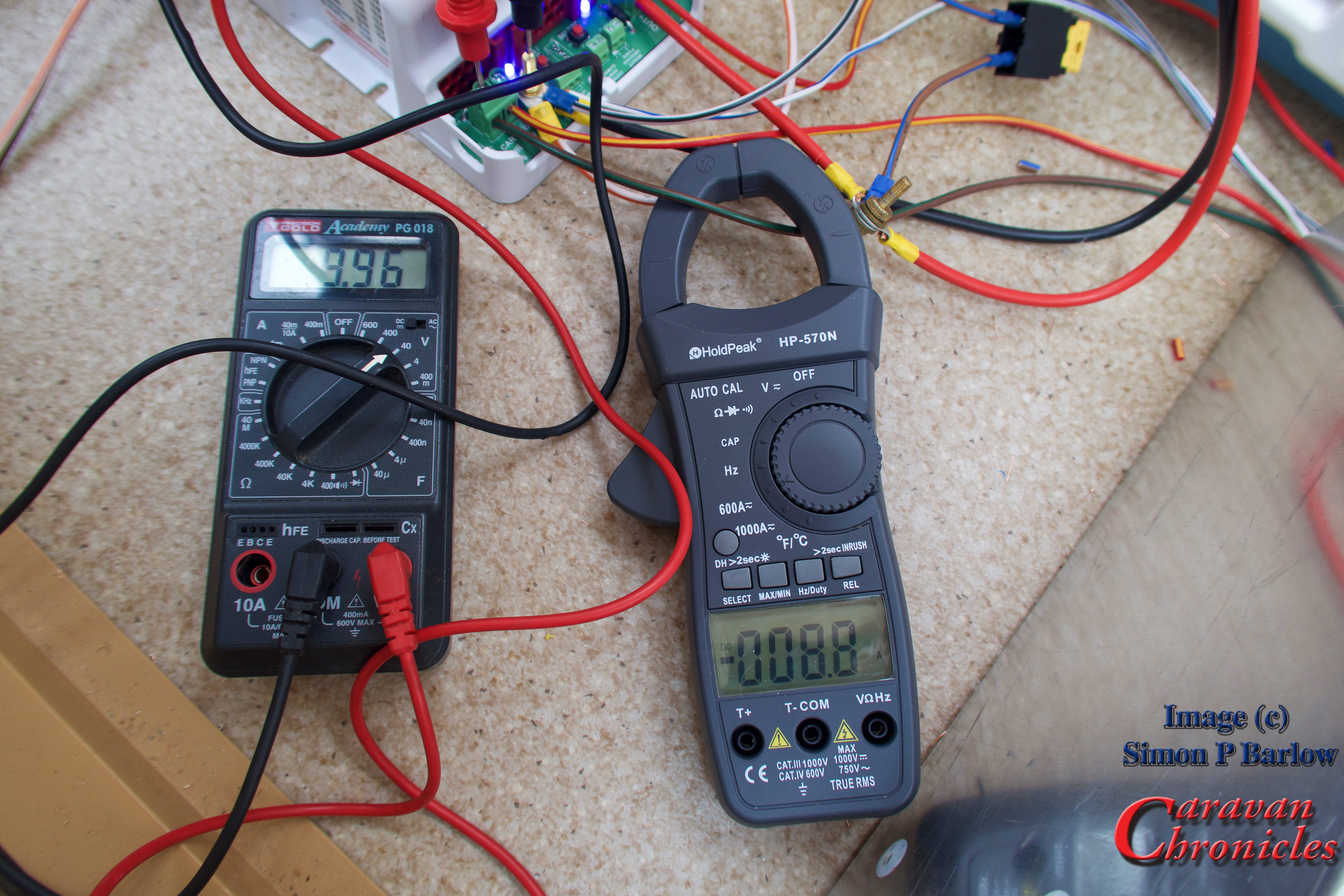
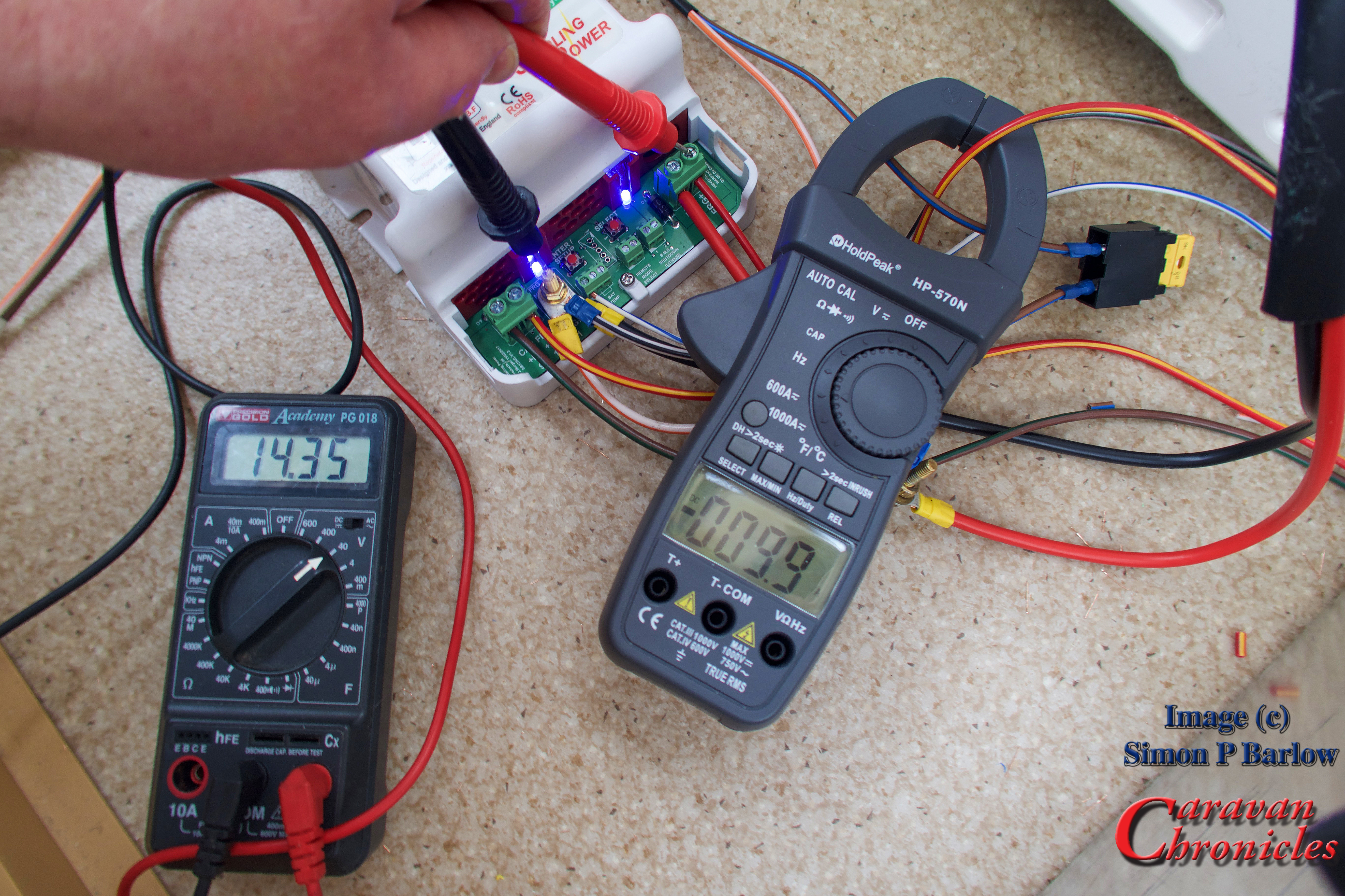
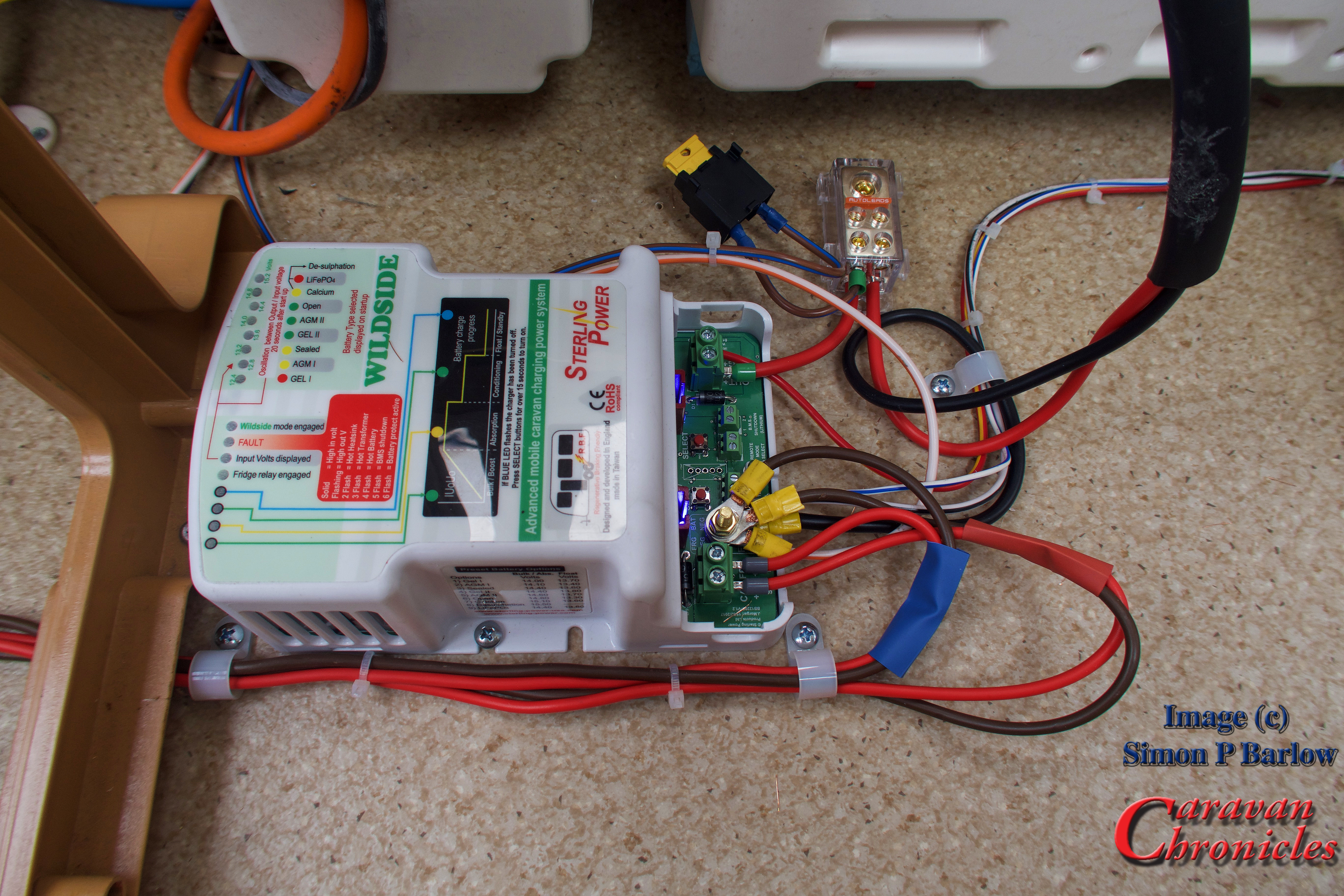
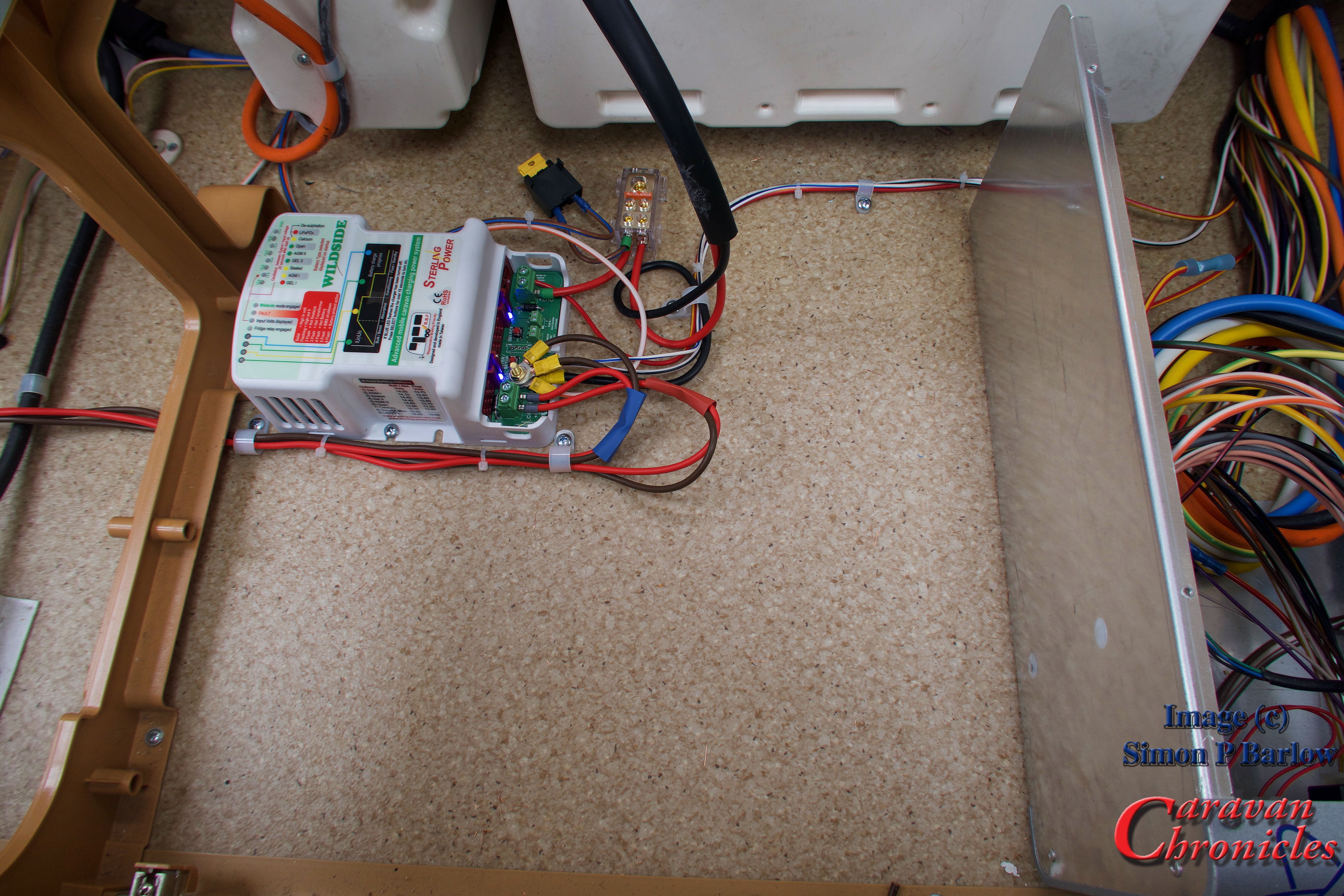
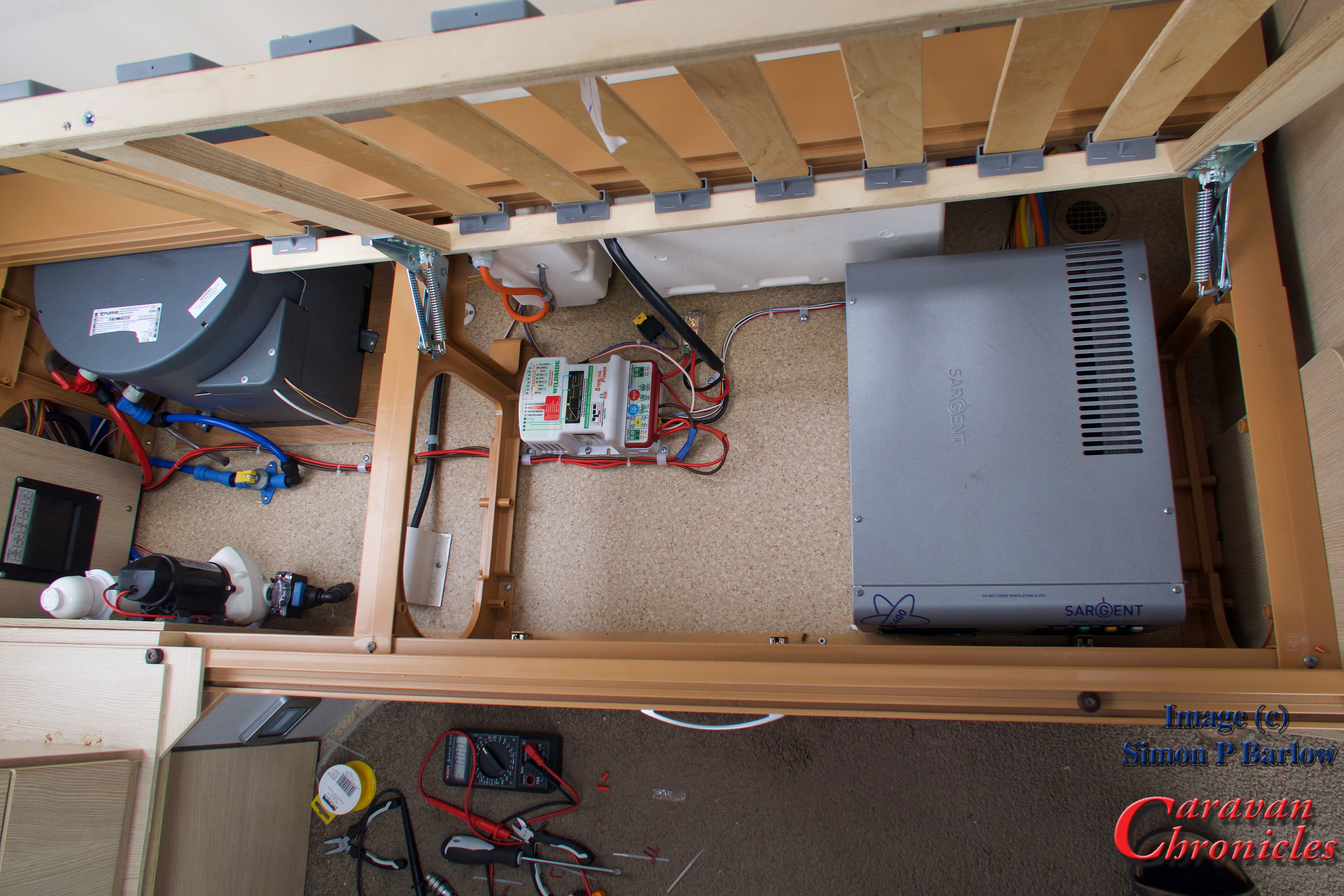
With the cost of lithium batteries reducing almost daily, I can foresee very soon that light weight lithium batteries will be installed in caravans. The down side of this currently and trying to retrofit Lithium is the existing charging setup of current European vans is not really suitable for looking after these type of batteries. We have a Sterling Power Wildside unit installed in our caravan which allows us to charge any type of battery chemistry, including lithium when connected to the tow vehicle. The draw back is the caravan’s inbuilt charger is only capable of wet lead acid or AGM. I think that a high capacity DC to DC charger installed in the vehicle and an additional cable to supply the caravans battery banks may not be too far away. It’s something you might want to keep in mind for the future. It’s something I’m looking into currently.
Well, that’s a bit longer than I anticipated and there is still a few things to cover. If you made it this far…. take a toffee out of the jar… well done! If you think I missed something or would like me to cover something specific, drop me a comment below.
- Related posts you may like…
- The Problem With Information From The Internet…
- A Request…
- Euro 6 Engines, Smart Alternators and Your Leisure Battery…
- For Anyone Restoring A Vintage Caravan…
- Overland Vehicle Electrics and Other Stuff…
- A Quick Fault Finding Tip…
- Something For Your Toolbox…
- Getting All Charged Up – Update 2…
- Is A Euro 6 Engine Killing Your Leisure Battery?…
- Getting All Charged Up – Update
- Getting All Charged Up – Part 3 “The Install”…
- Getting All Charged Up – Part 2…
- Getting All Charged Up – Part 1…
- Smart Alternators: how they affect Caravans and Motorhomes….