• Home
  • Help Guides
    • Storage Sites
    • Equipment Reviews
  • Document Library
    • Electrical Drawings
  • Photo Gallery
    • Caravan Log
    • MPG
  • Trip Map
  • Shop
  • About Caravan Chronicles…
  • Contact
  • Links

Caravan Chronicles

~ not just another caravan blog

Caravan Chronicles

Category Archives: Technical

The problem with information from the internet…

08 Sunday Dec 2019

Posted by Simon Barlow in Caravan Electrical Fault Finding, Caravan Electrics, Electrical, Modifications, Motor Home, Technical

≈ 10 Comments

Tags

Campervan electrics, Caravan Electrics, Electrical Faults, Motorhome electrics, Overland Vehicle Electrics

The problem with information on the internet is that although there is some great advice to be found there is also some less than great…. poor… really really poor advice and sorting out the good from the bad is sometimes not easy.

We are currently pitched on the Caravan & Motorhome club site Beechwood Grange near York and I decided to sit down and pen this post as for the last few months I seem to have been sorting out a number of problems via emails and phone conversations that really should not have arisen.

I’m going to give you a couple of examples of what’s been dropping in my inbox. To protect the inoccent I’m not going to name anyone or the channels. I do have the OK to relate these issues.

Case 1

“Hope you can help, I’m converting a VW Transporter into a camper van and have been following a number of YouTube channels for information on how to do it. It’s nearly complete but I have a problem when I go to use my inverter off grid. The base of the seat starts to warm up and a get a funny smell in the front of the van”

After an exchange of emails and a few photos were sent I eventually worked out what was going on. The 2000W Pure Sine Wave inverter was floor mounted in a cupboard towards the rear of the van where it was convenient for the mains sockets on the inverter to be reached. A suitable size Positive (+ve) lead ran back to the two 100Ah AGM batteries located under the front seat. A suitably sized Negative (-ve) lead also ran back to the batteries and was bolted to the chassis under the seat along with a number of other smaller -ve leads. The batteries were mounted on a wooden platform above this connection. The +ve lead from the inverter went to one battery +ve terminal and a link wire to the second battery +ve tied the two together. The size and rating of this tie wire was a lot less than it should have been.

The -ve posts of each battery had a very short 10mm2 cable going to a threaded stud mounted on the base of the seat and were helpful on to the stud by a star washer and nut. The seat base was a 3rd party metal fabrication hat had been powder coated and bolted to the vehicle floor by 4 bolts and ‘penny’ washers.

What was going on?

When the inverter was operated, it drew current from the battery down the +ve lead. Apart from the fact there wasn’t a fuse between the battery and inverter this side of the circuit was OK. The return path however was a different story. The inverter -ve lead was connected to the vehicle chassis under the seat – not at one of the seat mounting points. The -ve of the two batteries was connected to a stud that was a press fit into the seat base. It didn’t have a hexagonal head just a mushroom head. It was also way under size for the terminals that were fastened to it. The oversize star washer stopped the nut pulling through the terminals. The return current path therefore had to flow into the vehicle chassis, up the four bolts holding the seat to the floor and through the seat base to the push fit stud and finally into the two short leads connecting the battery -ve terminals. The relative high current drawn by the inverter through the single undersized push fit stud and the four floor bolts that were securing a powder coated frame with penny washers presented enough resistance for 60 or 70 Amps of current to start to heat things up a bit and burning off some of the powder coating. 70 Amps passing through a 0.1 ohm resistance will generate 490 watts of heat (calculated using R x I2 = P) this is why it’s critical to get any cabling correctly crimped with the right terminals for the job.

Conclusion

Don’t rely on the vehicle chassis as a return path. install cables for both ‘legs’ of the circuit from source to destination and back again.

There wasn’t a fuse installed near the battery. Any cable coming from a battery MUST have a fuse close to the battery before it goes off anywhere to supply anything else.

If a cable terminal requires an M4 nut and bolt…. use an M4 bolt nothing smaller will do.

If you are ‘grounding’ to anything metal, clean the surface, use a dab of protective dielectric grease (there are different ones for steel and aluminium!) and make sure any washers used work correctly. Flat clean washers for electrical contact and a star washer as a mechanical anti vibration measure to stop the nut loosening.

Case 2

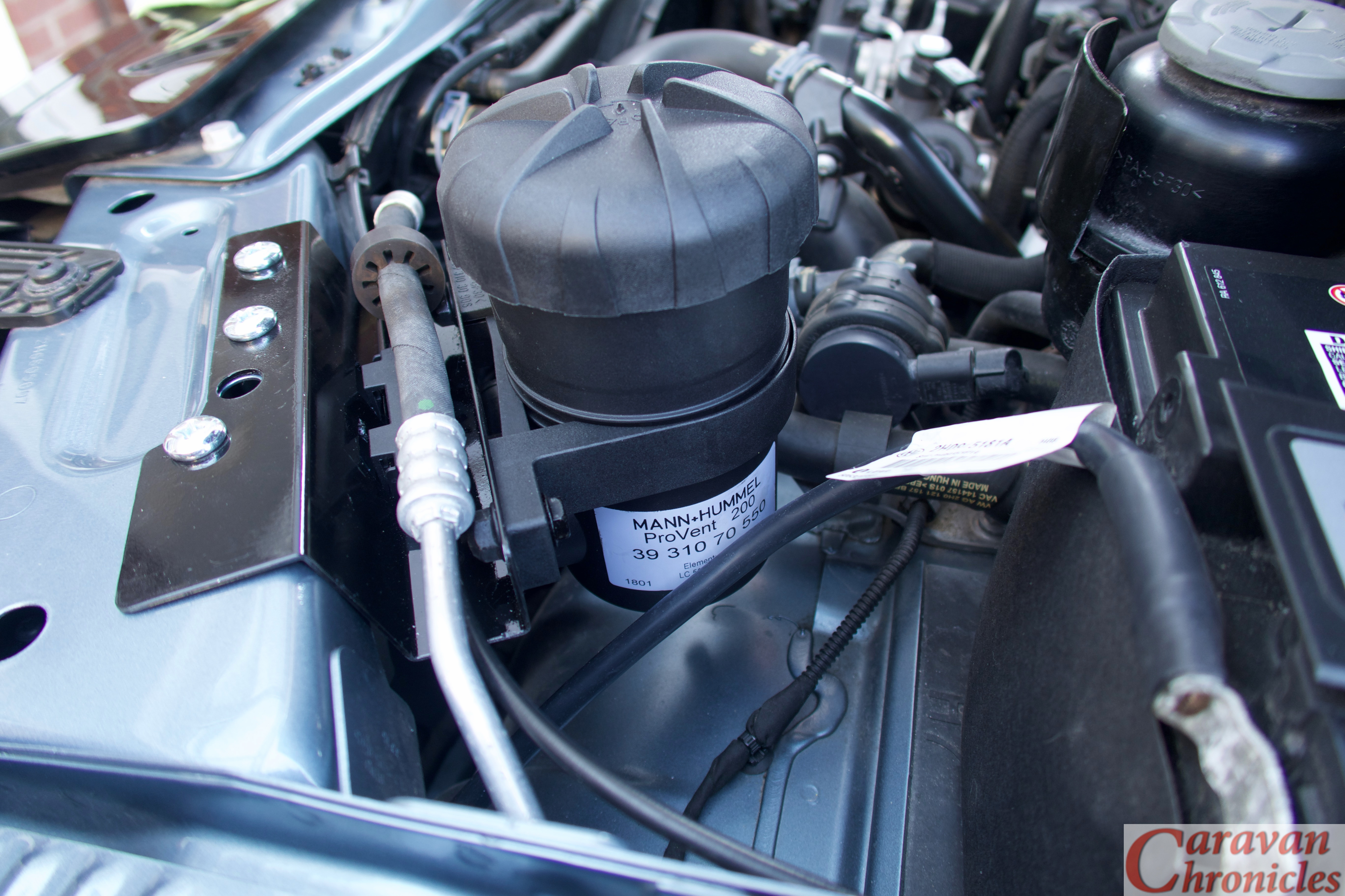
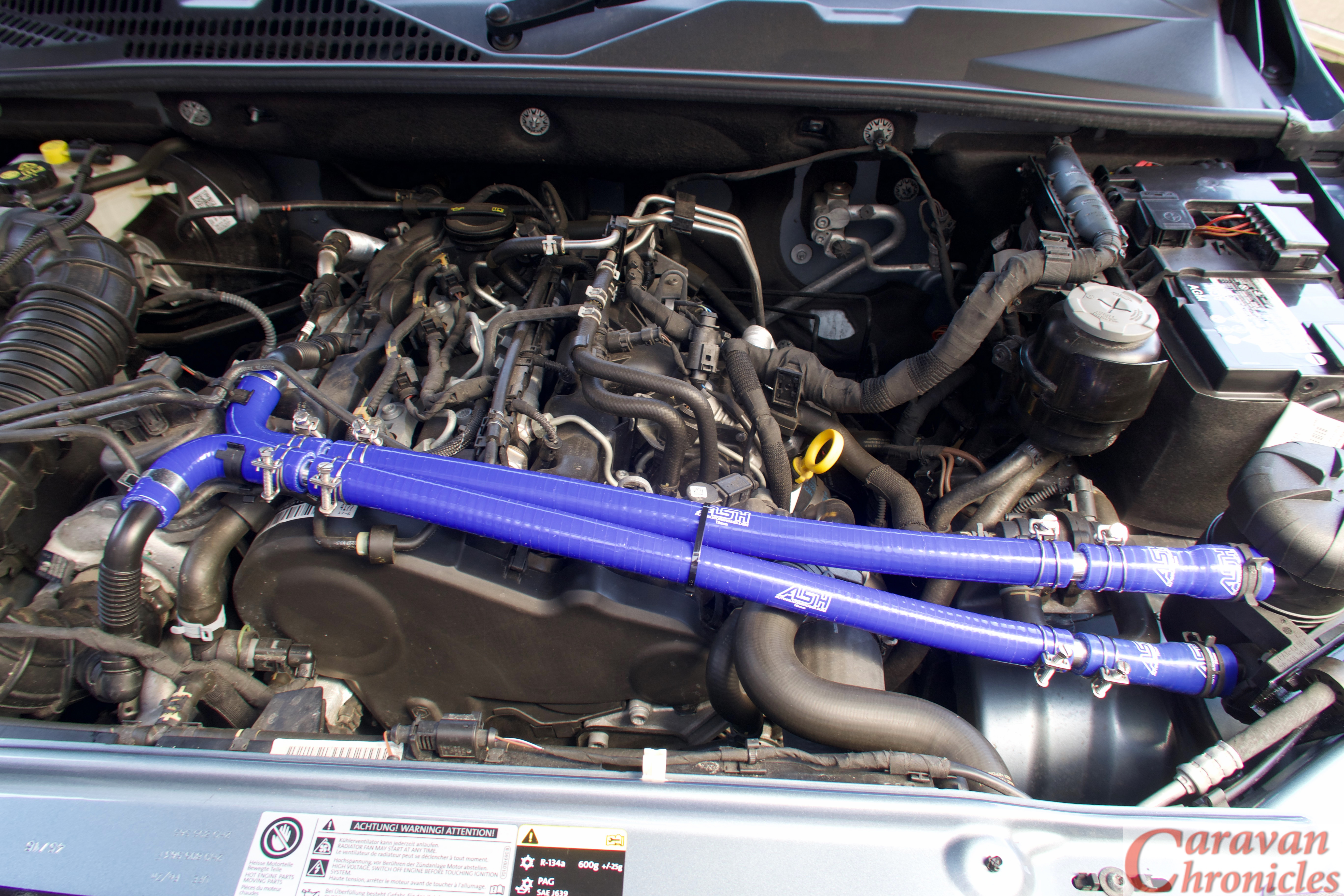
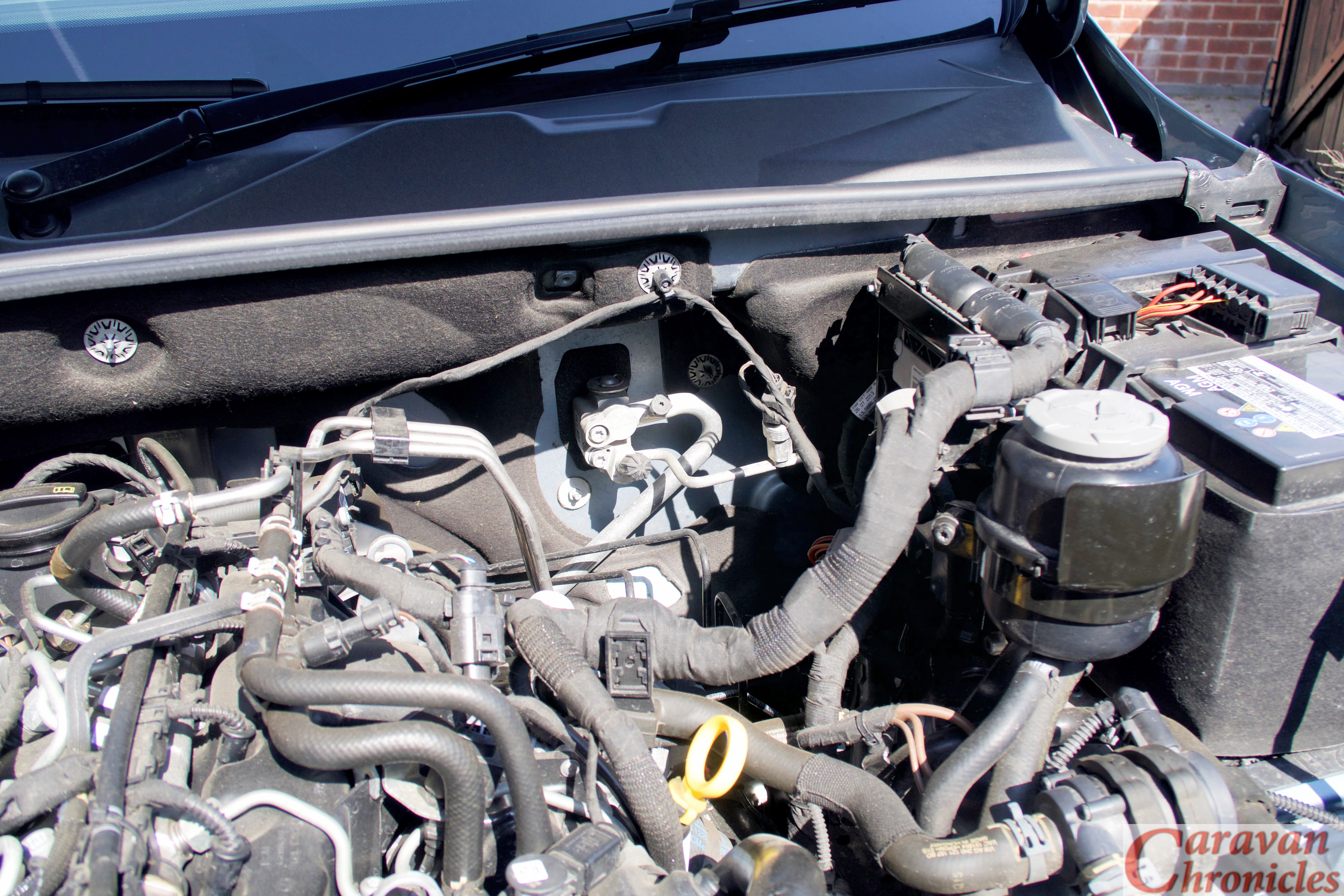
“When ever we have been away for a few days off grid on the return trip there always seems to be a strange smell coming from the engine compartment. We have a self converted T6 camper and 400Ah of AGM leisure batteries with 240 watts of solar on the roof. After watching a couple of YouTube installations of DC to DC chargers I recently installed a Redarc DC to DC charger to help keep the leisure batteries in good condition and fix some issues I was having with the smart alternator”.

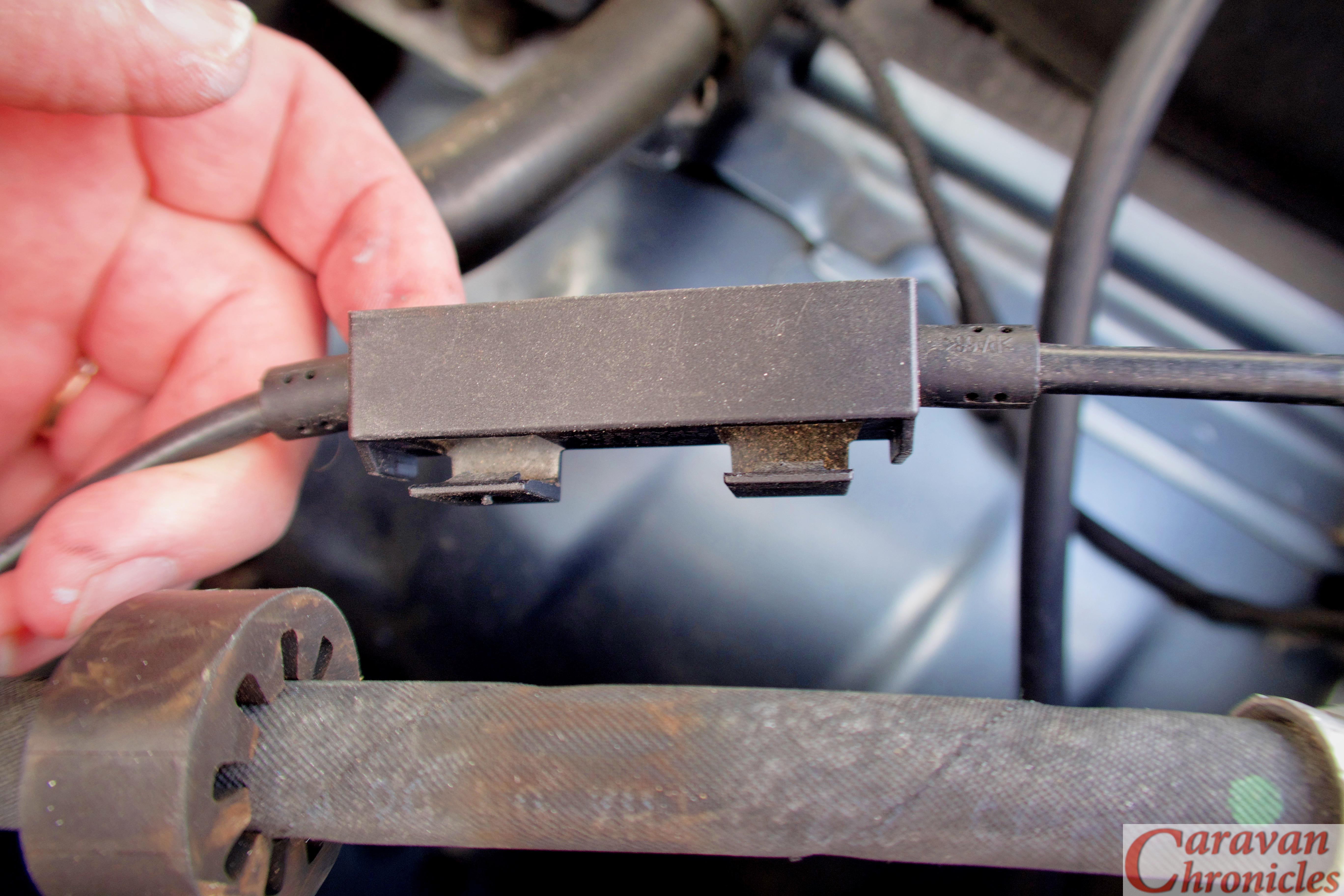
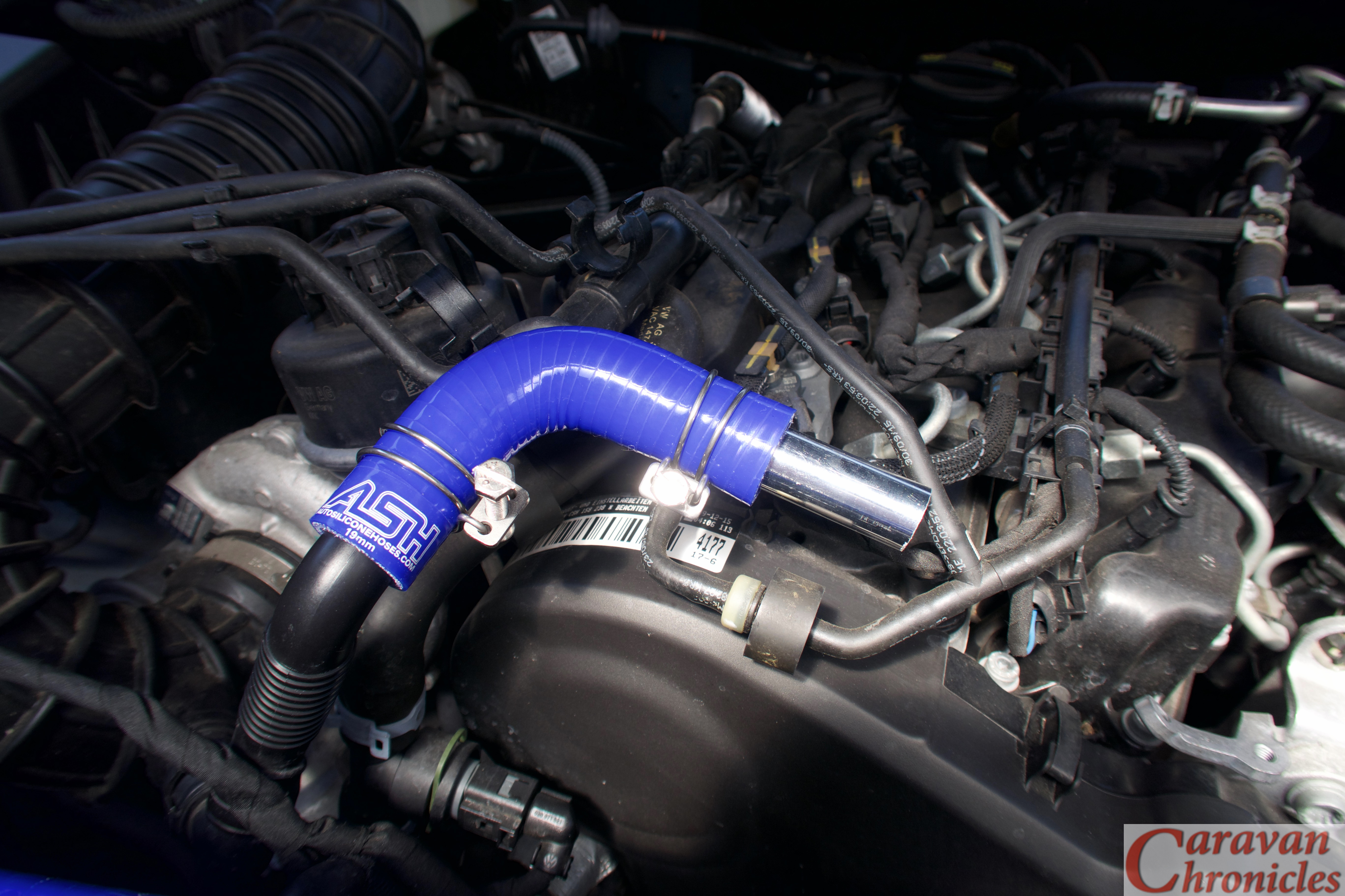
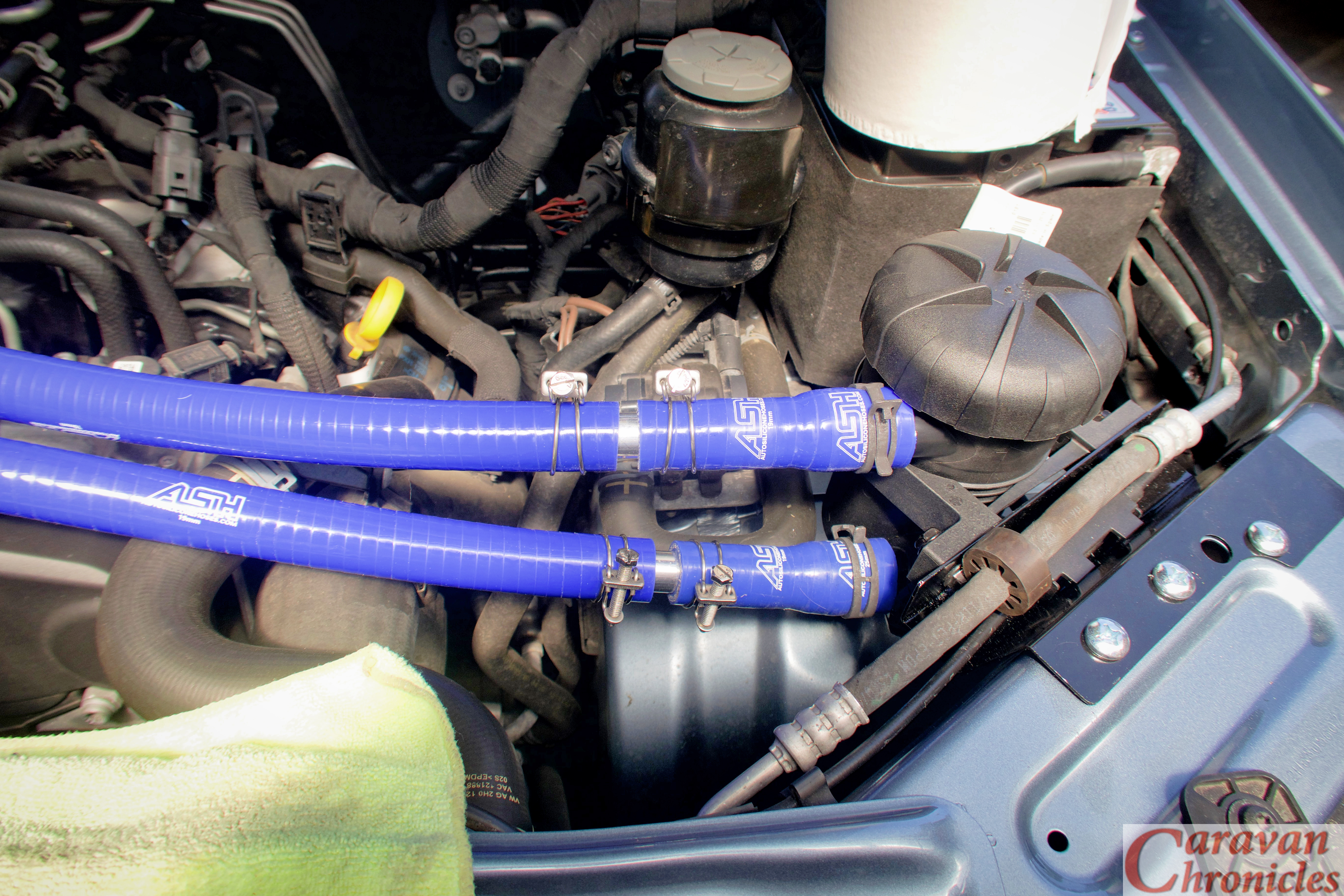
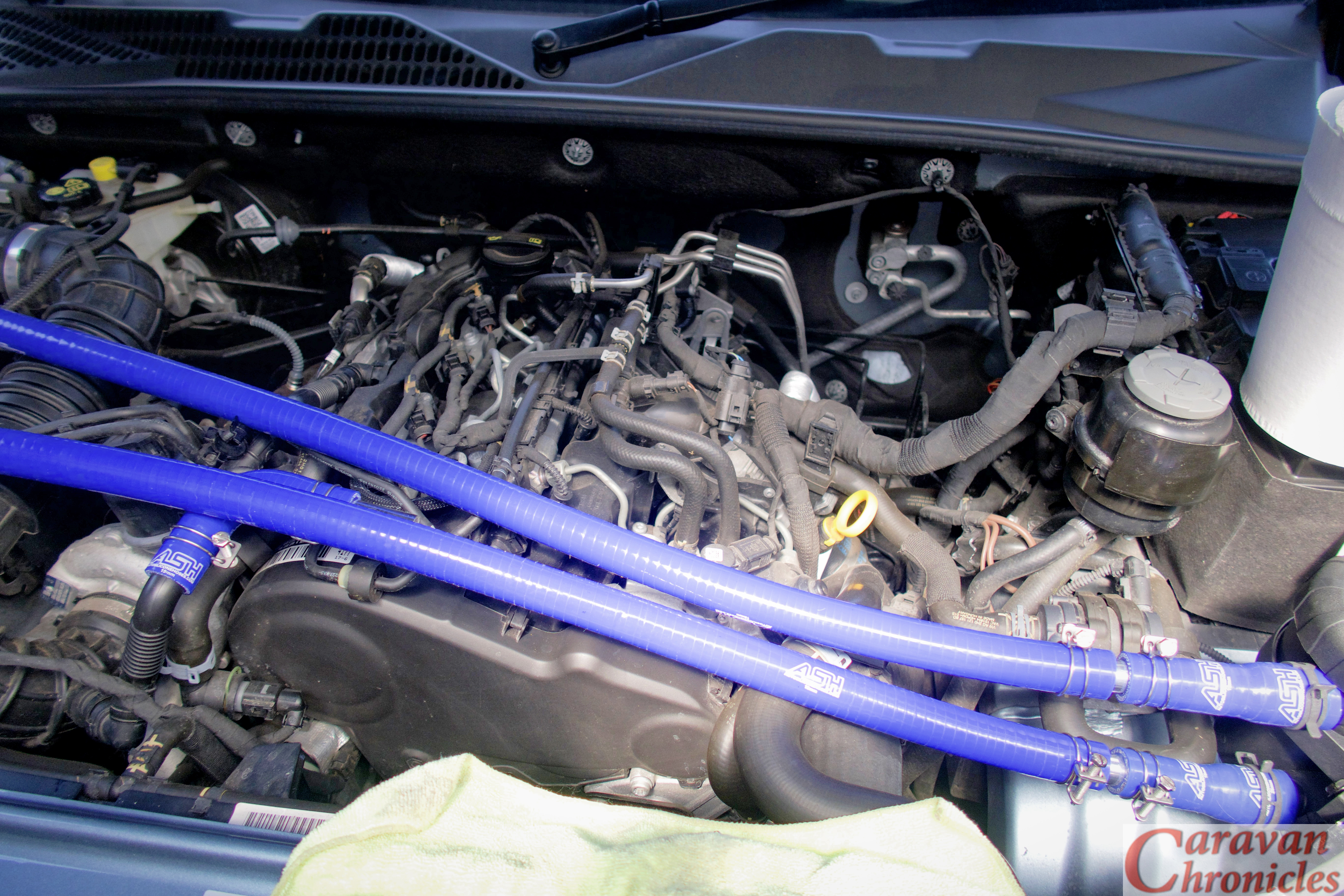
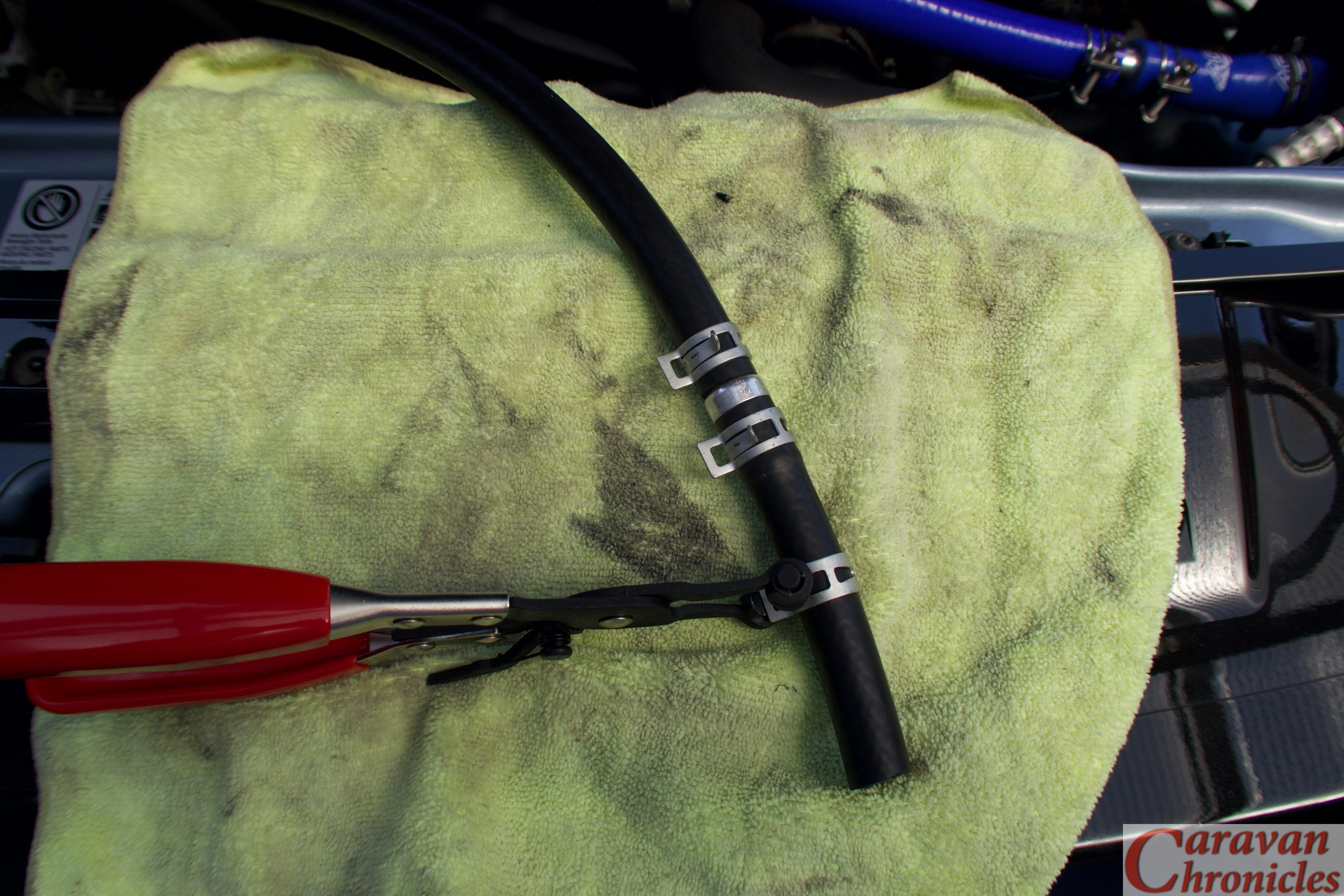
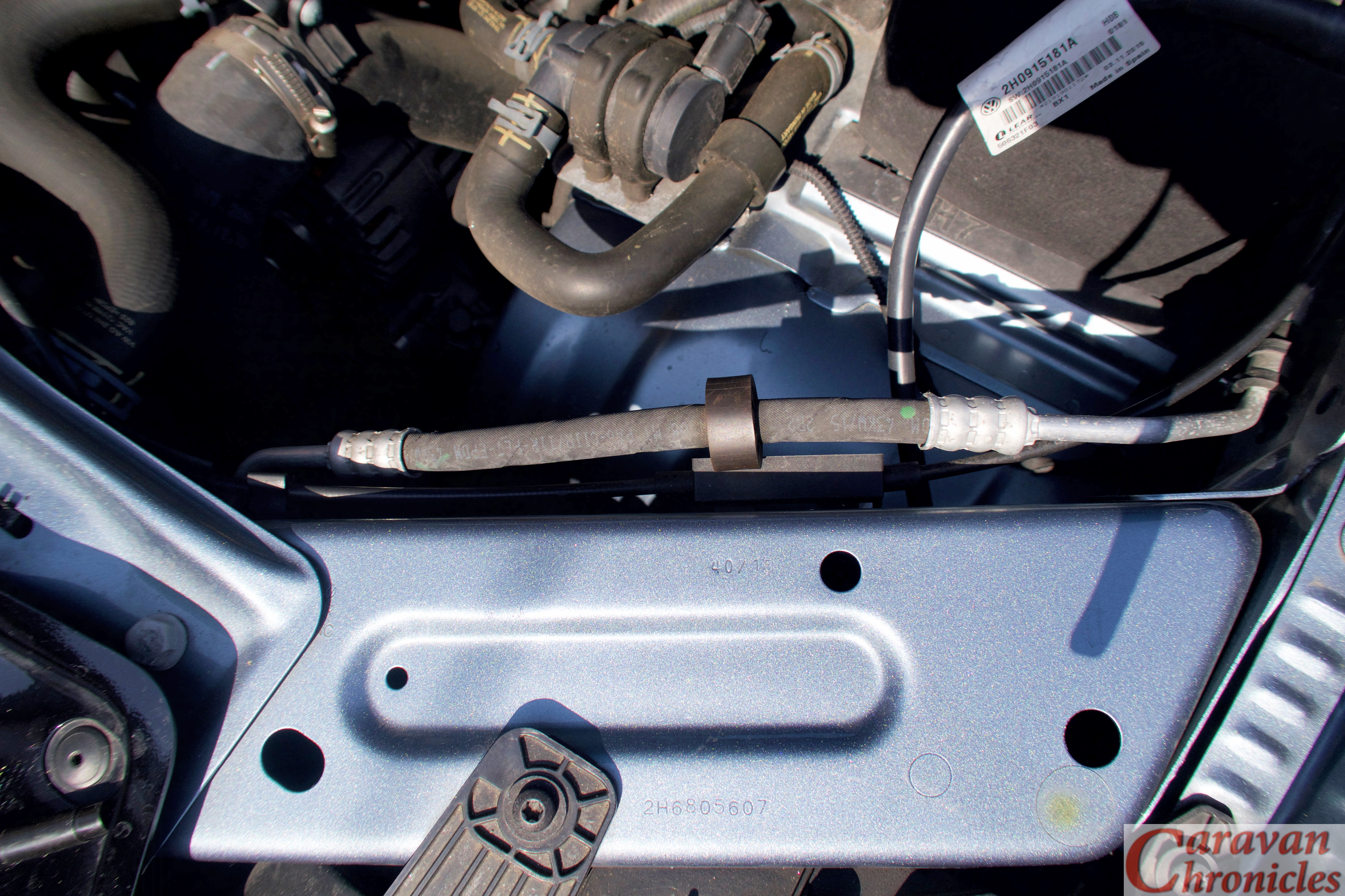
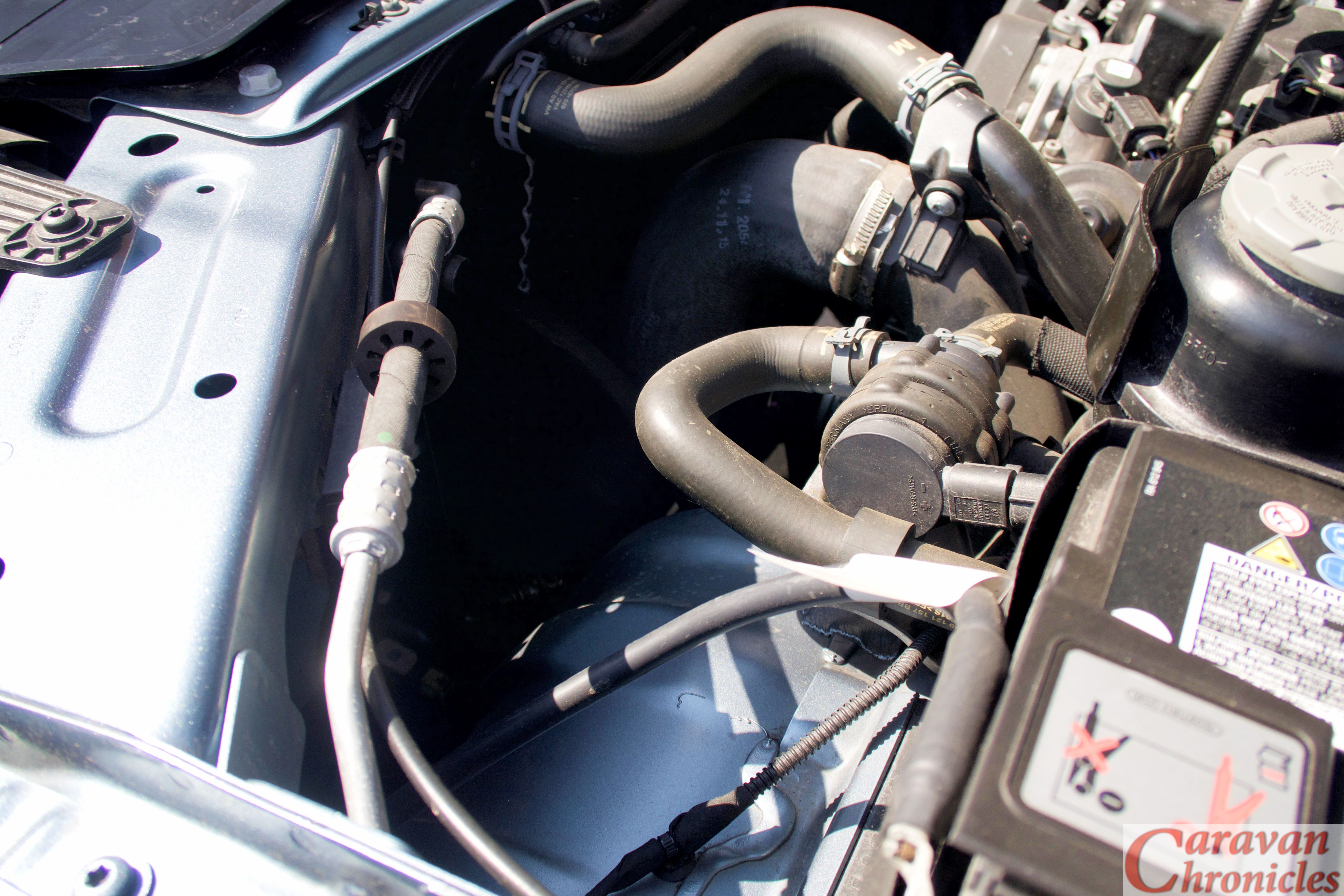
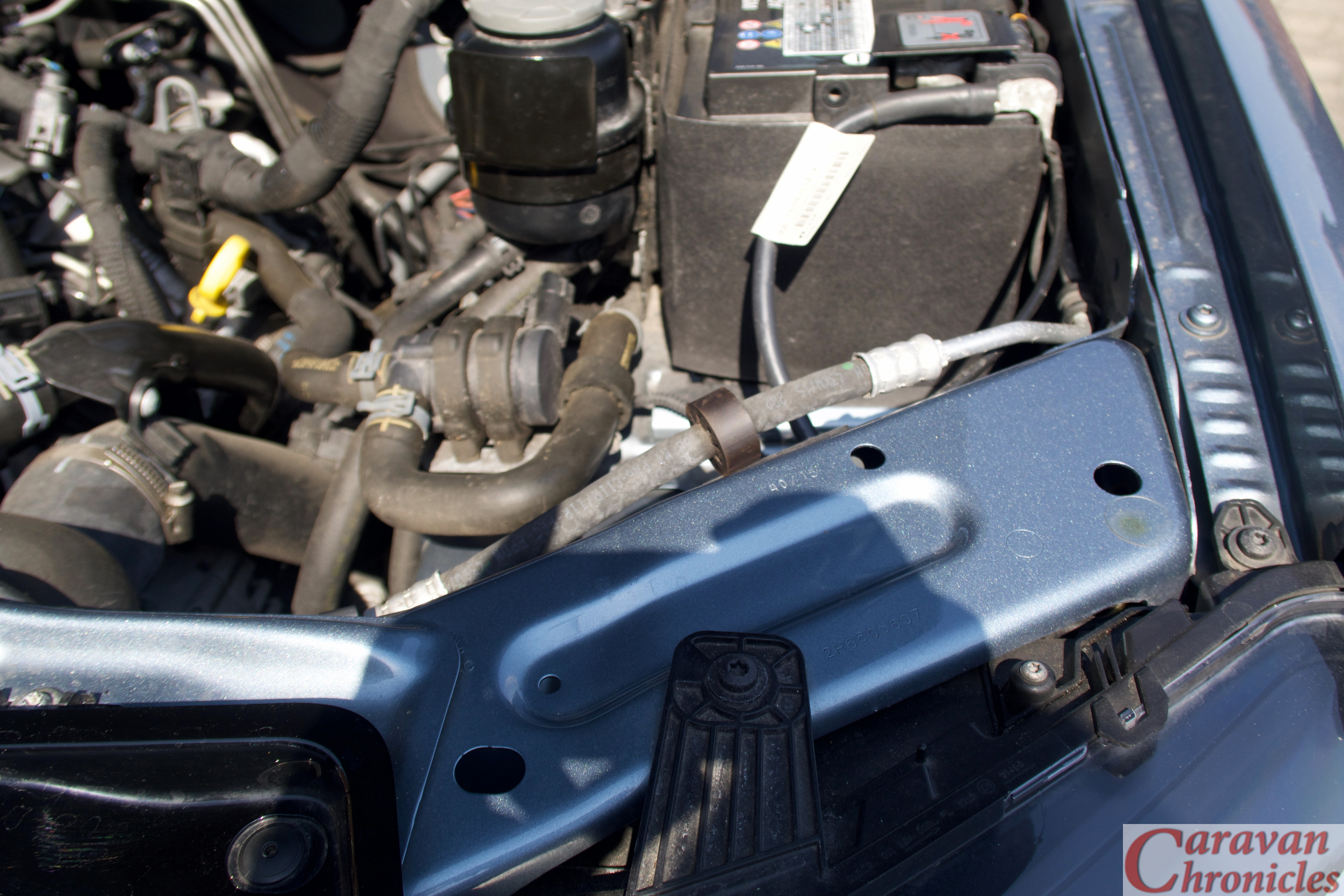
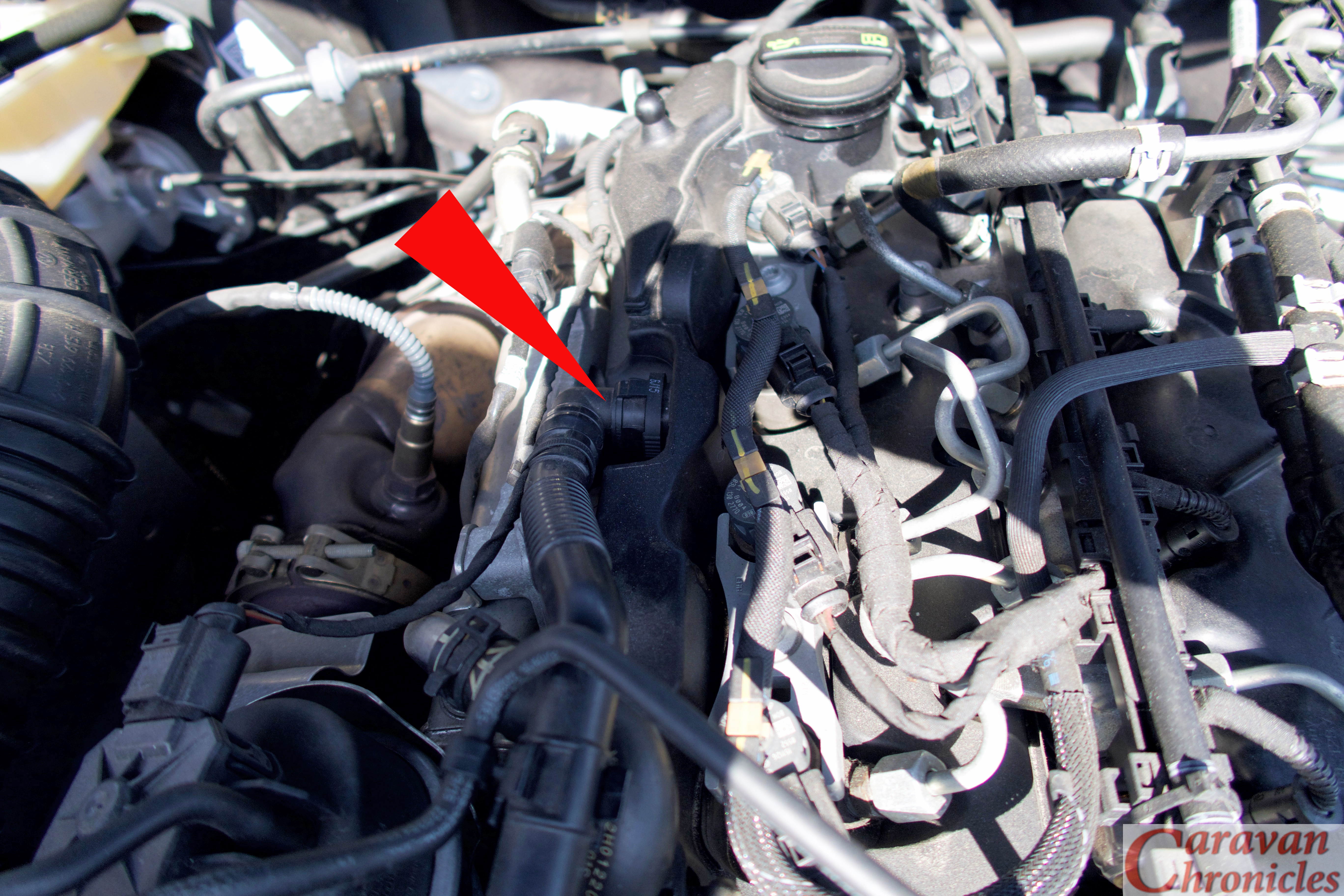
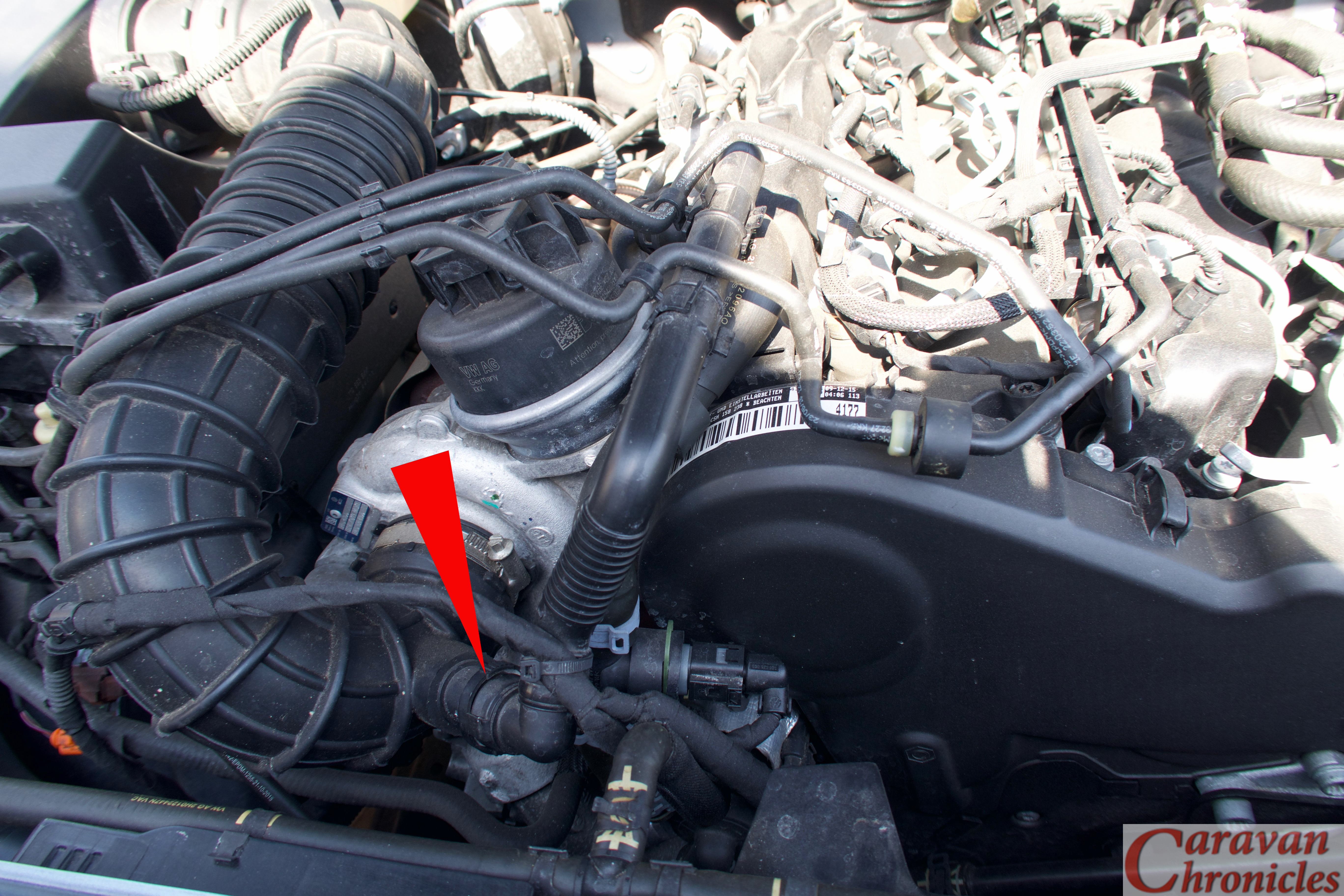
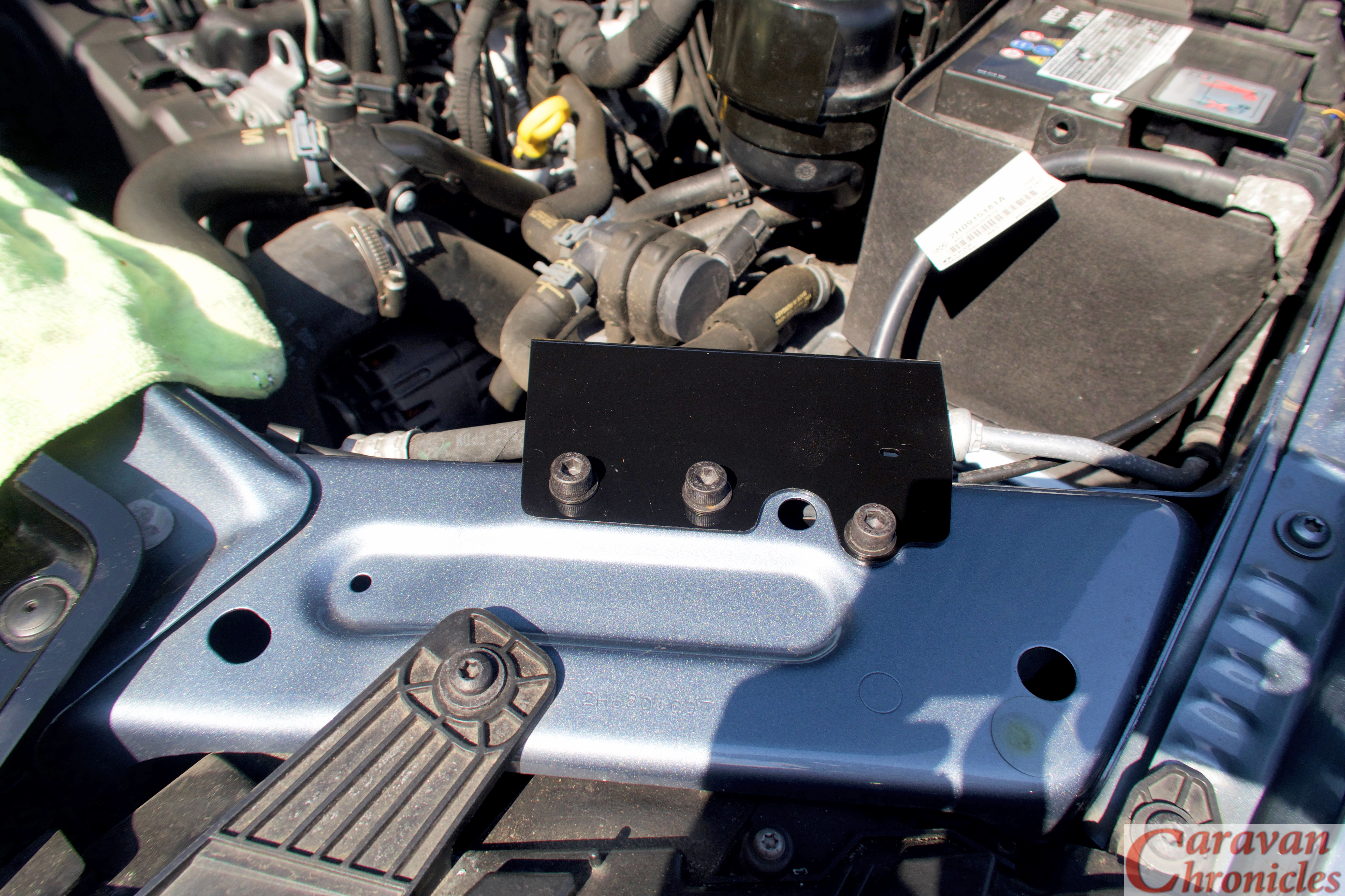
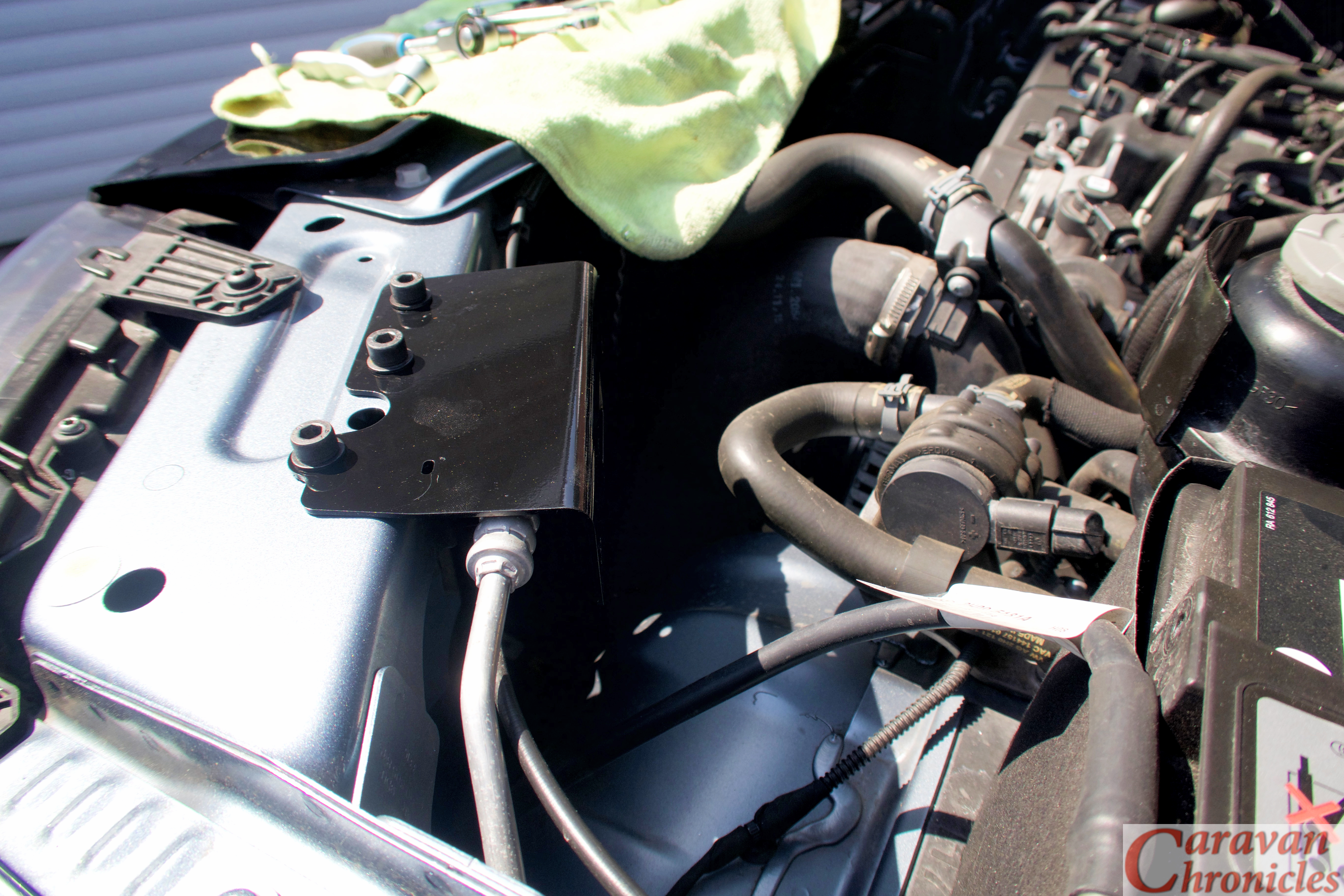
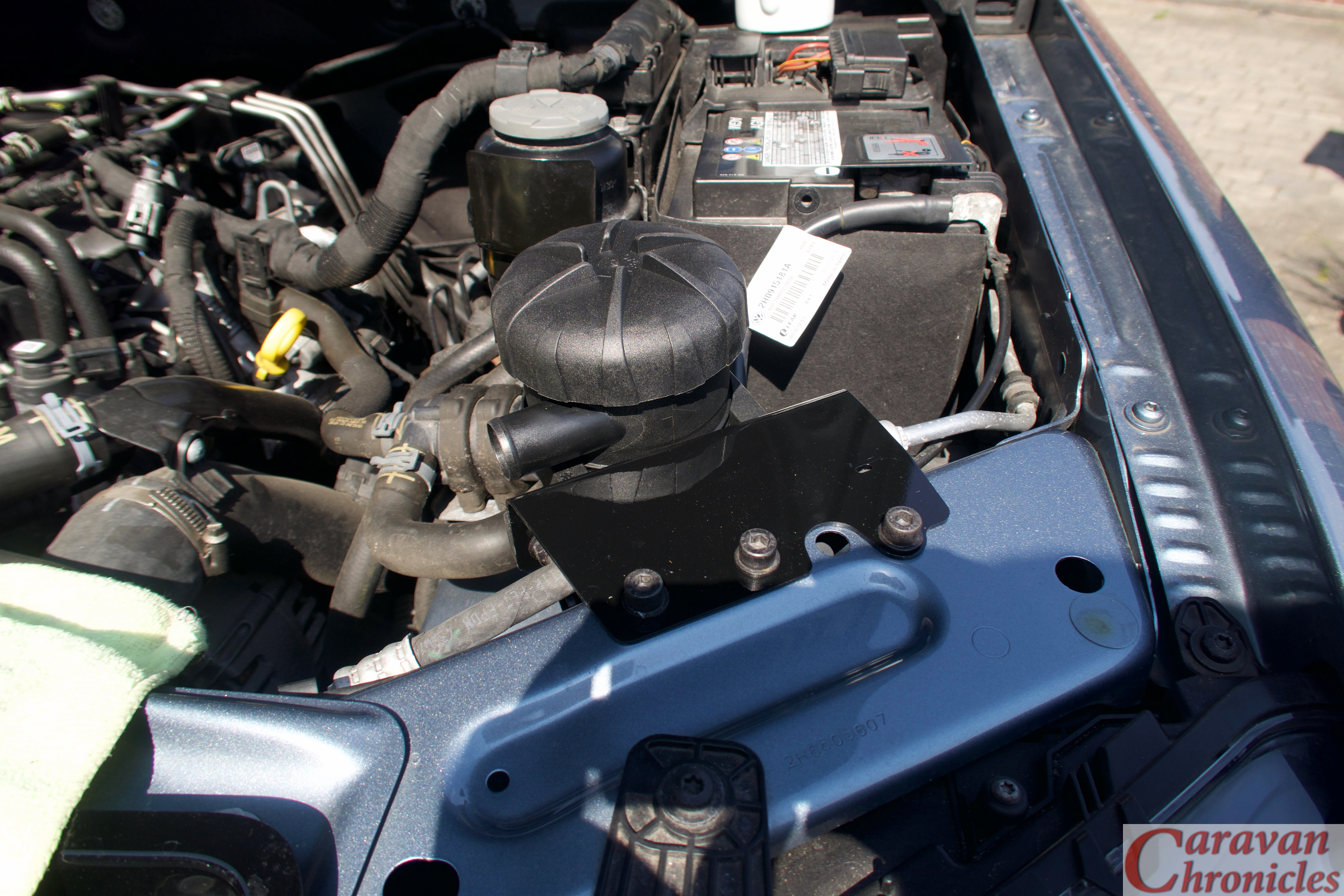
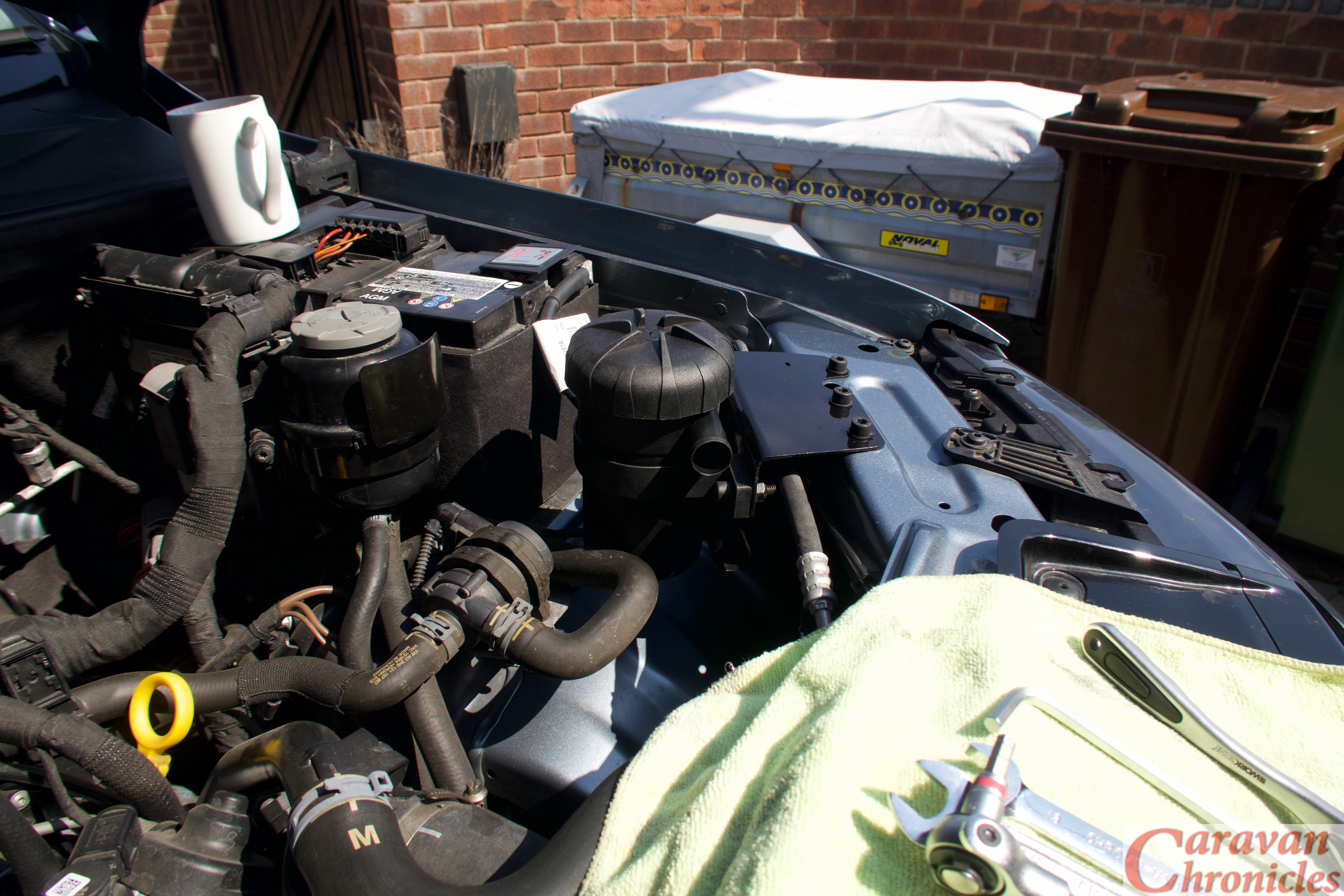
OK again after several email exchanges and a couple of video clips I got to the bottom of this one as well. The RedArc unit is capable of charing at 50 Amps and to do this pulls around 55 to 60 amps from the vehicles alternator. However there are a couple of issues in doing this. One of the first things that the Car Audio guys always recommend before installing any of the mahoosive bass pumping amps in vehicles is to replace and upgrade three essential cables. The first is the cable from the alternator output to the battery, the second which might not seem so obvious is the ‘earth strap’ as it is sometimes called from the engine to the vehicle chassis. This need either replacing completely with a larger cross section and also where it terminates on the vehicle needs altering. Usually the Audio boys install a new cable from the alternator mounting bolt directly back to the negative battery terminal*. Why” Well quite often the engine earth strap is just a simple copper braid strip sized just big enough so the starter motor current won’t burn it out for the 5 to 10 sends the starter is operated. You start trying to push the engine battery charing current and the additional 60 amps for the DC to DC charger through it, it starts to get warm. Not a problem as usually it’s not covered in a PVC jacket and hanging down in a bit of air flow under the engine. So the Audio guys change or upgrade it and they pull more current than we do. The third and last one that is upgraded is the short stubby battery negative lead going to the vehicle chassis. For our purposes, not really a necessity but hey ho.

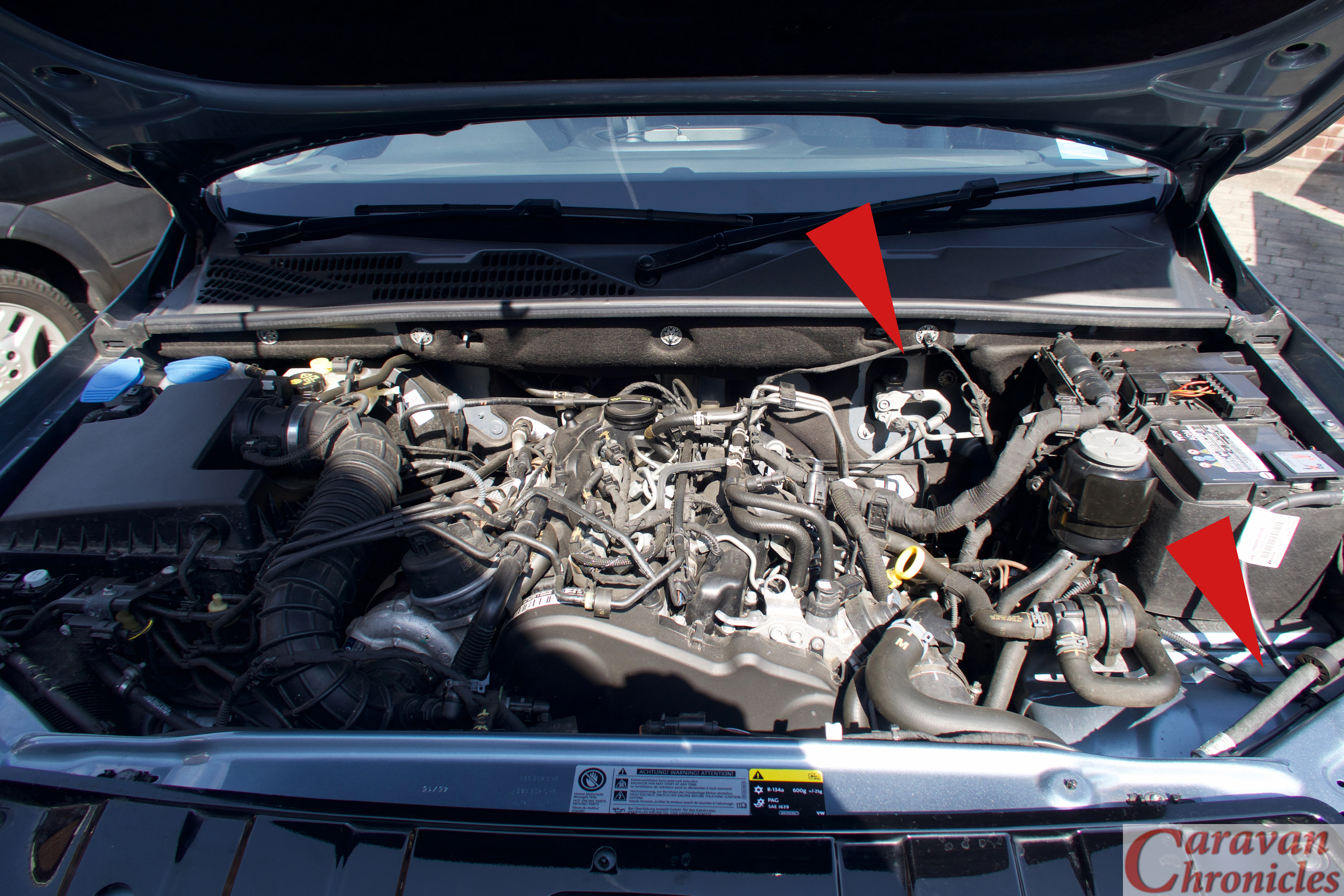
*A note of caution. On most vehicles now there is a shunt between the large negative cable going to the battery and the negative terminal of the battery. This allows the vehicle ECU to determine the current flow in and out of the battery. It is important that you only connect any ancillary equipment to the cable side of this shunt and not to the battery side. However some DC to DC chargers specify you connect to the battery side of the shunt. Please refer back to the instructions with your particular unit.

What was going on?

Well basically the negative side of the circuit was getting a bit warm and the lead from the alternator was running at virtually it’s maximum rating. What you have to remember is that the vehicles electrical system is really designed down to a price and to do just the job of keeping the vehicle running. As soon as you start to ask a bit more of it you are stressing some elements and you have to consider all aspects and upgrade parts sometimes.

Conclusion

Adding an additional earth strap from the alternator mount directly to the chassis side of the shunt on the negative post of the engine battery and upgrading the alternator positive cable made a big difference and there is no longer any smell after a couple of hours of charging from the engine. Apparently starting the diesel engine has been improved with the report: “it seems to turn over a lot faster when starting” so maybe there was an underlying issue with engine earthing somewhere?

My two cent’s….

  • Don’t use the vehicle chassis as a neutral return path for any additional equipment you install. Modern vehicles are not so much welded as bonded together and some have aluminium or plastic body panels. Additionally even the steel they are made from is not as good a conductor of electricity as copper. Leave the vehicle electrics to the vehicle body and install your own neutrals.
  • Don’t ‘ground’ the leisure battery to the vehicle body. Keep the leisure battery circuits isolated from the vehicle body. Run a suitably sized neutral cable directly from the leisure battery to the vehicle battery.
  • Don’t use leisure battery terminals as a place to connect everything. Use a proper terminal bus bar block for live and neutral connections. The only connection on your battery terminal should be the main conductor going to either a second battery or a bus bar terminal block. The only exception to this is for battery monitors!
  • Don’t assume the vehicle electrics are up to the job. Most vehicle electrics do the job they were designed to do and not much more. As soon as you start asking the alternator to charge another one or two 100Ah batteries you are ‘stressing the system’ to a greater or lesser extent. Some big 4 x 4’s can handle this, some smaller vans might not be able to. Consider what you are installing and think about how the vehicle will handle this and look to see if anything needs upgrading.
  • Know what cable terminations to use and where. Also don’t cheap out on the correct terminal installation tool. If you are building or converting a camper van is it worth saving £25 on a proper ratchet crimp tool?

Don’t watch someone on YouTube do something and assume that if you do it exactly the same way it’s going to be right. It’s interesting on how many times people make a video on wiring or installing equipment and follow it up with “if you want to know more go and watch so and so’s video about it. He produces really good videos how to do this” Just because someone produces really good videos doesn’t mean the videos show how to do something correctly. It’s only how they did it, not an installation bible. You have to do your own research and learn to sort out the good guides from the bad.

I have watched an awful lot of YouTube motorhome refits, camper van, step van and bus conversions etc and a lot of the electrical installation – especially on the 12 volt side is poor in my opinion. I’m not an expert however and I’ll only ever say how I’d so something and the rational behind why I’d do it that way.

Just throwing this out there to see if there is any interest….. I was thinking about doing either a small forum on the blog or a Q & A page as a resource for some of the electrical ramblings. Would that be of interest/use to anyone? I do know that quite a few of the electrical drawings I have done have been downloaded and again wondered if specific drawings for equipment would be useful. Let me know in the comments below.

  • Related posts you may like…
  • A Request…
  • Euro 6 Engines, Smart Alternators and Your Leisure Battery…
  • For Anyone Restoring A Vintage Caravan…
  • Overland Vehicle Electrics and Other Stuff…
  • A Quick Fault Finding Tip…
  • Something For Your Toolbox…
  • Getting All Charged Up – Update 2…
  • Is A Euro 6 Engine Killing Your Leisure Battery?…
  • Getting All Charged Up – Update
  • Getting All Charged Up – Part 3 “The Install”…
  • Getting All Charged Up – Part 2…
  • Getting All Charged Up – Part 1…
  • Smart Alternators: how they affect Caravans and Motorhomes….

Share this:

  • Click to share on X (Opens in new window) X
  • Click to share on Facebook (Opens in new window) Facebook
  • Click to share on Tumblr (Opens in new window) Tumblr
  • Click to share on Pocket (Opens in new window) Pocket
  • Click to share on Pinterest (Opens in new window) Pinterest
  • Click to share on Reddit (Opens in new window) Reddit
Like Loading...

Euro 6 Engines, Smart Alternators and Your Leisure Battery…

27 Saturday Jul 2019

Posted by Simon Barlow in Caravan Electrics, Electrical, Technical, Tow Vehicle, Uncategorized

≈ 49 Comments

Tags

Caravan Fridge, Caravan Fridge Problem, Euro6 Engines, Leisure Battery Charging, Smart Alternator

About 12 months ago I wrote a blog post “Is A Euro 6 Engine Killing Your Leisure Battery?” and it got a few comments and generated a number of emails. However 12 months on I’m getting a lot more questions relating to problems around smart alternators and I’ve brought forward this blog post by quite a few months from my planned posting date following a couple of long email exchanges with two readers and a few others.

Right, I think the best way to explain this is to set the stage so to speak.

Bob stores his brand new caravan at home and it is regularly plugged in to the house to run the internal battery charger and a dehumidifier. It’s got a new 110Ah AGM leisure battery and a new motor-mover fitted. The caravan is plugged in at least 24 hours before any trip to get the fridge down to temp prior to stocking it up. Bob also has a brand new car, Euro 6 diesel with a smart alternator. The car is a few months younger than the caravan and he’s never towed a caravan with this car. The tow bar and tow electrics were all fitted by the dealer (or dealers agents) prior to it being purchased. He did tow this caravan on 4 trips with his previous car, same make but 6 years older.

The caravan suitably prepped, fridge down to temperature and stocked. An early morning departure and six hour journey with a couple of stops to catch the Euro Shuttle over to France followed by a couple of hours driving in France to their first destination. On arriving, Bob sited the caravan on to the pitch not using the motor-mover and went about setting up. Mrs Bob knowing a request for a cup of tea was imminent went inside to put the kettle on where she discovered everything in the freezer had defrosted. Bob checked the fridge, it was still set for travelling. For what ever reason he also checked the leisure battery on the caravan’s system… 12.1 volts.

Over the next few days there was a couple of phone calls to their caravan dealer along with a number of emails. For the next three weeks and 2 other camp sites the fridge worked perfectly. On the return trip a similar distance and travelling time to the outward journey ended up when Bob returned home he only managed to get the caravan part way up the drive using the motor mover. He had to plug the caravan into his house overnight to charge the leisure battery enough to allow him to use the motor mover to finally put the caravan into its ‘home’ at the rear of the house.

Within a couple of weeks the caravan was returned to the dealer for extensive checking and the dealer could not find any issues with it or the fridge. They put forward the idea it must be an issue with the car. Bob tended to agree with this as he had taken this caravan on four trips towing with is old car and never had any issues. Three relatively short trips, the other a longer two week trip from the North East down to Cornwall, a similar 8 or 9 hour journey and everything seemed fine.

After a conversation with the main dealer who agreed to have the vehicle towing electrics checked over the next couple of days. The verdict from the main dealer was they could find nothing wrong with the vehicle, everything was working as expected.

Now, this is where I got involved. The above is actually an amalgamation of two very similar emails asking for thoughts and advice. The people involved had vehicles from different manufacturers and the caravans were also from different manufacturers. The only common element was the vehicles were new and had Euro 6 engines with smart alternators. I am not going to mention the vehicle or caravan manufacturers for a couple of reasons…. one, I don’t want to end up on the wrong end of a legal letter and two, I don’t actually think the manufacturer of either is relevant.

What’s Going On?

Luckily for me Bob is recently retired but knows his way round an AVO 8 being an apprentice TV repair man for Redifusion back in the day when valves were king. (Just as an aside, I bought my first AVO 8 back in 1976 and paid £8 for it. It was Ex REME in a leather case. I purchased it from MAZEL RADIO on London Rd in Manchester. Anyone from Manchester of a certain age will know Mazel Radio).

To cut a long story short over a period of a couple of weeks we proved that when hitched up, as soon as the smart alternator went into eco mode, there was a current flow up to about 4.5 to 5 amps FROM the leisure battery TO the car. This only stopped and reversed when the electrical load in the car caused the vehicles ECU to turn on the alternator’s output. Furthermore we determined that with the caravan hitched up, the period the alternator was in eco mode was also longer than when unhitched. Although we could not prove this with definitive evidence, this would also support the reverse current flow from the caravan to the vehicle that we were seeing as the caravan leisure battery was now supporting the vehicle battery.

Now there were a few questions that were buzzing round my brain….

  • Why didn’t the caravan habitation relay drop out when the smart alternator went into eco mode to stop this reverse flow?
  • Why didn’t the dedicated tow electrics strop this reverse flow?
  • Why didn’t the vehicle ECU knowing a trailer was hitched stop the alternator going into ECO mode?
  • If the ECU put the alternator into eco mode why didn’t it drop the fridge supply and by default release the habitation relay?
  • Why did the fridge defrost/not work even though in theory there was a voltage supplied to it?
  • Was this the reason I had seen an increase in emails relating to motor mover issues and batteries not holding their charge?

What Next?

I don’t really know. I don’t know how wide spread an issue it is or its going to become. I also don’t know the details of how specific manufacturers implement eco modes in the ECU programming or how the tow bar electrical interface manufacturers could work round the potential issues while still being able to get their products certified by vehicle manufacturers.

I think it might be down to the caravan manufacturers to come up with a solution. I know that there are a couple of after-market products available that provide a solution – We have one I installed in our caravan and in the short term I think this will be the quickest route. Caravan manufacturers may have a reluctance to respond and they can legitimately say “Well it is designed to work correctly to the relevant standards.” I think that maybe it will require the two main caravan clubs to look further into this and if what I have outlined above is proven by them to be the case, bring pressure to bear on all the parties concerned to come up with a way forward to resolve the issue.

For my part, I have contacted a few manufacturers asking for information and clarification or even acknowledgement of an issue. Unfortunately no one seems to want to talk about it. I do know individuals have emails details of their own problem to manufacturers and have received less than helpful responses.

Let me know in the comments below if you have had anything that might be related to this. I’d like to find out more.

EDIT:…

The thought just crossed my mind…. what affect, if any, will this have on AL-KO ATC (if fitted) when the vehicle is in eco mode and the alternator shut down? Does is mean that there is a possibility that the AK-KO ATC may not work correctly in all circumstances?

  • Related posts you may like…
  • The problem with information from the internet…
  • A Request…
  • For Anyone Restoring A Vintage Caravan…
  • Overland Vehicle Electrics and Other Stuff…
  • A Quick Fault Finding Tip…
  • Something For Your Toolbox…
  • Getting All Charged Up – Update 2…
  • Is A Euro 6 Engine Killing Your Leisure Battery?…
  • Getting All Charged Up – Update
  • Getting All Charged Up – Part 3 “The Install”…
  • Getting All Charged Up – Part 2…
  • Getting All Charged Up – Part 1…
  • Smart Alternators: how they affect Caravans and Motorhomes….

Share this:

  • Click to share on X (Opens in new window) X
  • Click to share on Facebook (Opens in new window) Facebook
  • Click to share on Tumblr (Opens in new window) Tumblr
  • Click to share on Pocket (Opens in new window) Pocket
  • Click to share on Pinterest (Opens in new window) Pinterest
  • Click to share on Reddit (Opens in new window) Reddit
Like Loading...

For Anyone Restoring A Vintage Caravan…

04 Thursday Jul 2019

Posted by Simon Barlow in Caravan Electrics, Caravan Restoration, General, Modifications, Technical

≈ 10 Comments

Tags

Caravan Electrics, Caravan Restoration, Vintage Caravans

A short while ago two people contacted me separately asking if I had any information relating to rewiring restoration caravans so that they could plug into a modern 13 pin electrics tow car and take advantage of leisure battery charging and run a modern fridge or coolbox.

This was followed up be someone asking me how they could upgrade a late 1970’s caravan and still incorporate and use the “CAR-VAN” switch to change between using the leisure battery or vehicle battery.

Wiring diagram showing how to wire a vintage caravan to modern tow vehicle electrics

I came up with a couple of drawings that covered the basics to show how they could be upgraded to modern tow vehicles. The one above is a basic ‘front end’ from 13 pin plug back to a fuse block for the road lights and a habitation relay.

The drawing below add in the option of a “CAR-VAN” switch (sometimes labeled as CAR-CARAVAN) which uses the same 40 Amp relay as the habitation relay rather than a chunky high amp switch found in some models. However installing a CAR-VAN switch does have limitations… for example you could not install an inverter.

Wiring diagram showing how to wire a vintage caravan to modern tow vehicle electrics with the traditional CAR-VAN switch

If you want to download these drawings (or any others I have done recently) they are now in PDF format sized A3 and can all be found on the “Electrical Drawings” sub menu below “Document Library“. I kept getting emails asking where such and such a drawing was, so I decided to put them all into one place.

I don’t normally do electrical drawings for specific projects (unless being paid), however if you have something that you think might be of interest to a wider audience drop me an email.

  • Related posts you may like…
  • A Request…
  • The problem with information from the internet…
  • Euro 6 Engines, Smart Alternators and Your Leisure Battery…
  • For Anyone Restoring A Vintage Caravan…
  • Overland Vehicle Electrics and Other Stuff…
  • A Quick Fault Finding Tip…
  • Something For Your Toolbox…
  • Getting All Charged Up – Update 2…
  • Is A Euro 6 Engine Killing Your Leisure Battery?…
  • Getting All Charged Up – Update
  • Getting All Charged Up – Part 3 “The Install”…
  • Getting All Charged Up – Part 2…
  • Getting All Charged Up – Part 1…
  • Smart Alternators: how they affect Caravans and Motorhomes….

Share this:

  • Click to share on X (Opens in new window) X
  • Click to share on Facebook (Opens in new window) Facebook
  • Click to share on Tumblr (Opens in new window) Tumblr
  • Click to share on Pocket (Opens in new window) Pocket
  • Click to share on Pinterest (Opens in new window) Pinterest
  • Click to share on Reddit (Opens in new window) Reddit
Like Loading...

Something For Your Toolbox…

03 Wednesday Apr 2019

Posted by Simon Barlow in Caravan Electrical Fault Finding, Caravan Electrics, Caravan Fault Finding, Electrical, Maintenance, Technical

≈ 7 Comments

Tags

Earth Side Testing, Electrical Fault Finding, Technical

A few weeks ago I posted a blog post called “A Quick Fault Finding Tip…” and that  generated quite a few emails regarding electrical testing and how to trace faults.  In fact a lot of the other electrical posts I’ve done over the years still generate emails and comments (it’s always worth checkingback on some of th eolder posts to read the comments) I’m going to try to explain a technique that’s really handy to have in your tool box for general fault-finding.

Earth Side Testing

Most people who perform general maintenance on their vehicle, motor home or caravan will be familiar with checking the voltage of the vehicle or leisure battery using a multimeter. Great little things to have and personally I think everyone should be able to do the basics with one.  So as a bit of a refresher I’ll go through this scenario with you. Checking the lights on your tow vehicle you notice one of the brake lights is a lot dimmer than the other. Let’s find out why. I’m going to simplify the circuit a bit it should give you the idea behind the principle.

Depending on the device you re reading this on the drawings might be small. If you want to see the drawing full size just click on it to open it up full size.

Earth Side Testing 1-0

In the drawing above you can see the basic circuit. The positive lead from the battery goes through the ignition switch and on to a fuse. From there through a connector to the brake pedal switch and on to another wiring loom connector to the back of the vehicle. It passes through another connector before arriving at the brake bulb holder. The holder is connected to the vehicle chassis via another wiring loom connector. The vehicle chassis is connected back to the battery in the engine bay. You can see we’ve checked the battery voltage with out meter and it reads 12.68 volts… so not a flat battery. We’ll make a note of the battery voltage.

OK… so the problem is this bulb  is not at full brightness.. so it’s got to be a loss of voltage supplying it somewhere in the circuit. We need to check the voltage along the circuit with the bulb lit (circuit live) and the black negative lead of our multimeter attached the battery negative terminal. (I’ll explain how to do this later).

Earth Side Testing 1-1

Probably the next place to check it would be the fuse… 12.66 volts, not too bad only 0.02 or 20 mV loss… lets keep going….

Earth Side Testing 1-2

..next is a wiring loom connector, back probing it gives a 10 Mv drop (loss) normally these modern connectors are pretty good.

Earth Side Testing 1-3

Brake light switch… Hmm a bit more of a drop… maybe a quick spritz with contact cleaner will sort that…

Earth Side Testing 1-4

Back probing the next connector gives a bit more of a loss… I’ll come back and check the brake light switch connector.

Earth Side Testing 1-5

OK, now at the back of the vehicle and a bit more of a drop at that connector but nothing too much…

Earth Side Testing 1-6

Well 12.13 volts on the bulb contact… so between the battery and bulb positive tip a total loss of 0.55 V or 550 mV…. that’s about within limits as I would not expect to see much more than a 500 mV… half a volt drop on a typical circuit like that. So what’s going on? A 500 mV drop can’t account for the dim bulb?

However, if we keep going and measure the voltage on the earth side of the bulb holder….

Earth Side Testing 1-7

Hang on we see a reading of 2.67 volts. How can that be? We are connected to ground at both ends of the meters test leads? A circuit has two sides, the positive side to the load – in this case the bulb and the return or negative side back to the battery.

Just because the negative wire on the bulb holder is only short and goes to a bolt securing it and maybe many others to the chassis doesn’t mean we can assume it is the same as being clamped to the negative battery terminal.

A few things to ponder…. vehicles are made of steel… steel is not as good conductor of electricity as copper… nether is aluminium that some vehicles have in their construction. At one time steel panels were all spot welded together… now a lot are bonded on with specialist adhesives. The earth point may well be in the boot or under the floor and will be subject to corrosion as will the main battery neutral cable in the engine bay. All this can compromise an electrical path back to the battery.

If we look at the voltage drop on both sides of the circuit we have 0.55 volts on the supply added to 2.67 volts on the neutral side…. 3.22 volts in total, so we are trying to light our bulb with only 9.46 volts.

Could we have got there quicker?

One of the checks I always do first with the ignition on is the battery voltage check to get a reference to work with and then simply move my red positive test lead over to some main point on the engine block….

Earth Side Testing 1-8

If I get a reading of more than 0.4 volts (400 mV) obviously my negative return path from the vehicle chassis is compromised. Time to turn everything off and undo the main earth cables to the chassis and engine and give them and the mounting points a good clean with scotch bright or fine emery and a dab of specialist grease (see “Shopping” below) to protect them from further corrosion.

In the scenario we have just gone through, I’ll bet a wet weekend in Blackpool that cleaning both the earth terminal at the back of the vehicle and the battery earth to the chassis would have sorted the problem. I’d also have a look at the brake pedal switch as there is a bit more of a voltage drop than I’d like. Most likely it’s the connector rather than the switch itself.

For those that tow…

Nearly all tow bar wiring looms will ground to the same point in the back of the vehicle with some of the other assorted vehicle earth cables…. installers take the easy route and if there are already cables earthed there … then another couple won’t make a difference.

This can and will have an effect on the performance of your caravan electrics. Both the leisure battery charging circuit and fridge circuit will probably be earthed at that point.. So in the case of the fault above, each of those circuits will have a voltage drop of 2.67 volts. Therefore if you have leisure battery charing or fridge issues its possibly not the wiring in the caravan,  it could be the wiring in the vehicle. Check the ground path first.

One quick check is with lights and ignition turned on, do a volt drop test between the battery negative terminal and one of the cable secured under the earth point at the rear of the vehicle where the tow pack electrics are terminated. If it’s above 0.5 V (500 mV) then give the earth points a clean.

One bit of advice I’ve given to people in the past is to run a 4mm or 6mm cable directly from the negative battery terminal to the back of the vehicle and terminate it at the earth point where all the rear lights and tow electrics terminate. Makes a heck of a difference.

Back Probing…

Frankie-Howerd

Right…. Franky Howard fans stop it now! Back Probing, you might have heard of it and really it’s nothing special. It’s a simple technique used when fault-finding and involves using a fine probe to get into the back of the connector where the cable enters to test the voltage without disconnecting the connector. Sometimes you can get away with a straightened paperclip wound round the tip of the multimeter test lead. You can buy test lead accessory packs that have various attachments or ‘caps’ that fit on the end of your test leads to make the task easier.

Screenshot 2019-04-03 at 11.11.25

How do I test between the battery and some other point on the vehicle or caravan?

I have made a few of these over the years… basically it’s a long length of wire, about 20 feet with a battery terminal sized crocodile clip at one end and a small crocodile clip at the other… and I don’t know how many I’ve given away to people. I have a couple, one long enough to get tot he back of the vehicle and one long enough to get to the back of the caravan when its hooked up to the vehicle. SImply clip one end to the battery negative terminal and the other to the negative lead on your multimeter. Often its an idea to tie a loose knot in the two leads to stop them coming apart. Caution though, this lead is connected to the ground side of the battery – don’t let it dangle where it might touch something… put a bit of tape for protection around the connection if required.

Shopping…

Multimeters…. a person can never have enough multimeters…. and since the demise of Maplin a couple of great places to keep an eye on is Aldi and Lidl. I got a couple of great general purpose multimeters from Aldi for £9 each. Not always available as they generally come up as special buy’s. However if you are an Amazon shopper then this https://amzn.to/2I91q91 seems like a great little multimeter with a lot of positive reviews for £12

I use Liqui Moli 3140 Battery Clamp Grease – https://amzn.to/2Vn0qSo for battery and chassis terminals. It’s a small tube but does last a while.

If you want to make your own long test lead this box of crocodile clips https://amzn.to/2VedU32 for about £4.50 is always handy.

A dream test tool…

If you are into testing or it’s part of your job then there has been something on the market for a while called “Power Probe” Now while the original is obscenely expensive and there are a number of copies out there. The Auto Power scan PS100 is priced at about £80 and does the job in one simple instrument – https://amzn.to/2OJHYAW (Any sponsors out there… hello….hello…) This is on my “I really want one of those” list!

Finally…

"Oscar" our senior safety cat.

As always when working on anything electrical think safety. Oscar our Health & Safety Cat would like to remind you that working on vehicle electrics can be just as dangerous as working on house electrics. If you are unsure then DON’T…. get in touch with someone who is qualified. Find the right person and they will usually help you to do it safely. Be like Oscar – Be Safe.

  • Related posts you may like…
  • A Request…
  • The problem with information from the internet…
  • Euro 6 Engines, Smart Alternators and Your Leisure Battery…
  • For Anyone Restoring A Vintage Caravan…
  • Overland Vehicle Electrics and Other Stuff…
  • A Quick Fault Finding Tip…
  • Something For Your Toolbox…
  • Getting All Charged Up – Update 2…
  • Is A Euro 6 Engine Killing Your Leisure Battery?…
  • Getting All Charged Up – Update
  • Getting All Charged Up – Part 3 “The Install”…
  • Getting All Charged Up – Part 2…
  • Getting All Charged Up – Part 1…
  • Smart Alternators: how they affect Caravans and Motorhomes….

Share this:

  • Click to share on X (Opens in new window) X
  • Click to share on Facebook (Opens in new window) Facebook
  • Click to share on Tumblr (Opens in new window) Tumblr
  • Click to share on Pocket (Opens in new window) Pocket
  • Click to share on Pinterest (Opens in new window) Pinterest
  • Click to share on Reddit (Opens in new window) Reddit
Like Loading...

A Request…

09 Sunday Dec 2018

Posted by Simon Barlow in Blog updates, Caravan Electrical Fault Finding, Caravan Electrics, Caravan Fault Finding, Caravan Servicing, Electrical, General, Help Guides, Maintenance, Motor Home, Technical

≈ 11 Comments

Tags

Fuse Voltage Drop Table, Relay Wall Chart, Technical, Wire Size Chart

Ok, not one of my usual blog posts. I get a lot of email asking about various electrical items related to caravans and motorhomes and a few things seem to keep cropping up on a regular basis. One is to do with 12 volt relays… what types are there and what are the pin connections.

Another is to do with cable size relating to load and its relation to the length of cable…. “I have a 40 Amp load and its 3 metres from the battery… what size cable do I need?” type questions.

In the past I’ve emailed back with answers, but one caravan engineer asked me if I know of any information sheets that had this type of info that he could put above his workbench.

So I’ve produced a couple of A3 size PDF information sheets (they will print A4) that can be downloaded printed out and pinned up, shoved in your notebook, glued to the lid of your tool box or used to wrap that must have tool present for your beloved caravan or motorhome DIY enthusiast in your life (seasonal eh!)

(I have been told that Office World can print and laminate A3 PDF’s cheaply…. I never knew that!)

Screenshot 2018-12-09 at 10.23.41

Click here to download the  Relay Wall Chart

Screenshot 2018-12-09 at 10.24.11

Click here to download the   Wire Size Wall Chart

Screenshot 2018-10-11 at 16.52.54

Click here to download the Fuse Voltage Drop Table

I have stylised them as technical drawings and I’ve had to watermark them and some of the icons as I found a lot of my drawings were ending up “as is” or edited on various sites and forums without any credit or link back to Caravan Chronicles. You are free to print out and use them for your own personal use, but if you wish to use them (or any of my drawings) for commercial use, inclusion in blog posts or forums please include a credit line back to CaravanChronicles.com and drop me a line to let me know.

We are just back from Chester Fairoaks after doing the Chester Christmas market and a bit of shopping at Cheshire Oaks Designer Outlet Village and will be adding off to York for a bit more Christmas Market action.

I have a couple of more information ‘posters’ in development but if you have any ideas for future offerings, drop a line in the comments below. Of course my legal advisor – Henry has asked me to point out E & OE

(Everything on the internet is improved by a cat apparently… so here’s Henry)

IMG_2176
  • Related posts you may like…
  • A Request…
  • The problem with information from the internet…
  • Euro 6 Engines, Smart Alternators and Your Leisure Battery…
  • For Anyone Restoring A Vintage Caravan…
  • Overland Vehicle Electrics and Other Stuff…
  • A Quick Fault Finding Tip…
  • Something For Your Toolbox…
  • Getting All Charged Up – Update 2…
  • Is A Euro 6 Engine Killing Your Leisure Battery?…
  • Getting All Charged Up – Update
  • Getting All Charged Up – Part 3 “The Install”…
  • Getting All Charged Up – Part 2…
  • Getting All Charged Up – Part 1…
  • Smart Alternators: how they affect Caravans and Motorhomes….

Share this:

  • Click to share on X (Opens in new window) X
  • Click to share on Facebook (Opens in new window) Facebook
  • Click to share on Tumblr (Opens in new window) Tumblr
  • Click to share on Pocket (Opens in new window) Pocket
  • Click to share on Pinterest (Opens in new window) Pinterest
  • Click to share on Reddit (Opens in new window) Reddit
Like Loading...

A Quick Fault Finding Tip…

12 Friday Oct 2018

Posted by Simon Barlow in Caravan Electrical Fault Finding, Caravan Electrics, Caravan Fault Finding, Caravan Servicing, Electrical, Technical, Tips

≈ 18 Comments

Tags

Caravan Electrical, Fault Finding, Maintenance, Technical, Tips

Sometimes things you take for granted and have in your toolbox of fault-finding tricks are a dark art to others.

I was talking someone through a bit of fault-finding on their vehicle and asked if they had measured the current in the circuit. “No” came back the answer. I asked what type of fuse and rating it was and asked the person to just put their voltmeter across the fuse and tell me the voltage across the fuse. “Ah… that’s about 3.2 amps then” I said.

“How do you know that?”

Simple really – all fuses have a resistance and if you know that you can work out the current from the voltage drop. Even simpler really – there are tables for various fuses that have it all worked out for you. I have a selection collected over the years stuffed into the lid of my tool box, along with a lot of other junk paperwork!

I created a volt drop table based on PEC (Pacific Engineering Corporation) fuses that are supplied as OEM fuses in most Japanese, Korean and European vehicles however it is pretty accurate for almost all other makes of the same type of fuse. I printed mine out, laminated them and added them to the collection in the top of my toolbox.

Screenshot 2018-10-11 at 16.52.54

It’s quite easy to use. Just set your multimeter to read DC mV and read the voltage displayed. Now select the fuse type, in this case an ATO fuse – the most common used in vehicles, caravans and motorhomes and from the chart look down the left column until you see the voltage measurement that matches the one on your multimeter… lets say 0.011 volts (11mV)

The fuse is a red 10 Amp fuse so follow the 0.011 volt line across until you get to the 10 Amp fuse column and read the current figure… in this case 1.3547 or 1.3 Amps. It’s as easy as that, no need to break the circuit to put your multimeter in as an Ammeter.

fuse-buddy-specialty-meters-esi305m-64_1000
I have a couple of these cheap handy plug-in ammeter’s…  although they do have limitations and only work up to 20 Amps.

Although the table is based on PEC ATO/ATC and MINI fuses (download info below) it is pretty close with most manufacturers fuses and as a general reference for fault-finding will be good enough to 0.1 amp.

If you need to know the actual current through a circuit, you need to use an ammeter and not rely on tables but for general work they are close enough.

These tables also come in handy if you are trying to find out why a battery is draining. Without turning anything on it is easy to run through a fusebox checking to see if any circuits have a current drain on them without having to constantly pull fuses and insert an ammeter, which sometimes can upset or reset the circuit you are working on.

One thing to remember with this test if you’re tracing a fault, is you are only measuring the volt drop across the fuse to determine current. You really need to know how much current you should be drawing. For example, If I was testing the 12 volt fridge circuit fuse and I only got a voltage drop across the fuse that calculates to 6 Amps then I’d know there was an issue somewhere along the circuit as I’d be expecting around 10 Amps or more.

A word from our Safety Officer…

"Oscar" our senior safety cat.

Oscar would like to remind you that working on a live circuit has risks and never attempt to undertake volt drop measurements on mains circuits. Most cheap multimeters do not have the internal protection or fused test leads. Be safe. Be like Oscar.

You can down load the table in PDF format (4 pages) and either print them out or save them to your device from the following link: Fuse Voltage Drop Table

Unfortunately due to a lot of my drawings and text being used elsewhere without credit back to CaravanChronicles.com  I’ve had to start putting watermarks on a lot of things. I hope this doesn’t make the table too difficult to read.

P.S. Someone told me that everything on the internet can be improved by cats and my “likes” would go through the roof!

Share this:

  • Click to share on X (Opens in new window) X
  • Click to share on Facebook (Opens in new window) Facebook
  • Click to share on Tumblr (Opens in new window) Tumblr
  • Click to share on Pocket (Opens in new window) Pocket
  • Click to share on Pinterest (Opens in new window) Pinterest
  • Click to share on Reddit (Opens in new window) Reddit
Like Loading...

Catch Me If You Can… Part 2

28 Thursday Jun 2018

Posted by Simon Barlow in Accessories, Amarok, General, Help Guides, Maintenance, Modifications, Technical, Uncategorized, VW Amarok

≈ 6 Comments

Tags

Accessories, Catch Can, Diesel Engine, Maintenance, Provent, Technical, VW Amarok

You might want to read Catch Me If You Can… (pt 1) first

After a quick four-day break at the Caravan & Motorhome Club’s site at Wirral Country Park (excellent by the way… already trying to work out when we can go back!!) and a bit of work getting in the way it was time to get going again not he catch can… really it should be called the “Air Oil Separator” Install.

Last time, I’d decided if IKB would have been shaking his head… then it wasn’t right. I decided to make a new bracket out of 1.8mm aluminium sheet and go into full on origami mode. (ps.. after the last post someone emailed me asking what IKB was…. Mr Brunel  was not pleased).

I wanted to make a bracket that passed under the air con pipe and bonnet cable release fitting so that it cleared everything and gave good access at the same time. As a test I did a trial bend if some 1mm thick steel I had just to get the shape…

IMG_1441

Once I’d got the angles and size sorted it was time to move on to the aluminium sheet. My press brake… well I call it a press brake, in reality its a cheap basic hand folding machine but it works very well as long as you know its limits and don’t get daft trying to fold big stuff. It was all about the angles…

IMG_1451

The first two were easy and I could form the lip with two folds, the second was less than 90 degrees so I just about got away with enough clearance. However folding the return that would lip over the front cross brace which was also less than 90 degrees also meant that I’d have a problem fitting it in the folder.

IMG_1453However, a little lateral thinking and taking the blade off the folding machine, inserting my workpiece and re-installing the blade meant I could fold in the opposite direction (downward)… result!

IMG_1454A quick trim and rounding off the edges gave me a rough folded bracket. A quick file of the edges and work-over with some fine emery removed all the tool marks… quickly followed up with a coat of etch prime to protect it.

IMG_1455

I now had to work out how to mount the plastic housing the bonnet release cables were located in. On the rear of the fitting were two plastic tabs that locked into two square holes punched into the vehicles cross member.

IMG_1458

So a few minutes spent with a dremmel and a couple of suitable sized swiss files later…

IMG_1457… and the piece was ready for a final rub over with scotch bright a second coat of etch primer and two coats of black.

The Installation…

IMG_1462

All went a bit easy actually… which is flipping’ unusual for me. I released the bonnet (or ‘hood’ for my American friends) cable fitting and simply clipped it back in to the two new holes I’d made.

IMG_1463

The Provent was installed next…

IMG_1464

IMG_1465

… again without any issues. Next was to sort out the plumbing.

I’d done a bit of research and asking around and the guys at ASH… AutoSiliconHose.com had come highly recommended. So a road trip over the Pennines to Mirfield (just east of Brighouse in West Yorkshire) was scheduled.

I had a basic list of what I thought I’d need and the chap behind the counter hooked me up with everything… including the alloy couplers he cut to size while I waited. Great service from ASH and I can definitely recommend them.

Back home with my shopping, it was time to start on the plumbing.

IMG_1469

For securing pipes, I personally prefer spring clips… the type you install with special pillars, however the silicon hose OD was slightly too large for may normal stock of clamps so I had to opt for using the wire type. I’ll order some of the correct size and replace the wire clamps as soon as they arrive.

IMG_1471

IMG_1472

IMG_1473

IMG_1474

It was really simple now to just assemble the bits, cutting the silicon pipe to length as required. I used a pair of plastic conduit cutters to easily slice through the pipe.

Before I made the final connections to the crank case breather port or the turbo inlet port I blew the pipes clear using a high pressure air line.

All that was left to do was install the drain hose, one way valve and drain tap. I used normal 20mm oil line for the drain, inserting the one way valve about three inches below the outlet of the Provent catch can. The remainder of the hose was dropped down to chassis level and the drain tap added and secured with a couple of zip ties.

IMG_1475

The Finale…

IMG_1479

IMG_1477

I secured the pipes in a couple of places with zip ties, now I know the route I can make a small stand-off bracket with two rubber lines “P” clips to mount on the engine to hold the pipes, although they are self-supporting because of the short length.

In the photographs above it looks like the piping is tight across the engine, I did do a pull and push test and there is plenty of movement at the 90 degree bends to allow the torque twist of the engine without pulling or pushing on the pipes at the catch can end.

The current mileage is 11,750 or there abouts, so I’ll check the drain and filter in 100 miles and each 100 miles after that so I can get an idea of how the setup is going. I’m not sure how long the filter is designed to last, but Ill put it on the schedule to replace ever main service. The other thing that is an unknown is how much oil I’ll get. I have been watching some YouTube videos made by Berrima Diesel in Australia (if you watch any of the Australian 4 x 4 or off-road channels you will recognise the name). I only found out about their catch can experience when one of the guys from one of the 4 x 4 adventure channels got in touch… even if you don’t think you need a catch can but drive a big diesel their videos are well worth watching.

Ok… I was saying I don’t know how much oil to expect… but it did surprise me that Berrima Diesels posted a video showing a new 4 x 4 with about 6000Km on the clock had produced about 300ml’s of oil using the same Provent catch can. It’s also worth taking look at what the have to say about the current oil specified in diesel engines.

The other thing I noticed was when I left the engine ticking over for about ten minutes. Bearing in mind I had just come back from West Yorkshire via the M62 and M60 and started the pipe install as soon as I got back so the engine was still hot, the difference in temperature between the short length of pipe exiting the crankcase vent and the inlet pipe of the turbo. The pipe exiting the crankcase vent port was almost at the temperature I could not keep my fingers on it, while the inlet pipe I’d connected too was still cool. I’ll have to get my thermomiterbob laser do-hicky out and get some readings… but anything that helps cool gasses going into the turbo has to be of benefit right?

That’s it for now, I know it’s not caravanning related that much… unless you want to get the best out of your diesel while towing. I promise the next one will be caravan related, honest!

As in part one I’d also like to give a shout out to Charles at HumbleMechanic.com for all the information and videos he produces about VW vehicles. Charles has been an absolute gold mine of information for all things VW and if you drive any of VW’s vehicles please be sure to drop in on his YouTube channel and take a look. 

Share this:

  • Click to share on X (Opens in new window) X
  • Click to share on Facebook (Opens in new window) Facebook
  • Click to share on Tumblr (Opens in new window) Tumblr
  • Click to share on Pocket (Opens in new window) Pocket
  • Click to share on Pinterest (Opens in new window) Pinterest
  • Click to share on Reddit (Opens in new window) Reddit
Like Loading...

Catch Me If You Can…

17 Sunday Jun 2018

Posted by Simon Barlow in Accessories, Amarok, Maintenance, Modifications, Technical, Towing, Uncategorized

≈ 7 Comments

Tags

Accessories, Catch Can, Maintenance, Mann-Hummel, ProVent 200, Technical

I’m installing a “Catch Can” can on our VW Amarok and this little posting is all about it, but first a bit of history on why I’m installing one.

If you look at modern high performance diesel engines one of the things that they do to reduce emissions is have a number of systems to reduce the harmful emissions. EGR or Exhaust Gas Re-circulation wich is feeding part of the engines exhaust back into the intake but probably the most widely known is the DPF… or Diesel Particulate Filter which captures fine soot particles from exiting the exhaust. The DPF needs to be cleaned regularly, through a process called regeneration. Either active, passive or forced, the accumulated soot is burnt off at high temperature (around 600°c) to leave only a residue of ash, effectively renewing or regenerating the filter, ready to take on more pollution from the engine. To regenerate, the vehicle electronics adjust the timing of the engine to increase the exhaust gas temperatures or commonly it can be achieved by passive regeneration usually on the motorway when exhaust gasses are generally hotter.

In city driving or short trips the regeneration my not take place fully, leading to blocking of the filter. This can lead to higher fuel consumption and a visit to the mechanic for cleaning or replacement.

Forced Regeneration

If the DPF become blocked you will get an engine warning light and/or a DPF warning light to let you know that a regeneration or cleaning is required. If the vehicle continues to be driven and the engine load is not enough for the automatic process to be initiated you will get a second stage DPF warning. When your vehicle displays second stage DPF warning lights it will usually go in to ‘limp mode’ and should be taken to the dealer to ascertain the extent of the problem.

A forced regeneration involves the garage using a computer program to run the car, initiating a regeneration of the DPF.  This will also usually require changing the engine oil & oil filter.

Why does my Diesel Particulate Filter (DPF) block

Problems arise around town with stop start driving where the regeneration process might not complete or the engine never get hot enough for a long period. A warning light will illuminate or a message indicating the DPF is full displays on the dash. If you continue to drive in the same manner, the soot build up will increase until other warning lights illuminate and the vehicle will go into ‘limp’ mode, where driving speed is restricted.

Crankcase Ventilation

In all piston engines a certain amount of ‘blow by’ happens, this is some of the hot gasses treated in the cylinder combustion leaking past the piston rings.. or ‘blowing by’ and entering the crank case in the sump area. This pressure needs to be released and twenty years ago the engine oil filler cap used to have e vent in it. However in modern emission controlled vehicles this is not acceptable and the excess pressure is vented into the air intake of the engine where it passes through the engine cycle and exits through the exhaust. These hot gasses passing through the sump on their way out pickup fine mist of oil from the sump which is carried through to the intake of the engine and this creates three problems. The first is a sticky residue build up on the intake valves that hardens with temperature  – especially on direct injected engines. Secondly the intake pathway gets coated in oil from the engine. If you have a turbo charged engine with an intercooler, this can become an issue as it reduces the heat exchanging effects of the intercooler. Thirdly, when the oil is burnt in the engine it creates a heavy soot that increases the build up in the DPF.

When towing, you generally use more power for accelerating and maintaining speed which is great in one respect for the DPF. The downside though is the piston blow by is more and therefore the crank case pressure is increased.. picking up more of that fine oil mist from the sump.

Now the diesel engine tuning guys and the 4 x 4 guys in Australia have known about this for a number of years and they have a solution to the problem.

Cleaning up the crank cases gasses – “Catch Can’ or Air Oil Separator?

There is a difference. a ‘Catch Can’ is usually just that. A can that the gasses are fed into with an outlet that is fed back into the turbo inlet. Some do have some form of baffle but a lot don’t. More expensive ones may have a gauze wad inside for the oil droplets to form on. A lot don’t have a drain, you have to remove the bottom of the can to empty it. If you look on auction sites you can find nice looking anodised aluminium ones for £20 or £30 but for that sort of money all you are really paying for is the nice looking anodised aluminium. Not for an efficient effective unit.

s-l640

 On the other hand, a true Air Oil separator will have multiple traps in the form of differing size materials making up membranes for droplets to form on. A number of them are designed to swirl the gasses around first before exiting through the centre after passing through the filter membranes.

I wanted to get as much oil out of the gasses before they enter the engine inlet. So I opted for an Air Oil separator with replaceable membrane filter rather than a cheap ‘catch can’.   Seems like a simple device really, but there are a few more things to take into consideration…

I’ve opted to use the Mann-Hummel ProVent 200 on our VW Amarok. It’s been used all over the world with hundreds of installations on Toyota’s,  VW’s,  Mitsubishi’s, Land Rover’s and not just on 4 x 4’s.

My hope is that I’ll reduce the emissions through the engine while prolonging the life of the DPF,  keeping the inlet clean and oil free and importantly preventing that soot and carbon buildup in the inlet ports and valves while maintaining the efficiency of the intercooler.

Getting Started

I did look at the kits available for the VW Amarok and all were sourced in Australia. However I could buy all the individual components in the UK a lot cheaper than importing a kit. Bit’s ordered, the first decision was where to locate the unit…

IMG_1421

In the Amarok’s engine bay there is only two real places viable for the location of the ProVent. The first is on the back wall next to the engine ECU which seems to be the place of choice for most of the kits I’d found, and the second is in the front right hand corner in front of the battery.

Installing it on the rear firewall next to the ECU would mean partially covering up the Air Con gassing ports and I just knew that would be asking for trouble in the future…

IMG_1422

So the location that in my mind seemed the most logical would be to mount it in front of the battery, manufacturing a suitable bracket to hang it off the front top cross-piece where there seemed plenty of room and easy access.


This would also allow the two pipes… one from the crank case pressure release port (left below) and the return to one of the turbo inlet ports (right below) could take a short route from the ProVent across the front of the engine and would give me a couple of suitable points to mount supports for the pipes.


I needed to manufacture a bracket that mounted to the top cross rail and went over the air-con hose and bonnet release cable just below it. As luck would have it in my scrap metal bin I had the chassis from on old bit of electrical kit that was made out of aluminium and looked like it would do the job.

Cutting a section off, filing down the edges and drilling mounting holes didn’t take too long and that was followed up by a coat of etch primer and a couple of coats of high temperature gloss black (I only used that as I had a spare can from a previous job!)


Fitting was fairly easy…. and no, they will not be the final bolts!

IMG_1429

Marking and drilling three holes, followed by a couple of coats of metal protector to stop the edges of the holes rusting soon had the bracket in place. If you are wondering why the shape… well it came like that when I cut it off the scrap chassis, but quite by chance it allowed access to the hole which is access to the headlight adjuster screw.

Mounting the ProVent was now simple enough…


It was at this point I stopped. I didn’t like the way it covered the air-con pipe. There was little chance of it rubbing, the pipe already had a big rubber ring on it to stop chafing against the front cross beam or the bonnet release cable. I also now could not get to the bonnet release cable. The mount covered the point where there was a lubrication and connection block for it. It just wasn’t good engineering design.  IKB would be shaking his head and wafting his cigar around in dissatisfaction..

Back to the bat cave. Time for a rethink and to hone my skills in sheet metal origami.

I would like to thank Charles at HumbleMechanic.com for all the information and videos he produces about VW vehicles. Charles has been an absolute gold mine of information for all things VW and if you drive any of VW’s vehicles please be sure to drop in on his YouTube channel and take a look. 

That’s it for the moment… off to Wirral Country Park Caravan & Motorhome Club site for 4 days R & R.

Be right back after the break…..

Share this:

  • Click to share on X (Opens in new window) X
  • Click to share on Facebook (Opens in new window) Facebook
  • Click to share on Tumblr (Opens in new window) Tumblr
  • Click to share on Pocket (Opens in new window) Pocket
  • Click to share on Pinterest (Opens in new window) Pinterest
  • Click to share on Reddit (Opens in new window) Reddit
Like Loading...

Is A Euro 6 Engine Killing Your Leisure Battery?…

21 Friday Jul 2017

Posted by Simon Barlow in Accessories, Amarok, Caravan Electrical Fault Finding, Caravan Electrics, Electrical, Maintenance, Modifications, Off Grid, Technical, Tow Vehicle, VW Amarok

≈ 83 Comments

Tags

Caravan Electrics, Euro 6 Engines, Maintenance, Modifications, Sterling Power Wildside

OK… so that title was a bit dramatic! However here’s the thing… I don’t think everything is peachy with Euro 6 engines and charging leisure batteries.

If you are a regular reader, you know I have recently installed one of Sterling Power’s Wildside units (and so far I’m super happy with it!) but I did get an email from someone who had read all my postings about it and asked me if it might cure his problem. Here’s the gist of his email….

Note: I have edited this down a bit…. and withheld the name of the person and vehicle.

“I have recently changed my car to a new 2017 xxxxxxxxxxxx and after several trips with it, on arriving home there is never enough charge in the motor mover to manoeuvre our caravan up our drive (which is on an incline) and park the caravan round the back of the garage. I have to plug the caravan in overnight before I can use the mover.

This only seems to have started happening since we changed to the xxxxxxxxxx. I had the caravan’s battery tested at two garages and they said it is OK and it is only 2 years old. The local caravan service man said he could not find anything wrong with the motor mover.

As we are on mains at the caravan sites we visit for a few days the caravan battery should be fully charged.

Can you help?”

This did have me stumped for a bit. Battery tested OK, no issues with the mover, so what was going on?

While doing some of the prep work for writing about my installation of the Wildside unit, I had spent a few days prodding about our VW Amarok with a multimeter and making a few notes about voltages etc. One thing that I did cotton on to was the cyclic way the vehicles ECU seemed to turn off the alternator…. well I should really say put the alternator into “idle” mode. Now with the caravan attached (pre Wildside unit install) I did notice that  at the start it seemed to take longer for the vehicle’s alternator to go into idle mode but also it seemed to stay in idle for a lot longer and I was in the process of trying to work out why as initially I’d have thought it would have been less as it was running the fridge and charging the leisure battery.

A picture is worth… you know the rest. Here’s one of my excellent drawings!

Euro 6 Problem 01

Right, here we go… The drawing shows a caravan plugged into a tow vehicle that has the engine-turned off. Pin 9 is live as it should be, and the habitation relay in the caravan is effectively off allowing the caravan’s leisure battery to connect and power the caravan’s internal 12 volt systems. As the vehicle engine is off, there is no power on Pin 10 the fridge circuit, as this is controlled by the vehicle’s ECU.

Really this could be any vehicle with any engine. Now let’s have a look at what happens with the engine running…

Euro 6 Problem 02

Pin 10 is live, turned on by the vehicles ECU and this powers the caravans fridge. It also operates the caravan’s habitation relay which now disconnects the leisure battery from the caravan’s 12 volt systems and connects it to Pin 9 so that the vehicle can start to charge it.

Again, this could be any vehicle with any engine. This is how our Land Rover Freelander works with our caravan. All straight forward.

Now lets look at what happens when the Euro 6 engine puts the alternator into “idle” (or Eco mode etc.)

Euro 6 Problem 03

This is where it starts to get interesting. I have taken a few liberties here and made a few assumptions. I have shown the vehicle’s alternator disconnected. In practice the ECU doesn’t disconnect the alternator, it will reduce the field voltage and hence the output, not really disconnecting it but reducing the output to a negligible amount.

The ECU will also monitor the vehicle’s battery voltage and continue to allow the vehicles general electrical system to drain the battery to somewhere around 75% charge (this may be a bit of an arbitrary figure) The ECU will then turn on (or up) the alternators output to recharge the vehicle’s battery to about 80%. Why 80% well it needs the remaining 20% ‘free capacity’ so that when you brake, the excess energy of engine braking (regen) can be dissipated into the vehicle battery. Remember that on a Euro 6 engine the alternator is capable of generating round about 2Kw.

Now at this point it dawned on me that something could be happening here, but the idea was a bit ridiculous…. guys with far more agile grey cells than mine must have worked this out and I dismissed the idea. I must have missed a trick somewhere.

I did a bit more checking. I was using two 17Ah sealed lead acid batteries as my “leisure” battery simply because it was quicker to charge or discharge them than a 120Ah battery. For a fridge load I was using 3 x 50 watt light bulbs and it was all jury rigged to a 13 pin plug so I could just plug it in to either the Freelander or the Amarok to make comparisons. I was using a trusty old AVO 8 meter, a couple of digital multimeters and a clamp meter to measure current so really the whole set up was super sketchy for anything that I could write about. I thought that I must have been missing something somewhere and I actually kind of put it to the back of my mind. I just got on with installing the Wildside unit and writing it up.

“DING” You have mail……

I received an email from Charles Sterling with some very interesting information. During testing he had come across exactly the same issue I was pondering over but had put off further testing. I guess by now you have worked it out. Quite simply you can get current flow in the opposite direction… from caravan leisure battery to vehicle battery. In testing Charles had measured a current of around 6 Amps.

It dawned on me that maybe during my initial testing with my jury rigged set up I hadn’t missed something and the readings I had seen were correct. Both Charles and I quite separately had (in my case ‘stumbled’) on a potential issue with Euro 6 engines and caravans.

Back to the original email earlier. It now made sense. The sender of the email was setting off from their campsite to travel home with a fully charged battery (being on EHU while they were on site) and during the course of the drive home, the vehicles ECU was actually reducing the fully charged leisure battery down to 80% charge as it actually thought that the ‘vehicle’ battery was at 100% charge. Hence when he arrived home, the caravan’s leisure battery didn’t have enough charge to run the motor mover long enough to put the caravan away.

So what does this mean in practice?

Well effectively (give or take a bit of loss due to cabling) the caravan’s leisure battery will only get charged to about 80%. You can now think of the vehicle battery and caravan leisure battery as being one battery bank because that is how the vehicle sees it. If the leisure battery is fully charged its voltage will be higher than the vehicle battery so the vehicle will turn off (or down) the alternator so that the vehicles electrical system can drain it to about 75% ready for accepting the excess energy from regen braking. The caravan’s fridge helps the vehicle by draining the battery bank that bit quicker.

This also answers another question. While I was testing, sometimes I’d plug-in my jury rigged setup and if my two little 17Ah batteries were fully charged I’d get a low current drain indicated on my clamp meter. I’d dismissed this to a certain extent, but now I realise that as my two 17Ah batteries were fully charged and the vehicle battery would be at about 80% charge, there would be enough of a voltage difference for a short while, that the two 17Ah batteries would try to equalise with the vehicle battery by recharging it slightly..

Whats the answer?

Well thankfully I solved my problem when I installed the Wildside unit a few weeks ago.

Finally…

If you have had any electrical issues with a Euro 6 engine and towing please drop a comment below. I’ll try to help.

As an aside, I am trying to arrange attending a tow bar installers electrical course with a couple of the OEM electrical equipment manufacturers and one of the approved bodies so I can hopefully increase my knowledge base and widen the number of vehicles I can cover. It’s a bit up-in-the-air at the moment as it would appear its going to cost a small fortune! (Sponsorship deals gratefully received!)

Share this:

  • Click to share on X (Opens in new window) X
  • Click to share on Facebook (Opens in new window) Facebook
  • Click to share on Tumblr (Opens in new window) Tumblr
  • Click to share on Pocket (Opens in new window) Pocket
  • Click to share on Pinterest (Opens in new window) Pinterest
  • Click to share on Reddit (Opens in new window) Reddit
Like Loading...
← Older posts
Newer posts →
Buy Me A Coffee

Blog Stats

  • 45,897,966 hits
Follow Caravan Chronicles on WordPress.com

Follow Caravan Chronicles and receive notifications of new posts by email.

Some previous posts you may like...

My last post….

Many thanks to all my friends. As I write this I’m in the Christi hospital hoping to go home in a few days. I was told about a week ago that I had about 3 months to live and should start preparing my affairs. Which Sue and I are trying to do. I have some…

A Bit Of A Tour…

Well not really a tour, only two locations. The first leg was down from Manchester to Glastonbury and a stay at The Old Oaks. We first went there in 2012 and had five or six more visits in the next four years. So it had been quite a while really. We were located in the…

What’s The Question I Get Asked a Lot?

“What’s in your toolbox when travelling?” Tricky one… I don’t have a tool box anymore. I recently started mooching around the internet for a smaller tool box… or rather a tool bag. I used to use up until a few months ago a Stanley Tool Bag. It was lighter than a tool box, I could…

#Tourfest North West

Tourfest North west was our first time attending anything like a gathering of bloggers, vloggers and the generally like minded. It was organised by The Caravan Addys with a little help from others I’m sure as it must be a time consuming task and hard work to bring everything together. We opted to arrive at…

More Jobs Ticked Off…

OK we are still working on a few bits and pieces but the weather on Friday and Saturday was ideal for cleaning the outside of the 5th Wheel. So while Sue made a start on the cleaning of the nose cap, I finished the first stage of the water pump relocation project and upgraded the…

A Few More Jobs Ticked Off The List…

Like any project, ticking the small stuff off a list is the way to move forward even if it seems like sometimes you have ground to a halt. A bit lacking on photos…. I’m temporarily unsure of their location… pilot speak for I’ve lost them! I’ll correct that in due course. I built a new…

A Few Little Jobs Done…

It seems such a long time since I posted anything. Last time out with the Dreamseeker I noticed that the charging voltage when we were hooked up to the truck was only about 12.1 to 12.3 volts as measured in the Dreamseeker battery box. I know that the VW Amarok puts out 14.6 to 14.8…

Happy New Year…

Happy New Year to everyone, I hope you have a great touring year ahead. I’d like to take this opportunity to give you a bit of an update on my personal circumstances and a look forward to a couple of projects I’m planning to kick off our year. First… … A HUGE thank-you yo everyone…

Sutton-on-Sea In September

Just like to say a huge thank you to so many people that have commented or emailed me over my last post. It has cheered me up no end…. it really has. Enough to rattle this post off! We recently went back to Cherry Tree Springs at Sutton on Sea for an 7 day break.…

This Might Be My Last Post…

Not clickbait…. Three weeks ago Sue and I were cycling between 8 and 10 miles each morning to get a morning coffee. Arrived back home and…. well time stopped. I had received notice that my test sample for Bowel Cancer screening had come back positive. Two days later I underwent a colonoscopy procedure which didn’t…

Something went wrong. Please refresh the page and/or try again.

  1. Dave Hart's avatar
    Dave Hart on How to: Connect two batteries in parallelAugust 27, 2024

    brilliant and so well explained! Thank you, love your work!!

  2. Simon Barlow's avatar
    Simon Barlow on Caravan Road Lights – Basic Fault FindingAugust 25, 2024

    Please look at my very last post on the blog

  3. Martin's avatar
    Martin on Caravan Road Lights – Basic Fault FindingAugust 25, 2024

    martin here caravan lights worked fine for two stop overs I had then hooking up again for my third trip…

  4. Emmy’s Camper Travels's avatar
    Emmy’s Camper Travels on My last post….August 25, 2024

    I’m so sorry. My sincerest sympathies go to you and your wife Sue. Your ideas and advice have been so…

  5. Steve Walsh-Jones's avatar
    Steve Walsh-Jones on My last post….August 22, 2024

    very sorry to hear this. Your posts have been very informative and enlightening providing an in depth view on different…

  6. thetwinaxletouringscouser's avatar
    thetwinaxletouringscouser on My last post….August 22, 2024

    Good heavens above Simon I am ever sorry to hear of such devastating news for both you yourself and Sue.…

  7. Eileen's avatar
    Eileen on My last post….August 22, 2024

    Simon and Sue, thank you both for sharing your passion for caravans with us. The news is extremely sad, our…

  8. Philip Parkes's avatar
    Philip Parkes on My last post….August 22, 2024

    Simon. So sad to read you last post today. Our thoughts are with you and Sue at this time. Whilst…

  9. Philip Parkes's avatar
    Philip Parkes on My last post….August 22, 2024

    Simon. So sad reading your post today. Our thoughts are with you and Sue at this time.

  10. Philip Parkes's avatar
    Philip Parkes on My last post….August 22, 2024

    Simon our thoughts are with you and Sue.

  11. Luke Tarrant's avatar
    Luke Tarrant on My last post….August 22, 2024

    Very sorry to read this and my thoughts are with you both at this time.

  12. Alan Smith's avatar
    Alan Smith on My last post….August 22, 2024

    Dearest Simon. I have never met you, but I feel as though I have some (limited) knowledge of you and…

CaravanChronicles.com Tag’s…

5th Wheel Caravan 13 Pin Plug Accessories AL-KO Avtex Bear Extender Bike Rack Blackpool Blackpool Illuminations blogging Cadac Camping & Caravanning Club Canterbury Caravan Caravan Blog Caravan Club Caravan Electrical Caravan Electrics Caravanning Caravans Caravan Show Caravan Talk Cheltenham Chirk Christmas Market Christmas markets Cleaning design Event City Factory Visit Fiamma France Freelander Glastonbury Glossop Caravans Humor Insync Jonic Bedding Lady Heyes La Tournerie Ferme Leisure Battery Leisure Battery Charging LPG Refilling Maintenance Manchester Caravan & Motorhome Modifications NEC North Western Caravans Ltd OLPRO One Hairy Caravanner Oswestry Oxford Product Review Project Review Safefill Sat Nav Sterling Caravans Sterling Power Wildside Swift Factory Swift Group Swift Talk Technical The Old Oaks Touring Towing Tow Vehicle Trafford Centre travel Travel Trailer Travel Trailers vacation VW Amarok Warwick Racecourse WiFI

Website Powered by WordPress.com.

  • Subscribe Subscribed
    • Caravan Chronicles
    • Join 672 other subscribers
    • Already have a WordPress.com account? Log in now.
    • Caravan Chronicles
    • Subscribe Subscribed
    • Sign up
    • Log in
    • Report this content
    • View site in Reader
    • Manage subscriptions
    • Collapse this bar
 

Loading Comments...
 

    %d