I seem to have had an increase over the last few weeks of emails from people involved in building, modifying or upgrading Overland Expedition type vehicles. I think some of my posts must have been quoted or referenced in related forums. A lot of questions are related to roughly the same group of topics so I thought I’d produce three drawings to help answer the bulk of the questions. If you read down the comments on some posts I have answered a lot of specifics that might help. I’ve merged a lot of the questions into a paraphrased ones…
Question 1
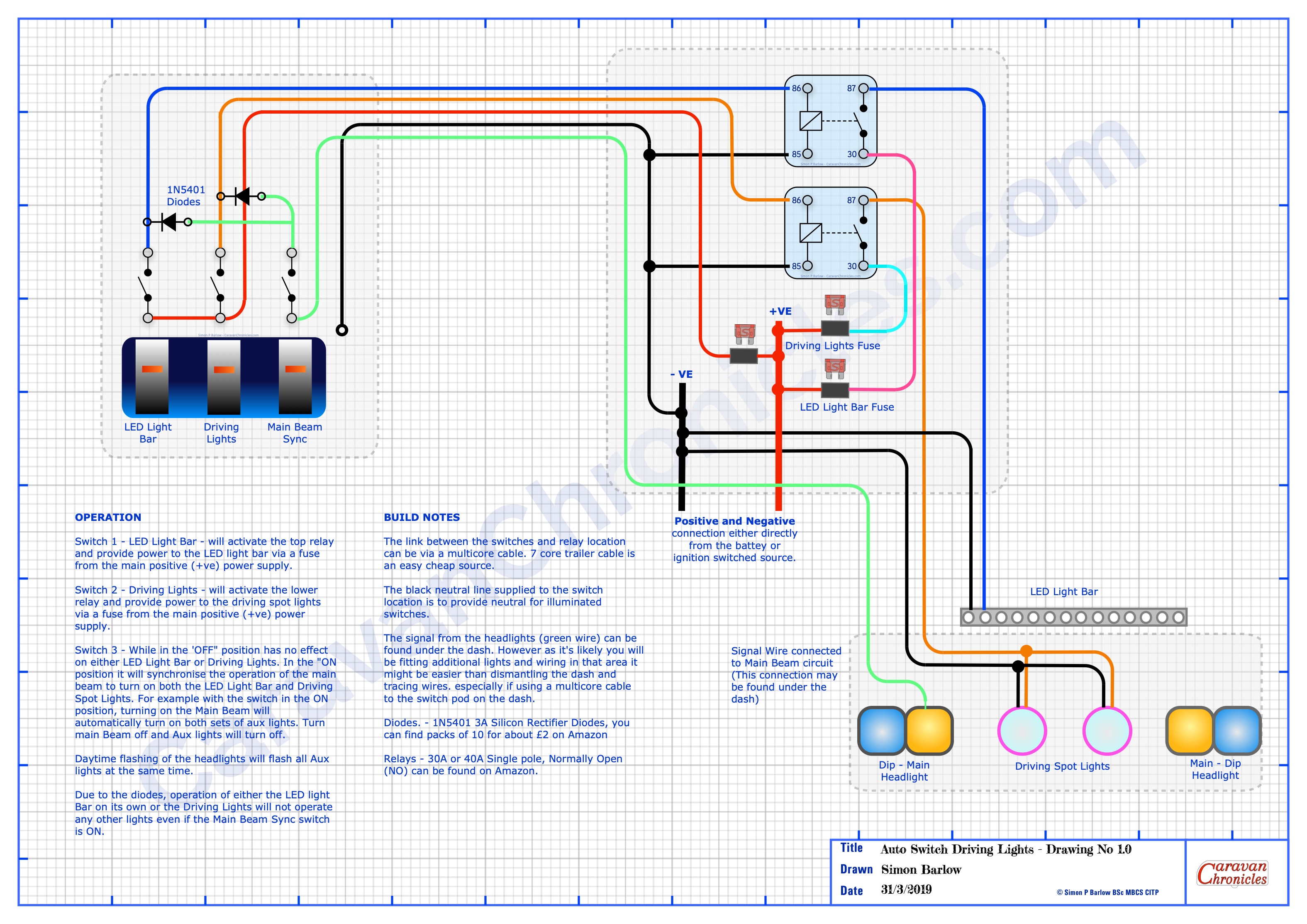
“How can I get my LED light bar and spotlights to come on when I use my main beam switch but I want to disable them when on the highway?”
The questions were from a number of 4 x 4 Off Road enthusiasts and Overland vehicle people. Simplest way I could come up with was using a couple of diodes (details on the drawing) Three switches… one for LED Light Bar, One for Driving Lights and one that allows you to sync the LED Light Bar and Driving Lights to the operation of the main beam in the vehicle. Flash the main beam and with the Sink Switch ON… all the lights will flash. Note… this may be illegal in some countries, so having the option to turn off the facility when on the roads ‘should’ keep you within the law…. don’t quote me on it!!!
Question 2
“Whats the best layout for connecting a solar controller / inverter / isolation switch to my battery bank?”
The best schematic I could come up with that is flexible for most situations. I’ve put a few notes on the drawing. The various components I’ve drawn generically…. all can be found at your preferred supplier.
Question 3
“What’s the basic layout of the vehicle fridge and leisure battery charing circuit?
This I think has come from a few on-line discussions relating to poor performance of the fridge and leisure battery charing in older 4 x 4 vehicles. I was receiving for a while a number of questions related to upgrading older installations. I also receive a number of emails asking how to add the facility of fridge and leisure battery charging to older vehicles and upgrade the 7 pin tow socket or old military lights socket.
You can download the PDF’s and are free to use for personal use. If you post them on other forums I’d appreciate a link back to this page and/or an acknowledgement.
I’d appreciate any feed back in the comments below.
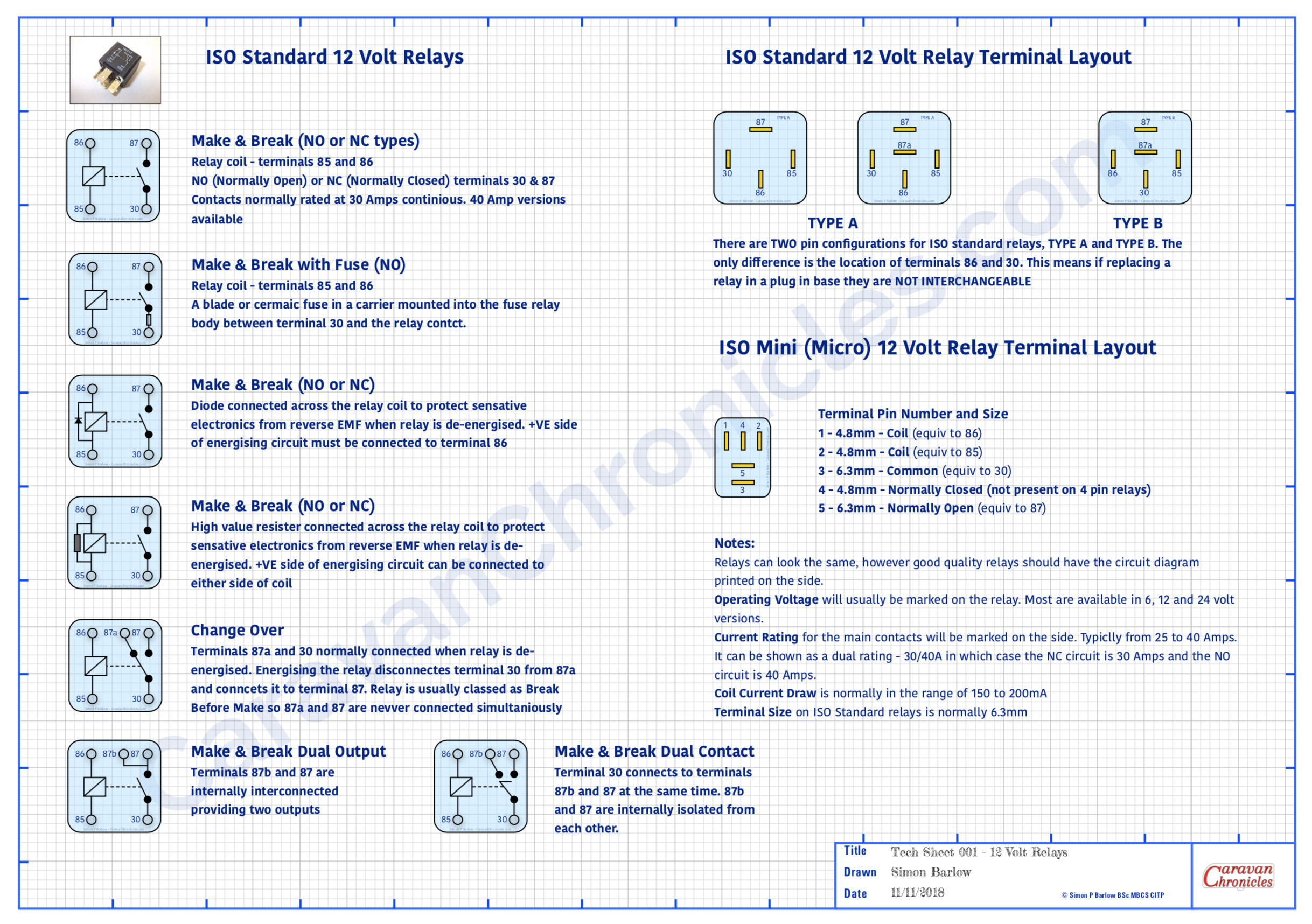
Ok, not one of my usual blog posts. I get a lot of email asking about various electrical items related to caravans and motorhomes and a few things seem to keep cropping up on a regular basis. One is to do with 12 volt relays… what types are there and what are the pin connections.
Another is to do with cable size relating to load and its relation to the length of cable…. “I have a 40 Amp load and its 3 metres from the battery… what size cable do I need?” type questions.
In the past I’ve emailed back with answers, but one caravan engineer asked me if I know of any information sheets that had this type of info that he could put above his workbench.
So I’ve produced a couple of A3 size PDF information sheets (they will print A4) that can be downloaded printed out and pinned up, shoved in your notebook, glued to the lid of your tool box or used to wrap that must have tool present for your beloved caravan or motorhome DIY enthusiast in your life (seasonal eh!)
(I have been told that Office World can print and laminate A3 PDF’s cheaply…. I never knew that!)
I have stylised them as technical drawings and I’ve had to watermark them and some of the icons as I found a lot of my drawings were ending up “as is” or edited on various sites and forums without any credit or link back to Caravan Chronicles. You are free to print out and use them for your own personal use, but if you wish to use them (or any of my drawings) for commercial use, inclusion in blog posts or forums please include a credit line back to CaravanChronicles.com and drop me a line to let me know.
We are just back from Chester Fairoaks after doing the Chester Christmas market and a bit of shopping at Cheshire Oaks Designer Outlet Village and will be adding off to York for a bit more Christmas Market action.
I have a couple of more information ‘posters’ in development but if you have any ideas for future offerings, drop a line in the comments below. Of course my legal advisor – Henry has asked me to point out E & OE
(Everything on the internet is improved by a cat apparently… so here’s Henry)
After a quick four-day break at the Caravan & Motorhome Club’s site at Wirral Country Park (excellent by the way… already trying to work out when we can go back!!) and a bit of work getting in the way it was time to get going again not he catch can… really it should be called the “Air Oil Separator” Install.
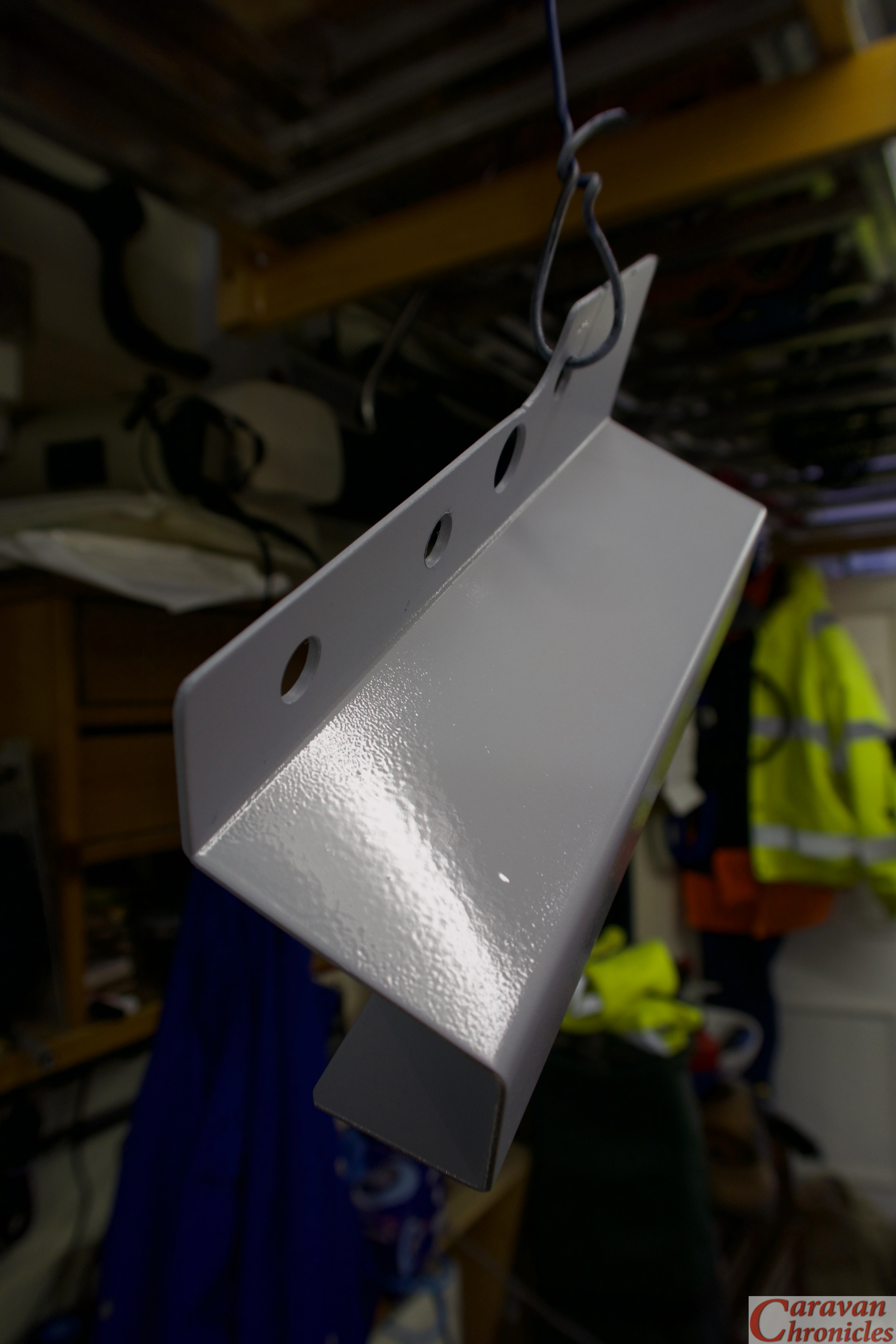
Last time, I’d decided if IKB would have been shaking his head… then it wasn’t right. I decided to make a new bracket out of 1.8mm aluminium sheet and go into full on origami mode. (ps.. after the last post someone emailed me asking what IKB was…. Mr Brunel was not pleased).
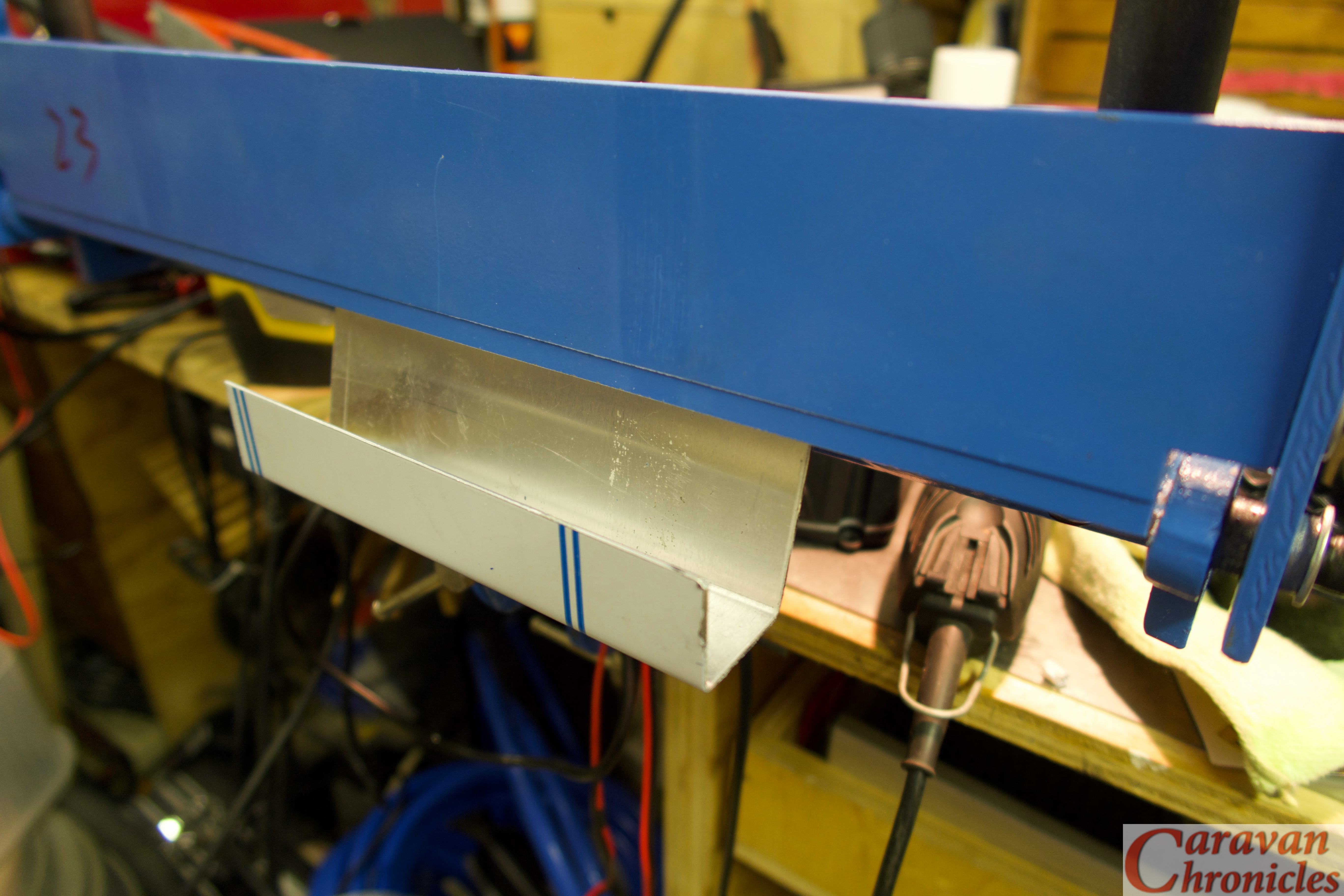
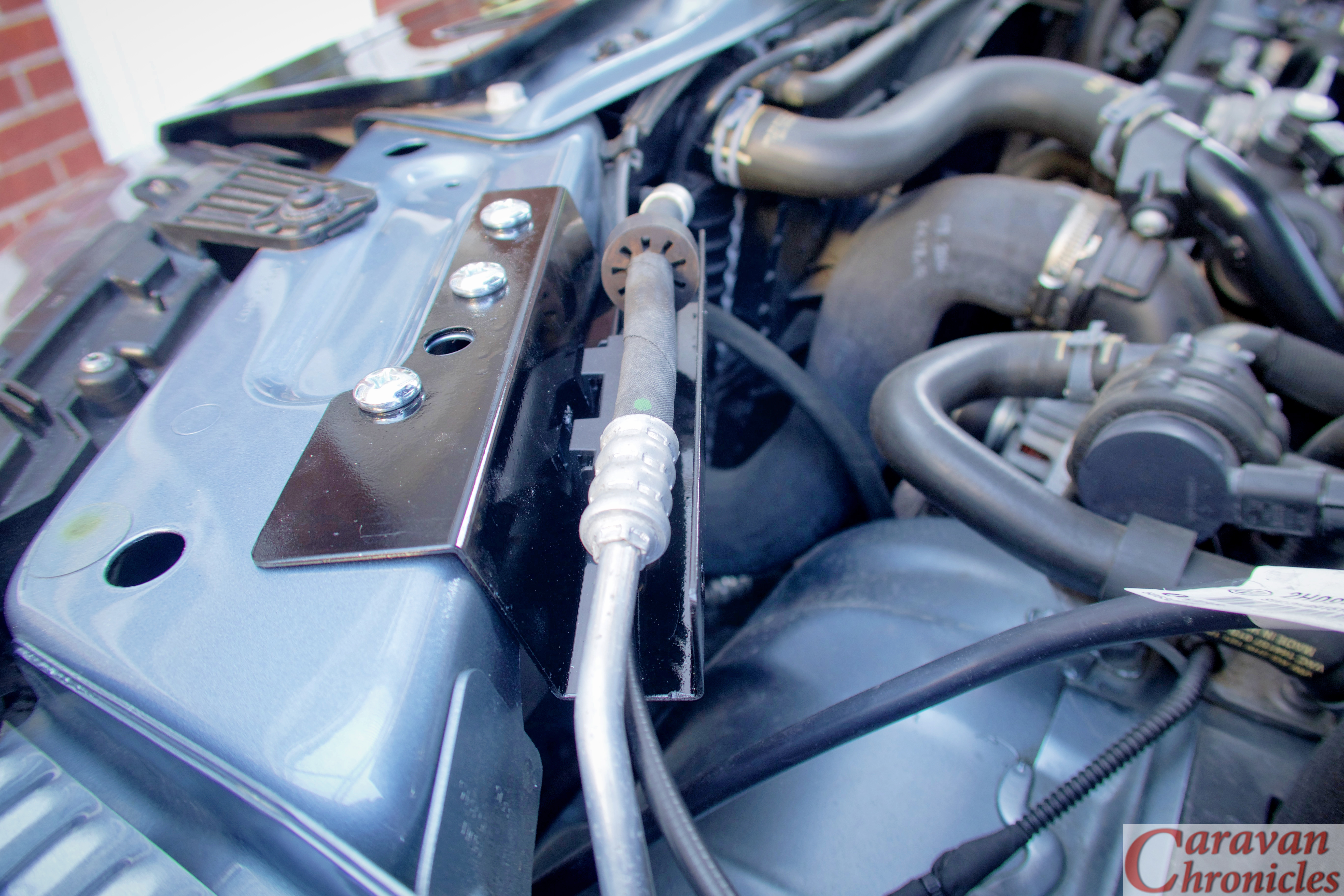
I wanted to make a bracket that passed under the air con pipe and bonnet cable release fitting so that it cleared everything and gave good access at the same time. As a test I did a trial bend if some 1mm thick steel I had just to get the shape…
Once I’d got the angles and size sorted it was time to move on to the aluminium sheet. My press brake… well I call it a press brake, in reality its a cheap basic hand folding machine but it works very well as long as you know its limits and don’t get daft trying to fold big stuff. It was all about the angles…
The first two were easy and I could form the lip with two folds, the second was less than 90 degrees so I just about got away with enough clearance. However folding the return that would lip over the front cross brace which was also less than 90 degrees also meant that I’d have a problem fitting it in the folder.
However, a little lateral thinking and taking the blade off the folding machine, inserting my workpiece and re-installing the blade meant I could fold in the opposite direction (downward)… result!
A quick trim and rounding off the edges gave me a rough folded bracket. A quick file of the edges and work-over with some fine emery removed all the tool marks… quickly followed up with a coat of etch prime to protect it.
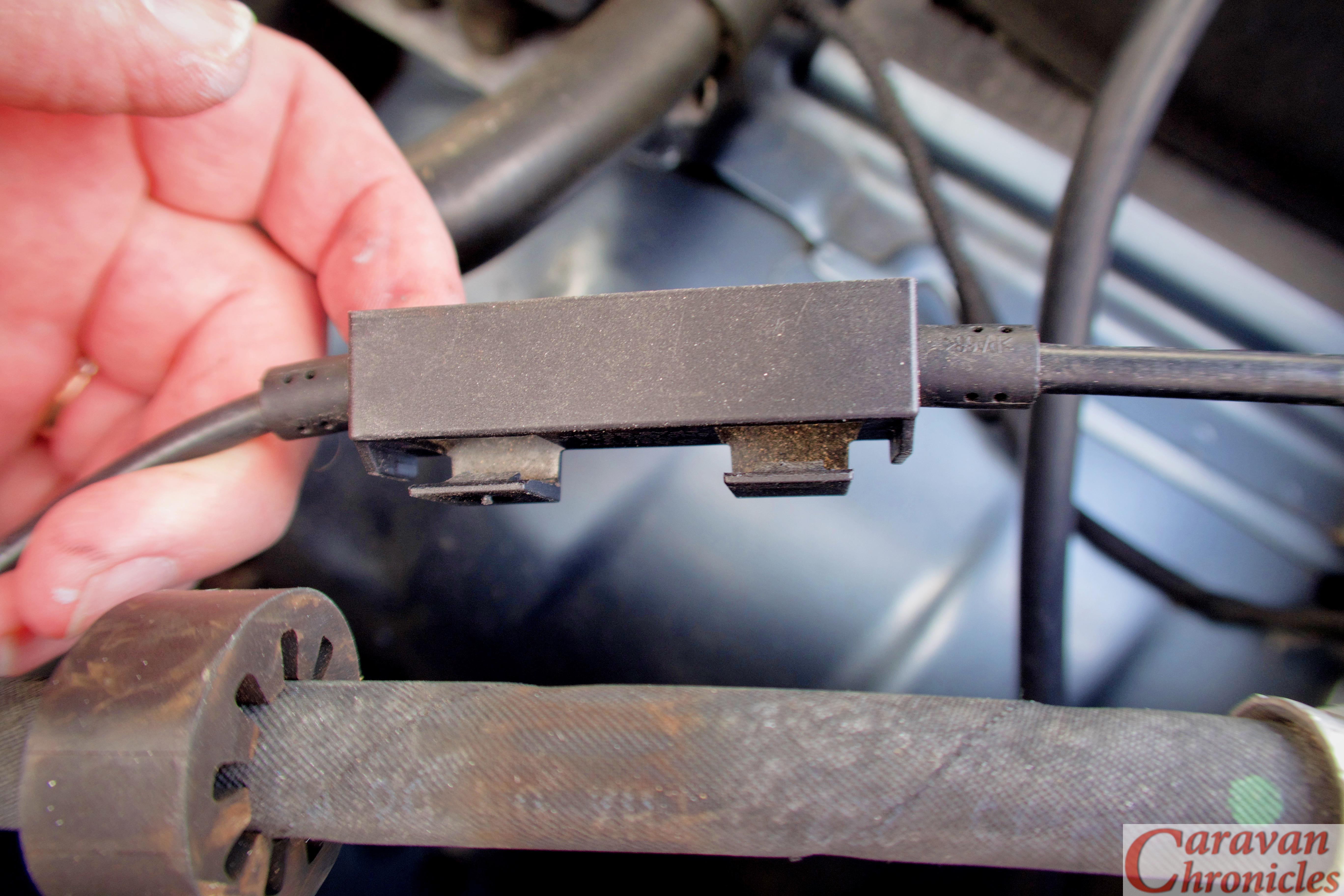
I now had to work out how to mount the plastic housing the bonnet release cables were located in. On the rear of the fitting were two plastic tabs that locked into two square holes punched into the vehicles cross member.
So a few minutes spent with a dremmel and a couple of suitable sized swiss files later…
… and the piece was ready for a final rub over with scotch bright a second coat of etch primer and two coats of black.
The Installation…
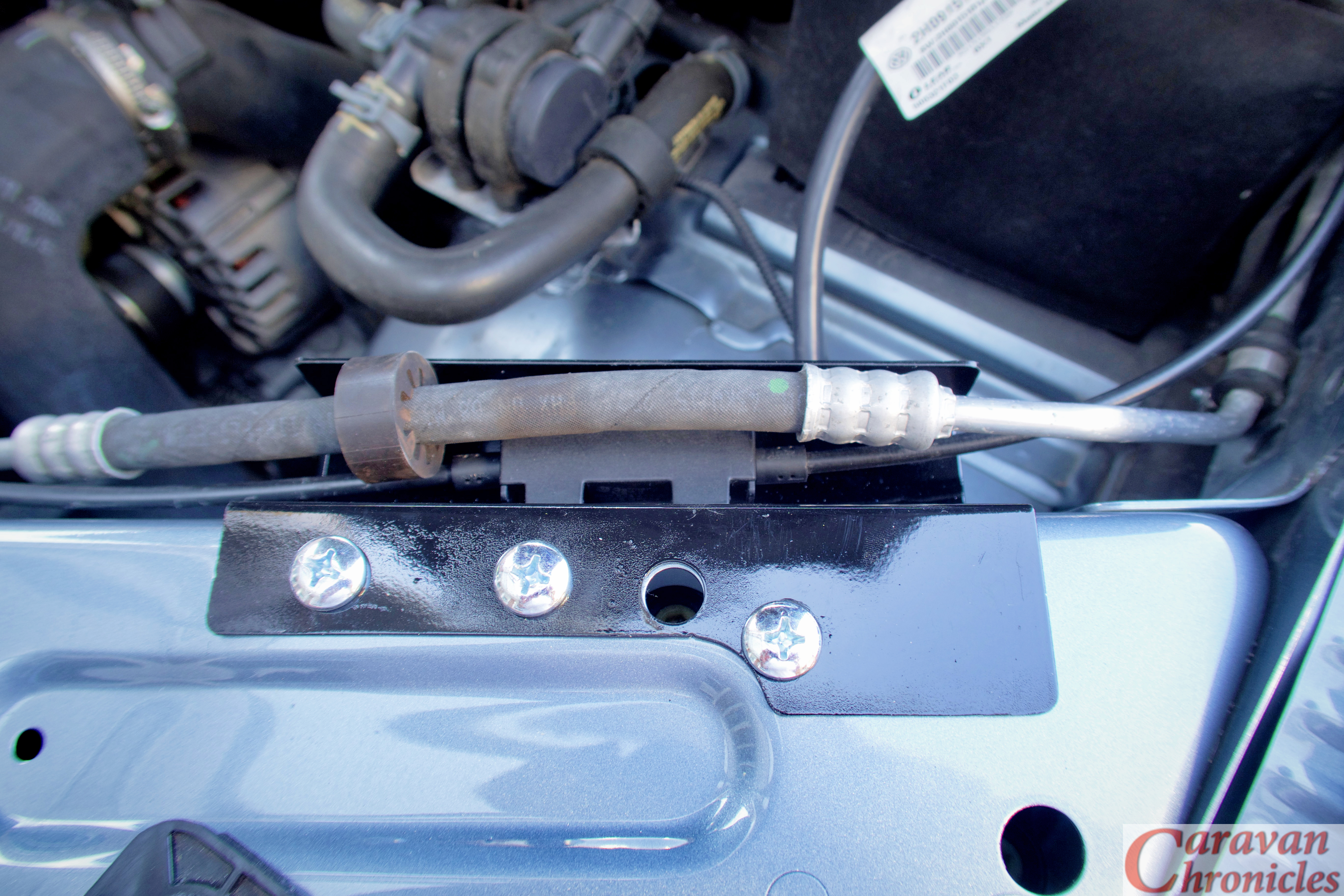
All went a bit easy actually… which is flipping’ unusual for me. I released the bonnet (or ‘hood’ for my American friends) cable fitting and simply clipped it back in to the two new holes I’d made.
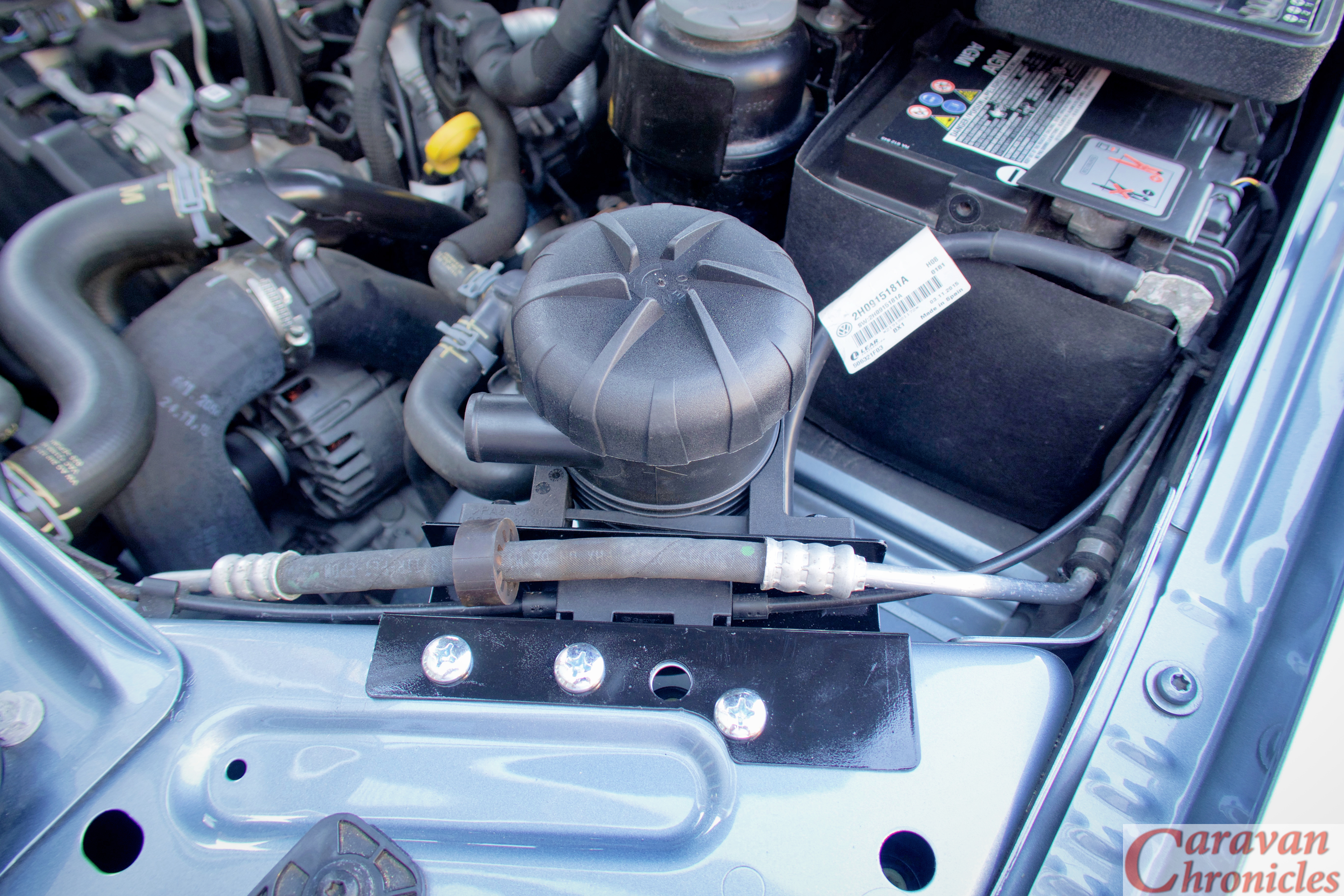
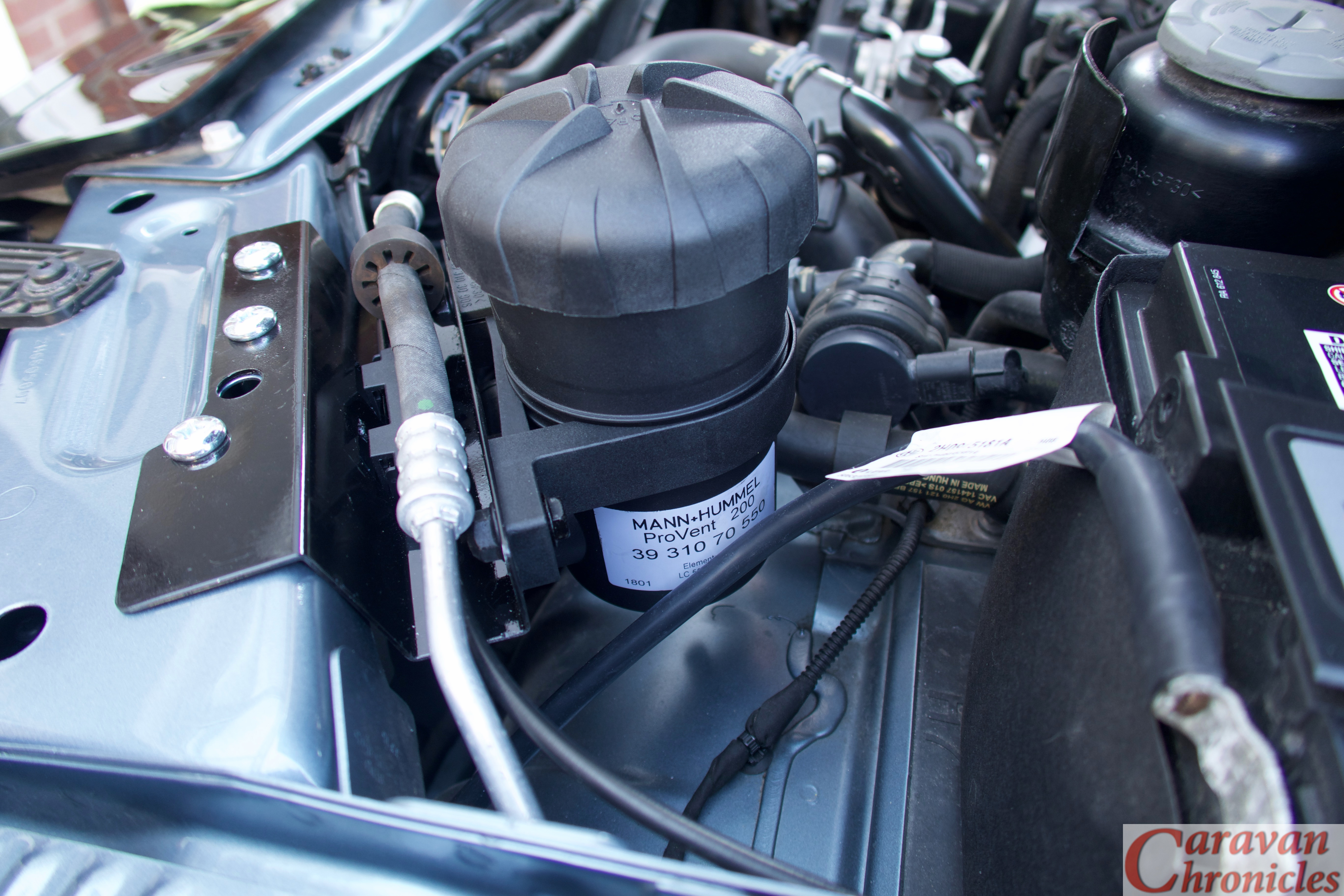
The Provent was installed next…
… again without any issues. Next was to sort out the plumbing.
I’d done a bit of research and asking around and the guys at ASH… AutoSiliconHose.comhad come highly recommended. So a road trip over the Pennines to Mirfield (just east of Brighouse in West Yorkshire) was scheduled.
I had a basic list of what I thought I’d need and the chap behind the counter hooked me up with everything… including the alloy couplers he cut to size while I waited. Great service from ASH and I can definitely recommend them.
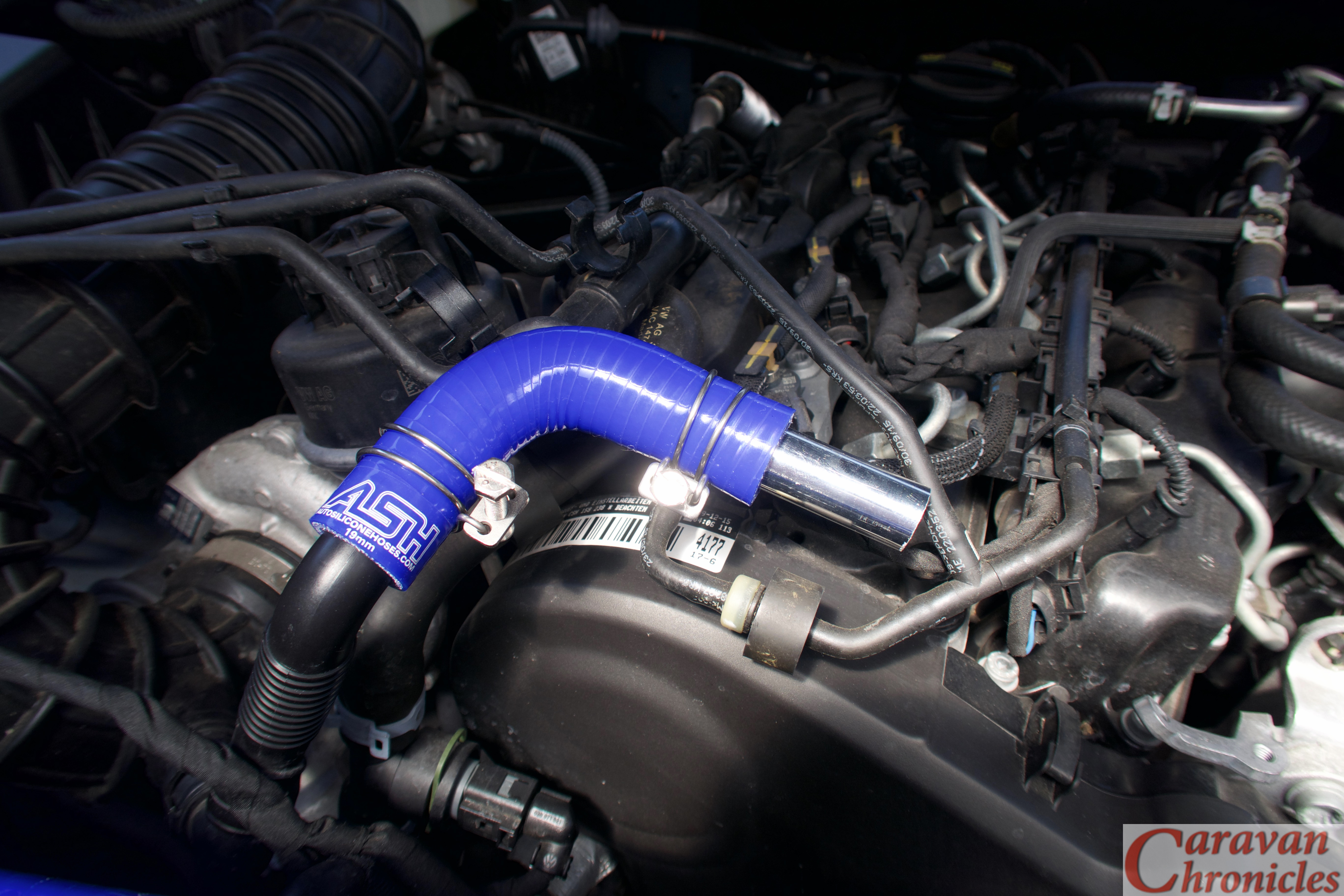
Back home with my shopping, it was time to start on the plumbing.
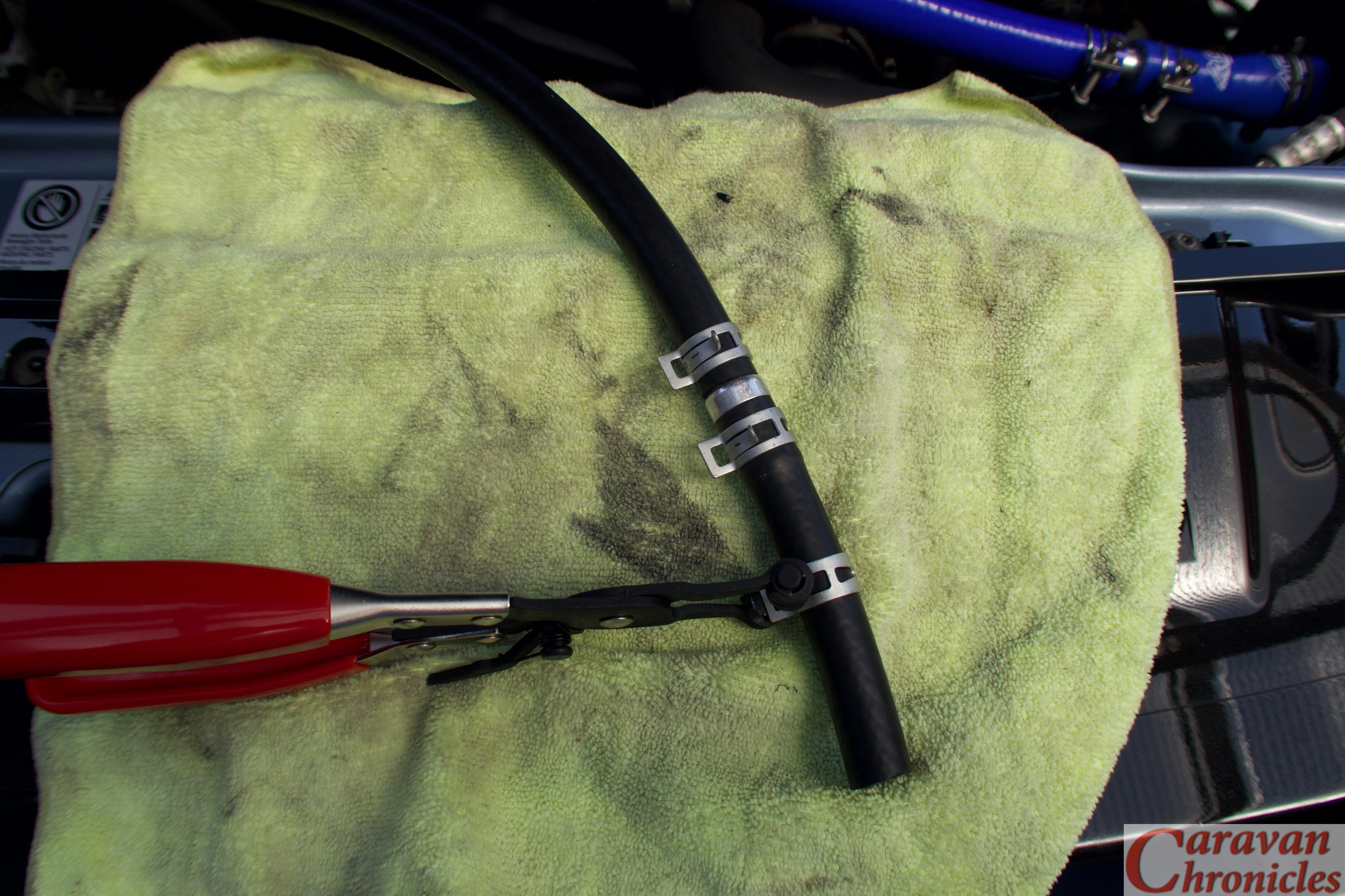
For securing pipes, I personally prefer spring clips… the type you install with special pillars, however the silicon hose OD was slightly too large for may normal stock of clamps so I had to opt for using the wire type. I’ll order some of the correct size and replace the wire clamps as soon as they arrive.
It was really simple now to just assemble the bits, cutting the silicon pipe to length as required. I used a pair of plastic conduit cutters to easily slice through the pipe.
Before I made the final connections to the crank case breather port or the turbo inlet port I blew the pipes clear using a high pressure air line.
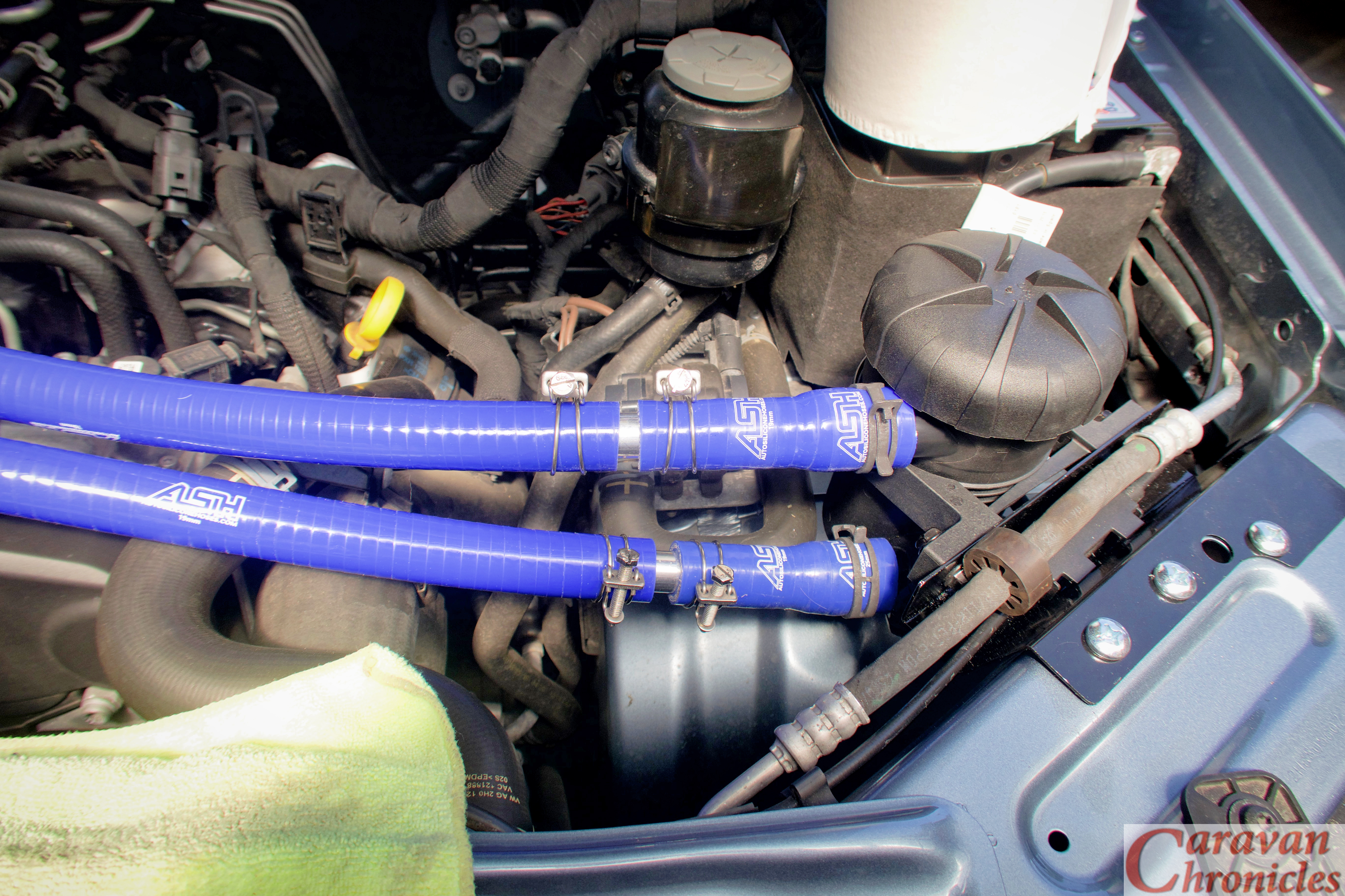
All that was left to do was install the drain hose, one way valve and drain tap. I used normal 20mm oil line for the drain, inserting the one way valve about three inches below the outlet of the Provent catch can. The remainder of the hose was dropped down to chassis level and the drain tap added and secured with a couple of zip ties.
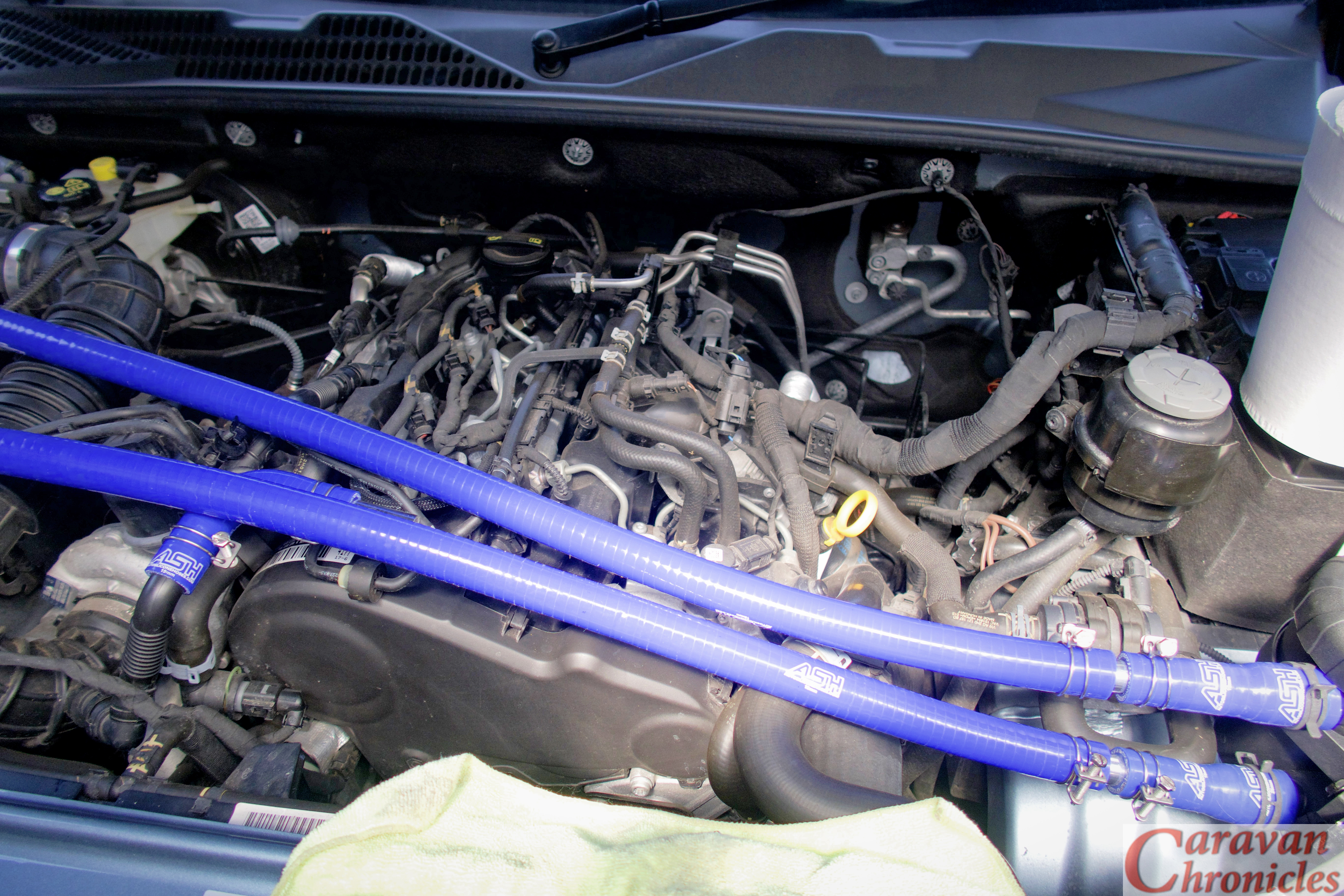
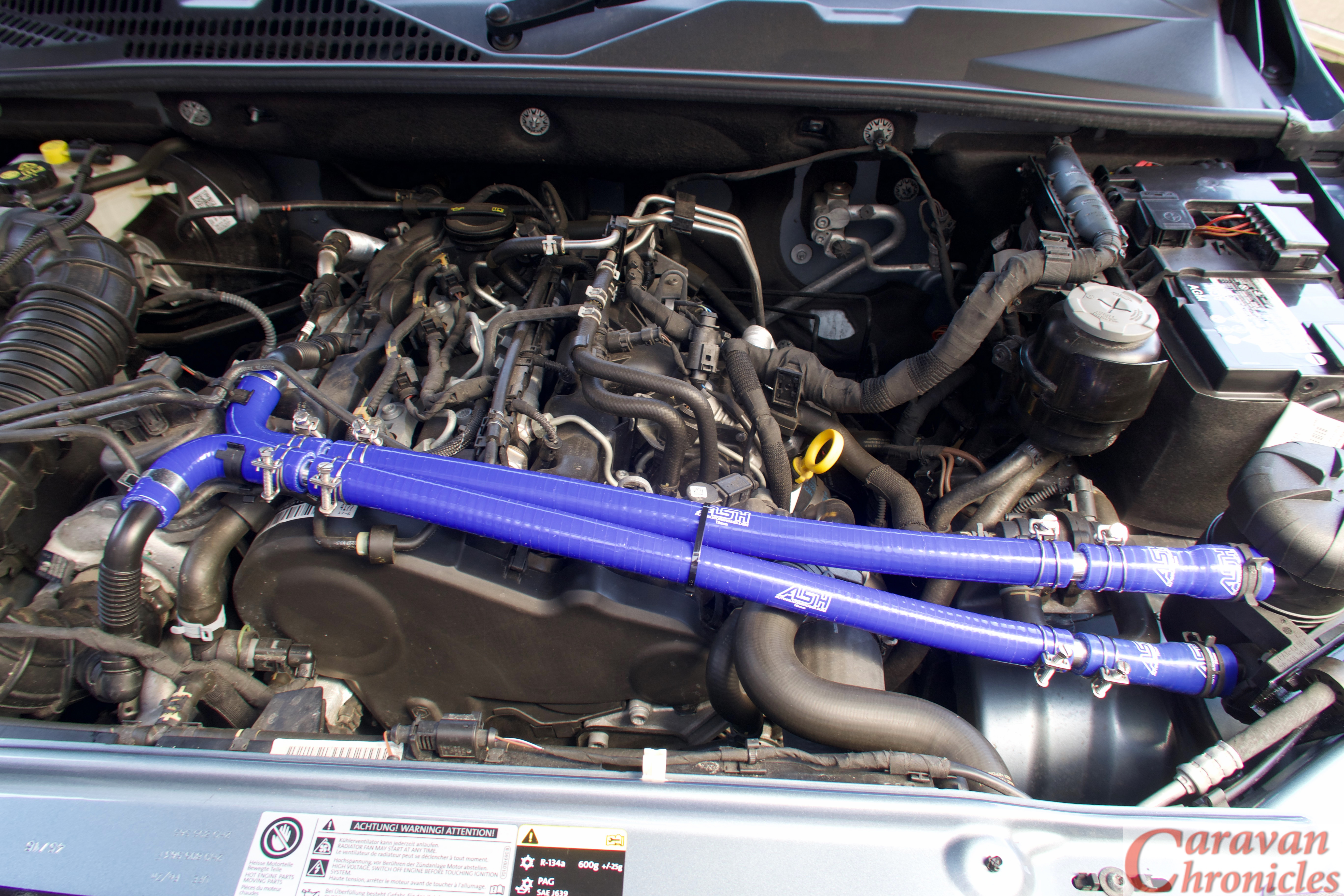
The Finale…
I secured the pipes in a couple of places with zip ties, now I know the route I can make a small stand-off bracket with two rubber lines “P” clips to mount on the engine to hold the pipes, although they are self-supporting because of the short length.
In the photographs above it looks like the piping is tight across the engine, I did do a pull and push test and there is plenty of movement at the 90 degree bends to allow the torque twist of the engine without pulling or pushing on the pipes at the catch can end.
The current mileage is 11,750 or there abouts, so I’ll check the drain and filter in 100 miles and each 100 miles after that so I can get an idea of how the setup is going. I’m not sure how long the filter is designed to last, but Ill put it on the schedule to replace ever main service. The other thing that is an unknown is how much oil I’ll get. I have been watching some YouTube videos made by Berrima Diesel in Australia (if you watch any of the Australian 4 x 4 or off-road channels you will recognise the name). I only found out about their catch can experience when one of the guys from one of the 4 x 4 adventure channels got in touch… even if you don’t think you need a catch can but drive a big diesel their videos are well worth watching.
Ok… I was saying I don’t know how much oil to expect… but it did surprise me that Berrima Diesels posted a video showing a new 4 x 4 with about 6000Km on the clock had produced about 300ml’s of oil using the same Provent catch can. It’s also worth taking look at what the have to say about the current oil specified in diesel engines.
The other thing I noticed was when I left the engine ticking over for about ten minutes. Bearing in mind I had just come back from West Yorkshire via the M62 and M60 and started the pipe install as soon as I got back so the engine was still hot, the difference in temperature between the short length of pipe exiting the crankcase vent and the inlet pipe of the turbo. The pipe exiting the crankcase vent port was almost at the temperature I could not keep my fingers on it, while the inlet pipe I’d connected too was still cool. I’ll have to get my thermomiterbob laser do-hicky out and get some readings… but anything that helps cool gasses going into the turbo has to be of benefit right?
That’s it for now, I know it’s not caravanning related that much… unless you want to get the best out of your diesel while towing. I promise the next one will be caravan related, honest!
As in part one I’d also like to give a shout out to Charles at HumbleMechanic.com for all the information and videos he produces about VW vehicles. Charles has been an absolute gold mine of information for all things VW and if you drive any of VW’s vehicles please be sure to drop in on his YouTube channel and take a look.
Stopping at Rivington Pike services for a coffee. All 38 foot 6 inches of outfit.
Our Freelander is now becoming a grand old lady of 10 years vintage, we have owned her from new and she’s just passed the 90,000 miles mark so we thought it might be time to retire her from towing duty. However we intend keeping her and started to look round for a suitable replacement to take on the task of towing the caravan. As at some point in the future we hope to move up to a twin axle, twin bed caravan I started looking for a vehicle that would be capable of towing what we hope to move towards in the future.
Now, this is my (our) thoughts and the rational for our eventual choice. It may not be perfect for you or even close to perfect, but this is what we considered in our choices and hopefully going through the process will help you now or in the future when you come to start thinking about a new tow vehicle.
There are lots of options and styles and we needed to narrow down the list quite a bit before getting into the detail. I did read all the reviews from the last “Tow Car of The Year Awards” to see what was being considered by the industry as the top performers, but in some respects the awards are slightly tilted in my opinion as they only review vehicles that have been put forward by the various manufacturers…. which I guess is a marketing tool for them. So there are some vehicles that are not in the awards that should be considered.
Types
We have always had 4 x 4’s as our main vehicle, with an eclectic mix of second vehicles, sports cars, saloon cars etc. Personally we don’t think a saloon or estate type vehicle, even a 4 x 4 version would be right for us. This narrowed it down to SUV type 4 x 4’s and 4 x 4 pickups.
We have nearly always had a Land Rover in the family, I passed my test in one back in 1978 and was quite used to them. Sue had been driving one for longer than she will admit to… both Discovery’s and Freelander’s. The only thing neither of us had any experience of owning was a pickup style vehicle.
4 x 4’s – Choosing a body type
So we are now down to SUV’s and Pickup’s. We very seriously looked at what we needed or thought we might need.
Currently we have a roll out Fiamma Awning, but this might change so we thought about what we would do with a wet awning when packing up… not wanting to put it in the caravan. We also thought about our bikes, we don’t take them with us on every trip, but on some occasions that we hadn’t we wished we had. The ability to take them easily on every trip was a requirement. We didn’t want to carry them on the roof though, so a rear mount on the vehicle was a must. Currently they hang off the back of the Freelander’s spare wheel and it didn’t interfere with towing the caravan and was fairly easy to load and unload. The idea of lifting them on and off a roof mount didn’t appeal to me.
We have a few things that live in the caravan – levelling blocks, corner steady blocks etc that I’d like to carry in the vehicle, and the Cadac, sometimes we don’t take it due to lack of space in our current vehicle (I hate carrying things on the back seat).
Ease of loading – it’s an art loading up any tow vehicle packing everything in so it doesn’t rattle or move about and is safe, so a rear load area that is bigger than our Freelander was a must. We actually think we are pretty slick when it comes to loading as everything is in stackable “Really Useful Box Company’ boxes.
We naturally started looking at 4 x 4 SUV type vehicles – it’s what we know most about and again being big users and fans of the Green Oval, started looking at Landy’s. Now here’s the thing, at the Land Rover dealers…. as we got out of the Freelander… my wallet went off on its own ordered a coffee and a Panini, sat down and said “no way dude”. The wallet was right. The cost of purchasing, yearly servicing and maintenance of one of the Green Oval products was giving my wallet cardiac arrhythmia. Although it may have topped the tow awards for years, it wasn’t an option for us cost wise.
OK, so what else was there similar to a Land Rover? I listed on a spreadsheet all the alternatives and proceeded to wade through them over the next couple of months.
What you have to be aware of is we started this process over 12 months ago, so I’m compressing the time scale down quite a bit.
From the spreadsheet I whittled it down to engine size, towing capacity, Gross Train Weight, Hitch weight limits, braked trailer limits, serving costs, purchase price, wheel base and rear axle to tow ball length, width, height, cost of tower and electrics…. you name it, it was included on the spread sheet. Eventually I came out with the top three contenders… well on paper at least.
Automatic or Manual Transmission
The final choice was whether to go manual or automatic for the transmission. As much as I like manual transmission for 4 x 4 off road capabilities, we weren’t going to be doing a lot of green lane off roading and automatic was the obvious sensible choice.
So with my spreadsheet stuffed full of info, boxes ticked, lists of suppliers for racks and odds and ends then next task was to visit dealers to push, pull, prod, open, shut, question and test drive my (our) top choices.
Job done.
A few days later, while driving to work at silly o’clock in the morning (about 4:45 am actually, I do remember it well ) my careful cogitations unravelled in spectacular fashion.
I receive a lot of emails asking where people can buy some of the tools – especially some of the crimp tools and terminations I use in my posts and articles. In the past I have just emailed people back with the details and maybe links. However my last post about cable termination brought on a rather large amount of requests. So I have decided that I will include links to the products on Amazon. So from now on you will see a section at the bottom of any posts called….
Any specific items used will be listed, and by clicking on the link to the item you will be taken to the Amazon store page. If you do decide to purchase anything, it will be from Amazon (or their associates) and delivered by them. It’s just like buying from Amazon directly.
The price you pay is exactly the same as it would be by going directly to Amazon. All I receive is a few pennies from each sale that will help towards keeping the wheels of Caravan Chronicles turning.
I have also created a shopping page that lists the products under a link to the original article. There aren’t any photos, just descriptions to keep the page neat and quick to load. If you want to go back to the article, just click on its title.
I hope you don’t mind me doing this, but it will save you having to email me asking where to get things from and save me a bit of time in replying to everyone.
As it’s now the ‘off season’ for a lot of caravaners and thoughts turn to sorting out those problems that we put up with on the last couple off trips, I thought I’d look at cable terminations. One of the problems that I’m asked about revolves around cable termination in trailer sockets and plugs. Like most things there is a right way and a wrong way of doing it and there is also the compromise.
So what’s the problem?
Well the problem is terminating a cable to a solid metal part. You will most likely see cables that are striped down to the copper conductors and the individual strands twisted together then inserted in a hole with a screw tightened down to hold the conductors. So whats the problem with this? When you tighten the screw it’s turning obviously and the end of the screw twists down on to the strands of cable, often breaking a few off and pushing quite a few out-of-the-way, usually in an average termination about a quarter of the strands are not held under the screw tip. The 2.5mm square cable you thought would reduce volt drop for the battery charging circuit is now reduced to something less and its current carrying capacity is reduced. Is there a solution?
The obvious one would be to solder the ends of the cable to stop this happening and it’s a great solution, but is does have drawbacks. When you solder the end of a flexible cable the point where the solder stops becomes a weak point and is susceptible to vibration and flexing stress and the thin copper strands transition from being flexible to a solid mass. This is why in aviation, marine and military applications soldering is not usually permitted.
The correct way that flexible conductors should be terminated is by crimping on a “boot lace ferrule”. These are simple brass tubes, sometimes nickel-plated that are slid over the untwisted strands of the conductor and crimped tightly. Some ferrules are just small tubes or ‘U’ shaped section machine crimped and some have a plastic insulator to help isolate the conductor when several are installed in close proximity.
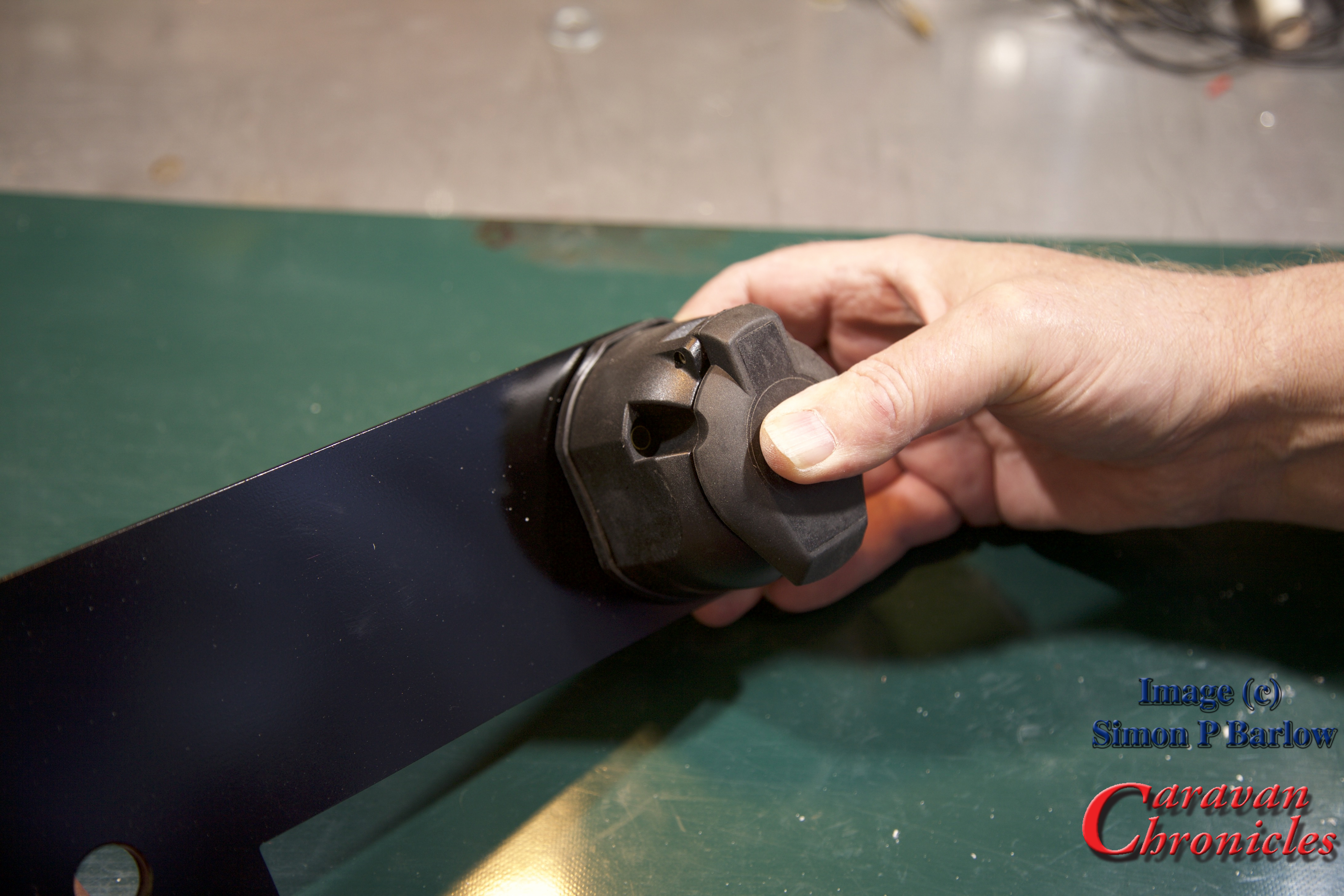
Here’s a simple step by step guide to crimping and terminating a 13 pin trailer socket. It could equally apply to a trailer plug.
For the photos I used a spare socket and short length of standard multi core cable. I have links to all the items, including tools used in the article in “Caravan Chronicles Shopping” at the end.
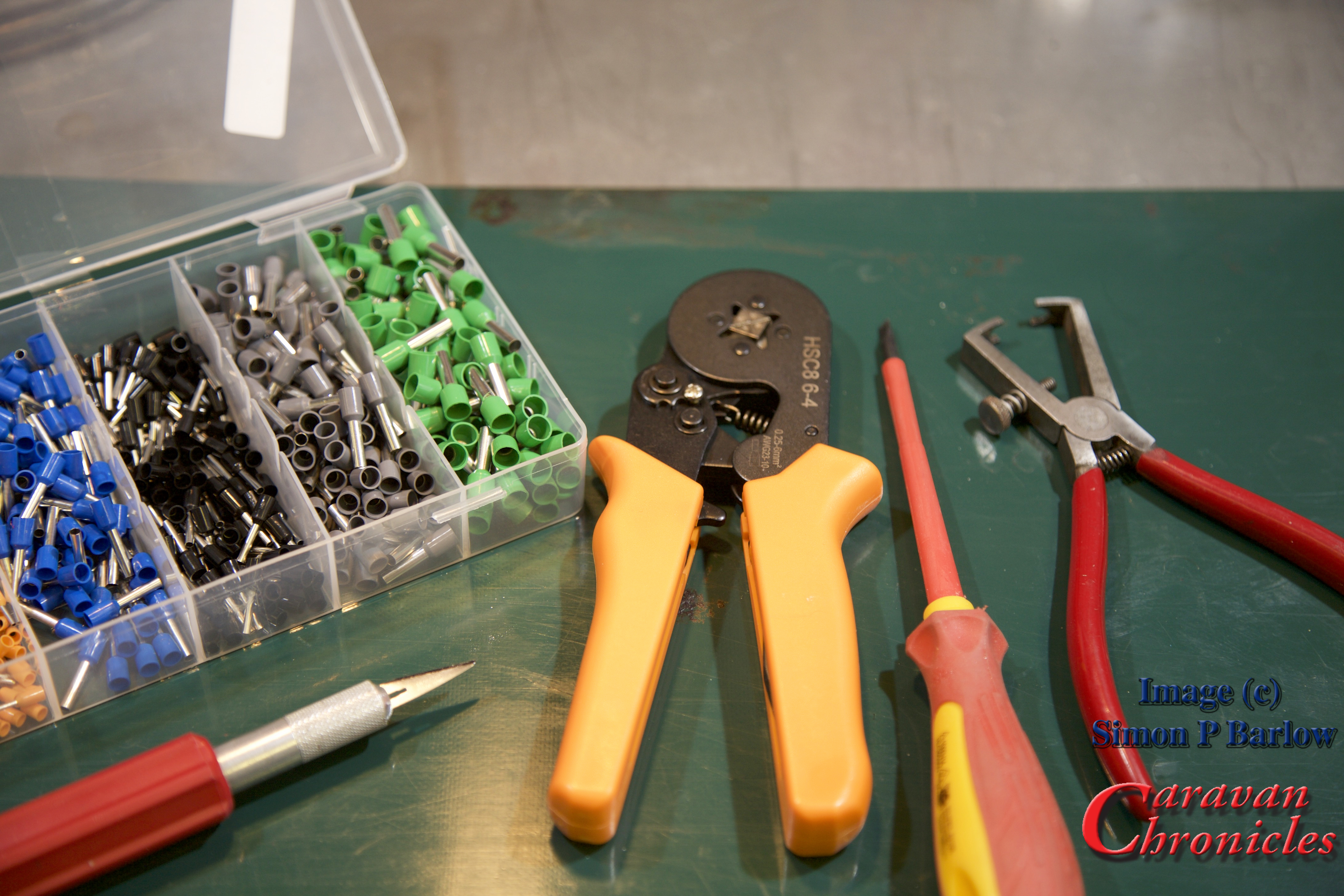
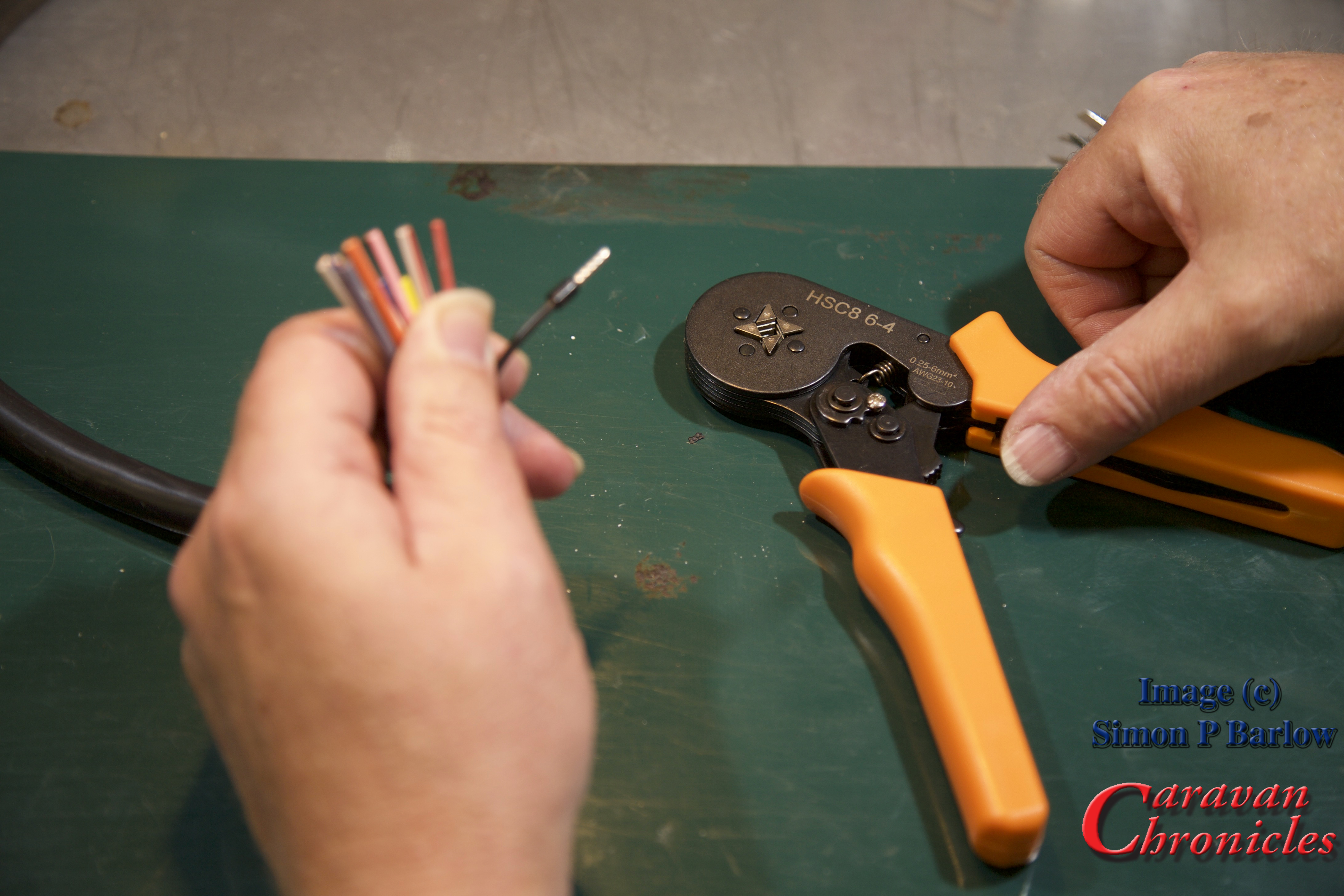
The tools required are a sharp knife, cable strippers, screw driver, ferrule crimps and the ferrules. (tip: make sure your screw driver is a ‘terminal driver’ with flat parallel faces and if fits snugly into the screw head. As the screws are brass, it’s easy to damage the head using the wrong screwdriver)
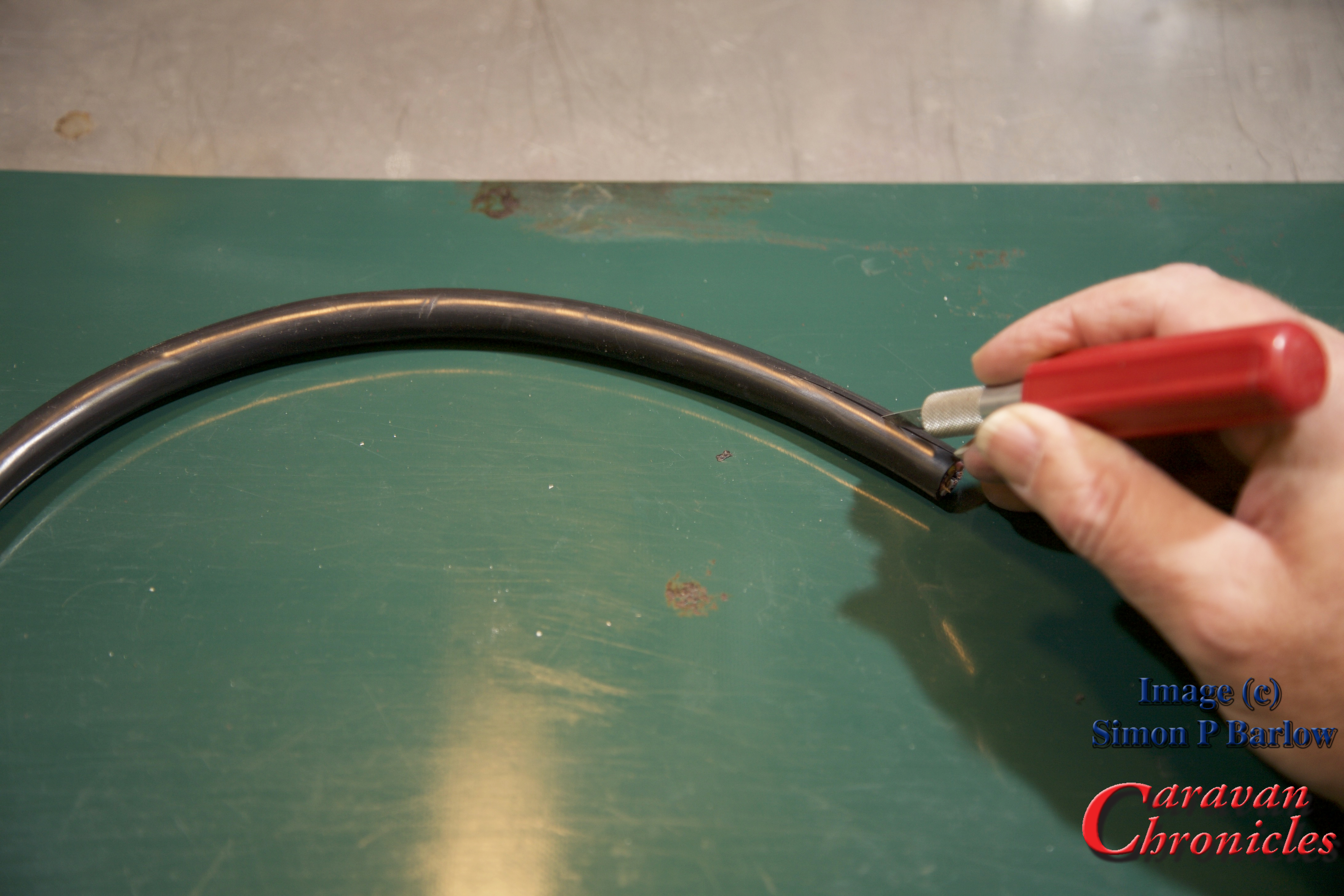
The first step is to trip back the outer cover for the cable. Strip back enough so that the individual cables are long enough to trim to length:
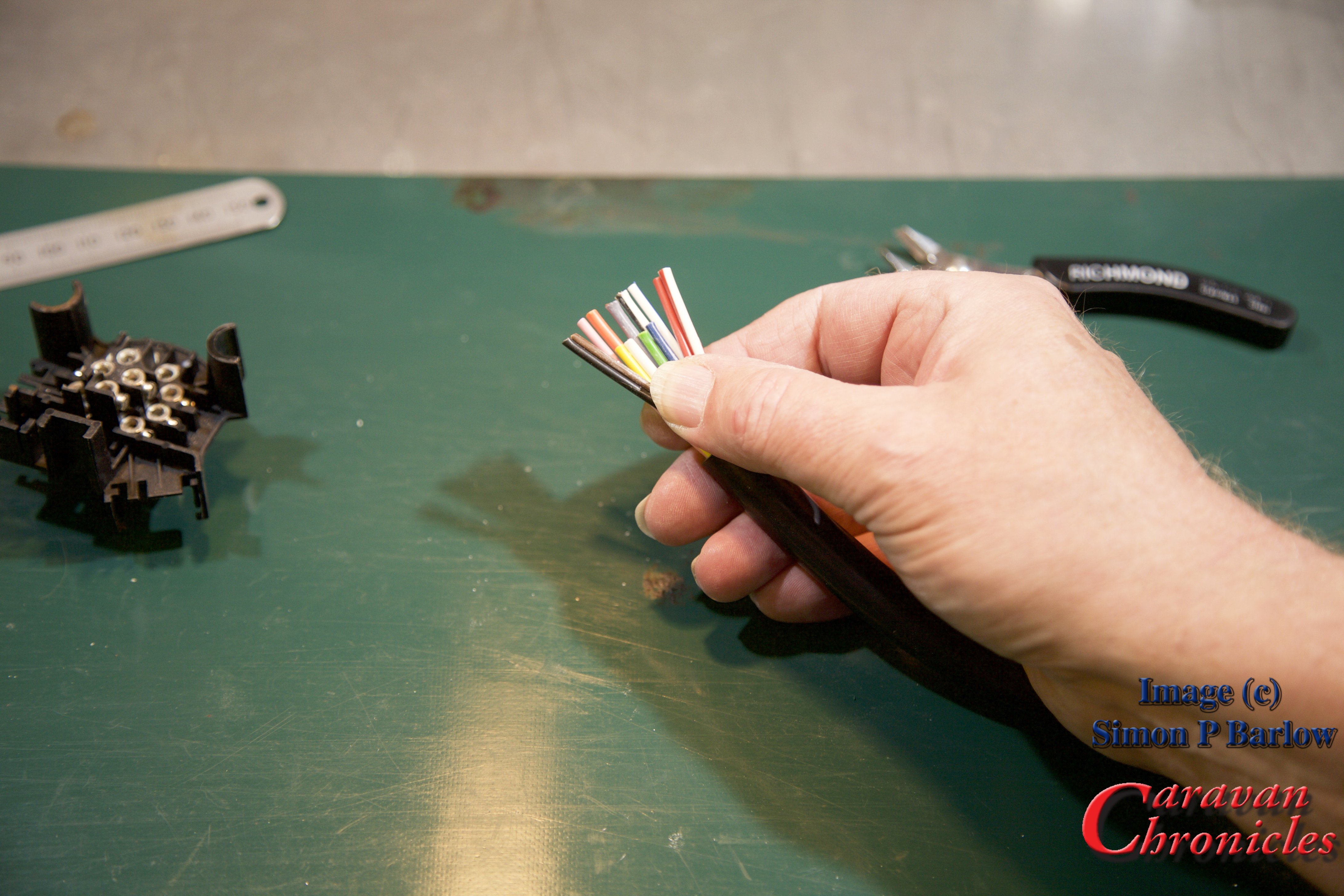
The next thing to check is have you got the right end of the cable? The cable manufacturers lay the individual conductors in a specific pattern so that when stripped, the pattern of colours is in the right order for the end you are terminating. If you have the incorrect end of the cable you will have to cross all the colours over each other to install them correctly in the plug (or socket) As you can see, this is the wrong end for a socket:
Ok, I’ve stripped the other end and you can see the colours are in the right ‘order’ for terminating a socket:
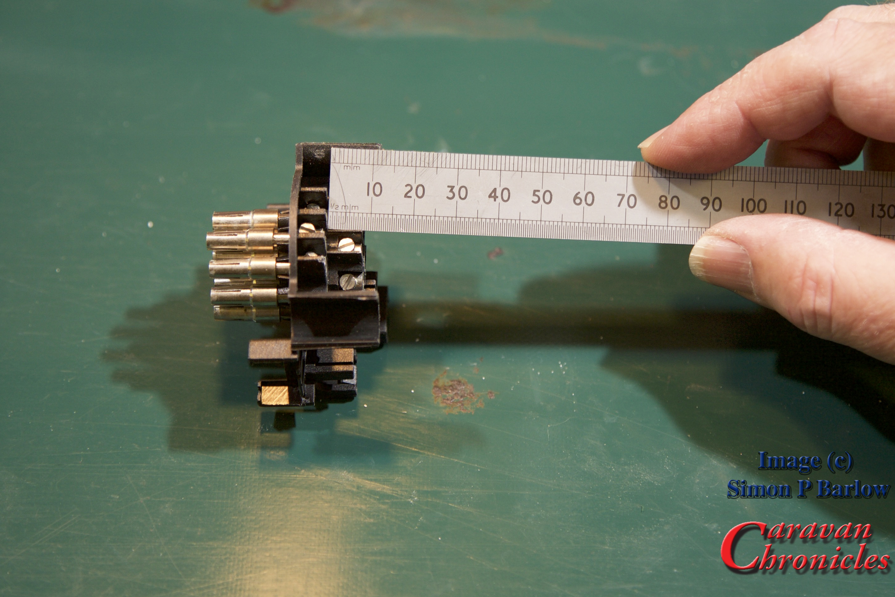
Next we need to measure the difference in termination length between the four centre line and the 9 outer pins… here it’s about 8 mm:
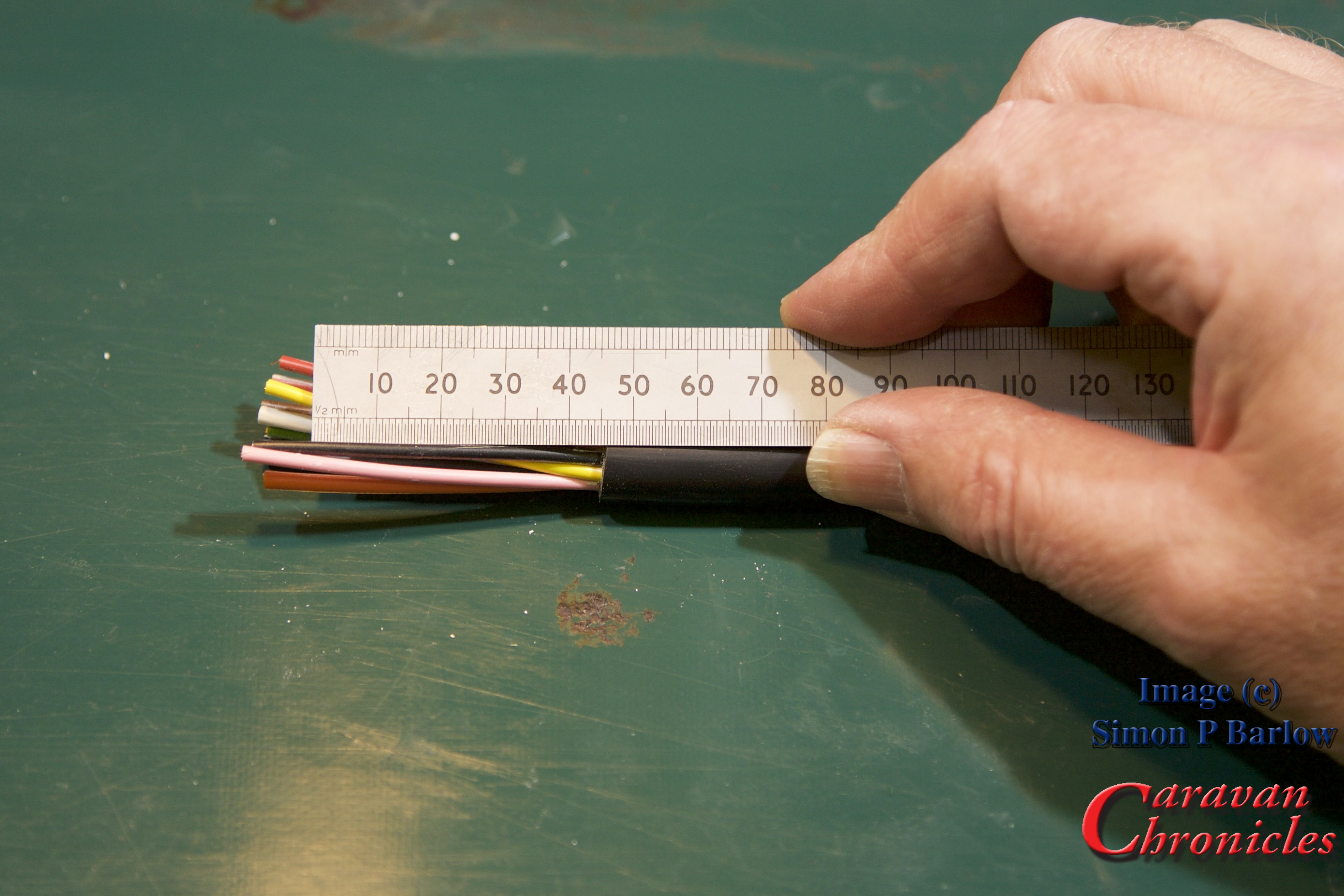
Measuring the back waterproofing cover I know the outer jacket needs to be a maximum of 45 mm from the 9 outer pins and the 4 inner pins need to be trimmed back to 37mm:
Now the cable is cut to the right length so there should be no short or long cables causing problems when assembling the socket:
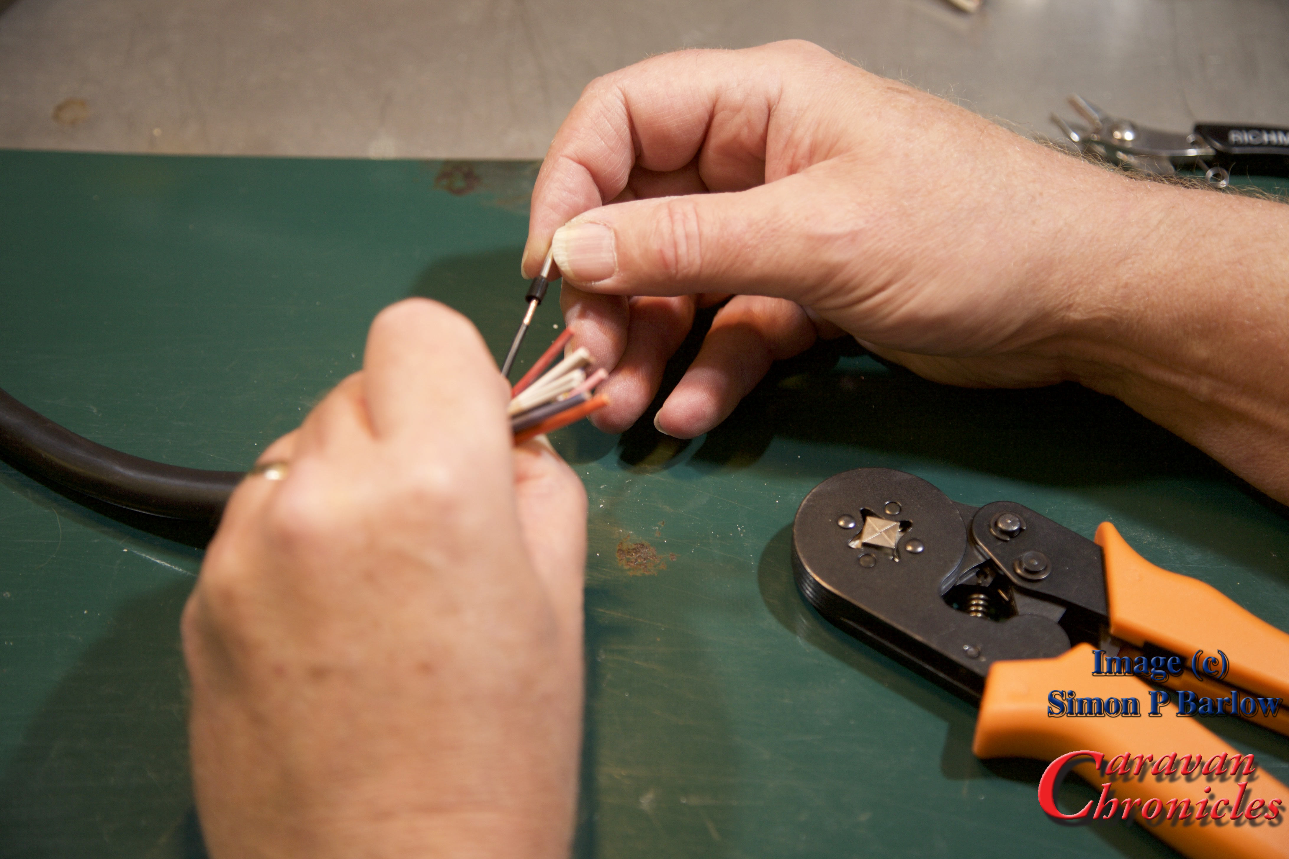
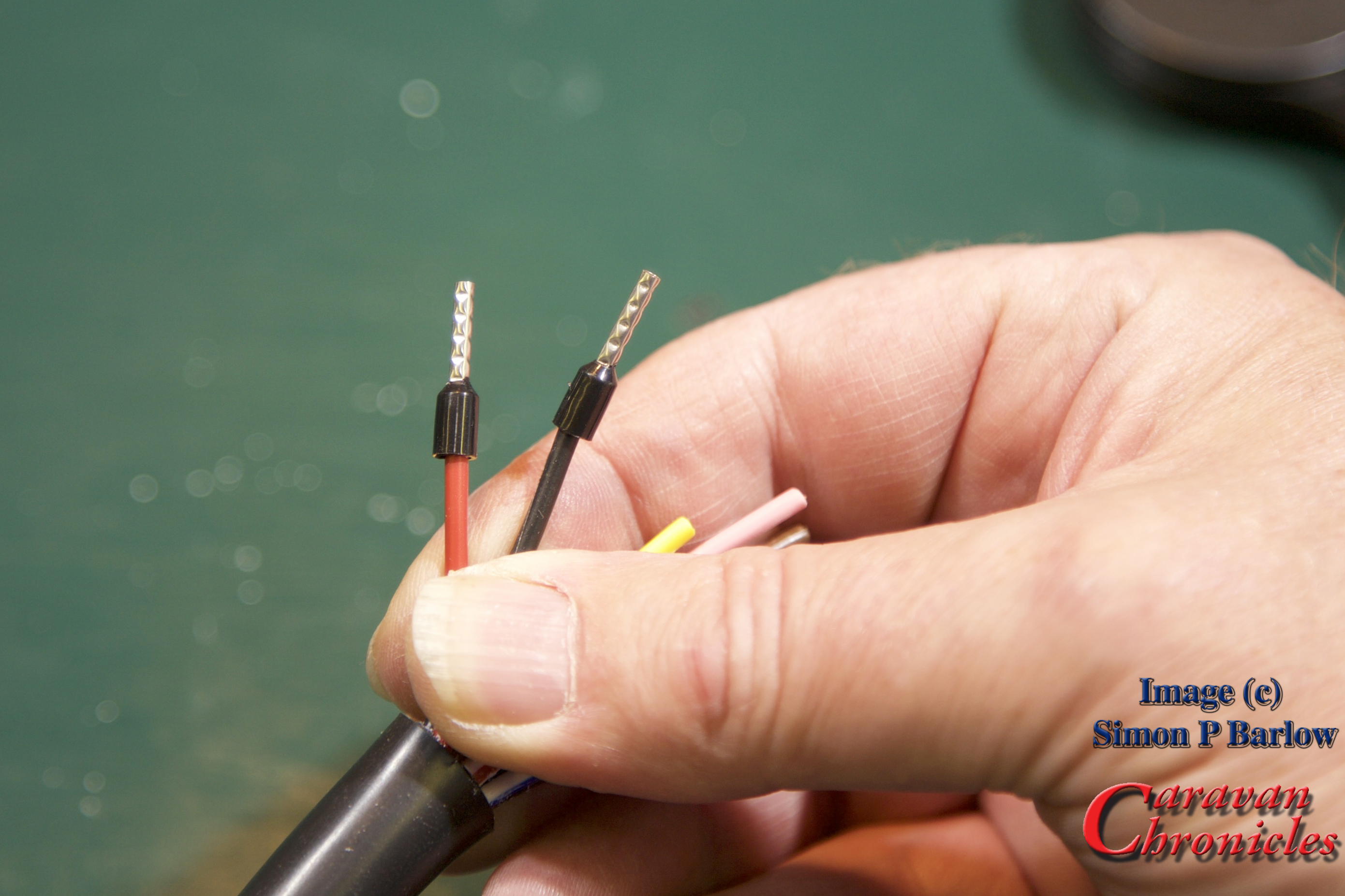
Strip back the individual cables so the exposed conductors are the same length as the ferrules:
Slide the correct diameter ferrule on to the exposed conductors:
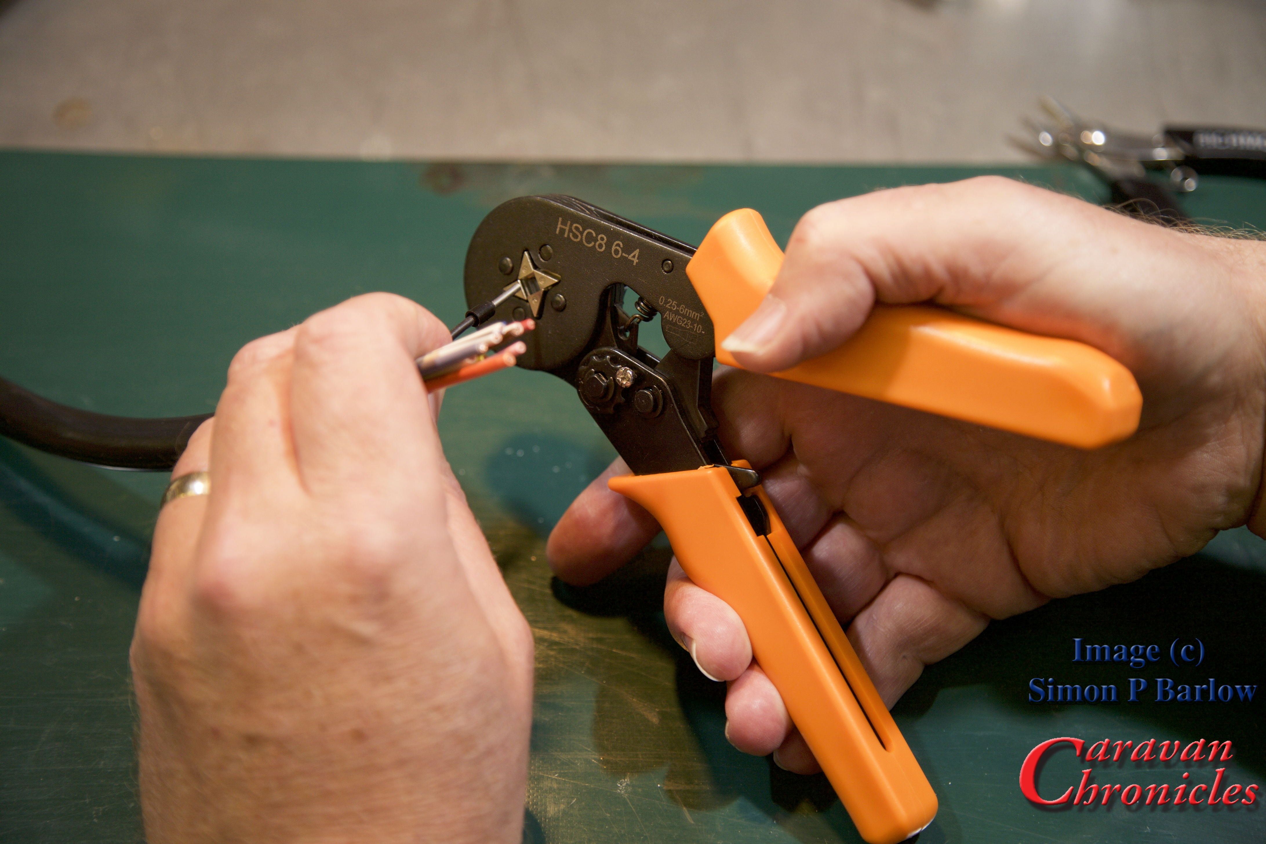
Crimp into place:
The crimp tool is set so that it will only apply the correct pressure to compress the exposed conductors the required amount. Squeeze the handles and the four jaws close on the ferrule and compress it, continue squeezing and once the jaws have attained the right pressure the ratchet mechanism in the handle releases.
If you look at the picture below you will also see that the crimp tool also presses several ridges into the tube, this is to increase the mechanical grip on the conductors and help stop the tube distorting under the pressure of the terminal screw tip:
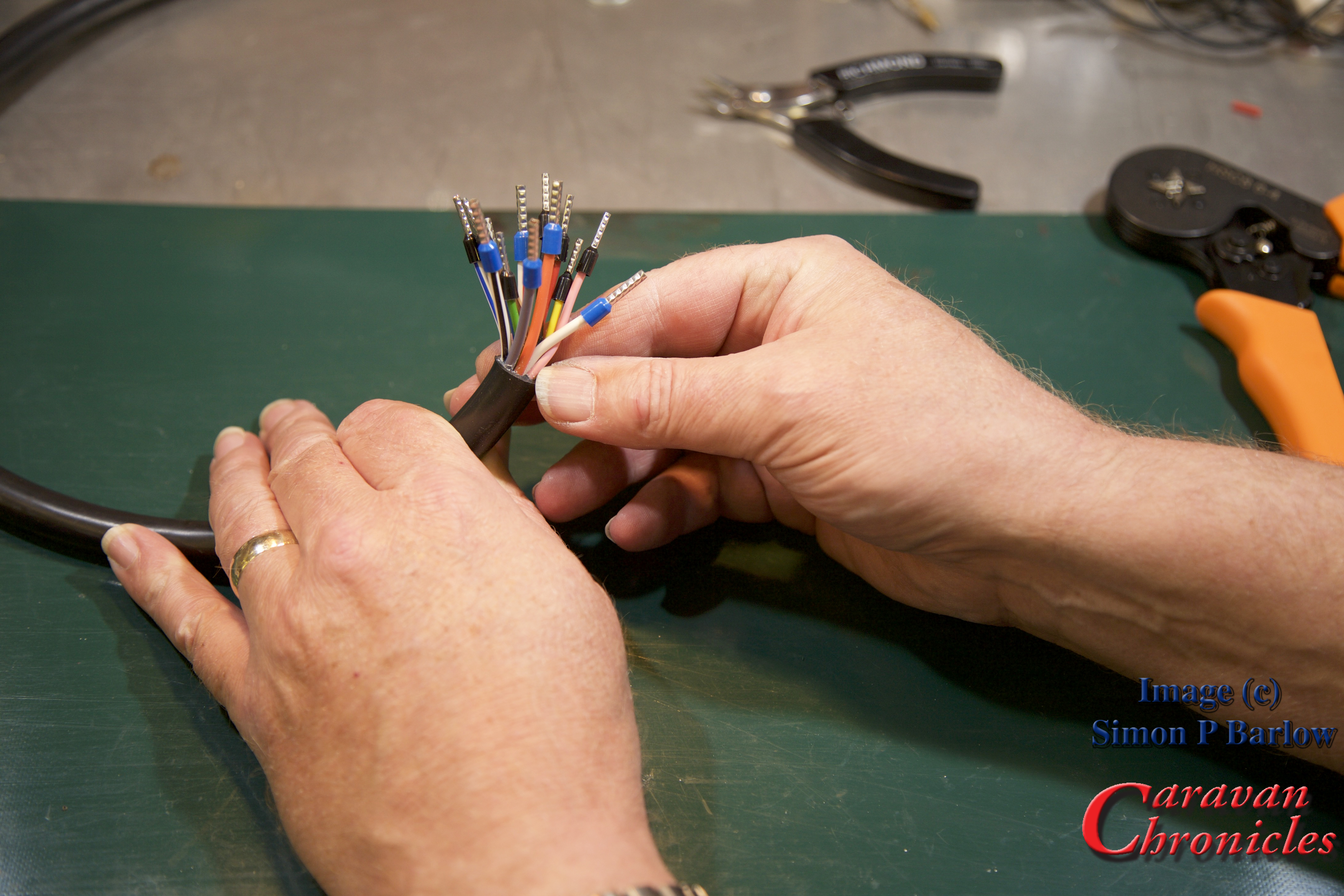
Continue until you have all the cables completed:
One last check… look for stray strands and anything that doesn’t look as though its crimped correctly… give them the ‘tug’ test if in doubt.
I always like to back off the screws so the ends are just visible in the holes:
The next thing you might need to do is correct the length of the ferrule. I have used standard length ferrules and as the holes in the socket terminals are not as deep, I had to trim off the excess. The ridges pressed into the ferrule body help gauge how much to trim off. In this case I only had to snip off to the first indent:
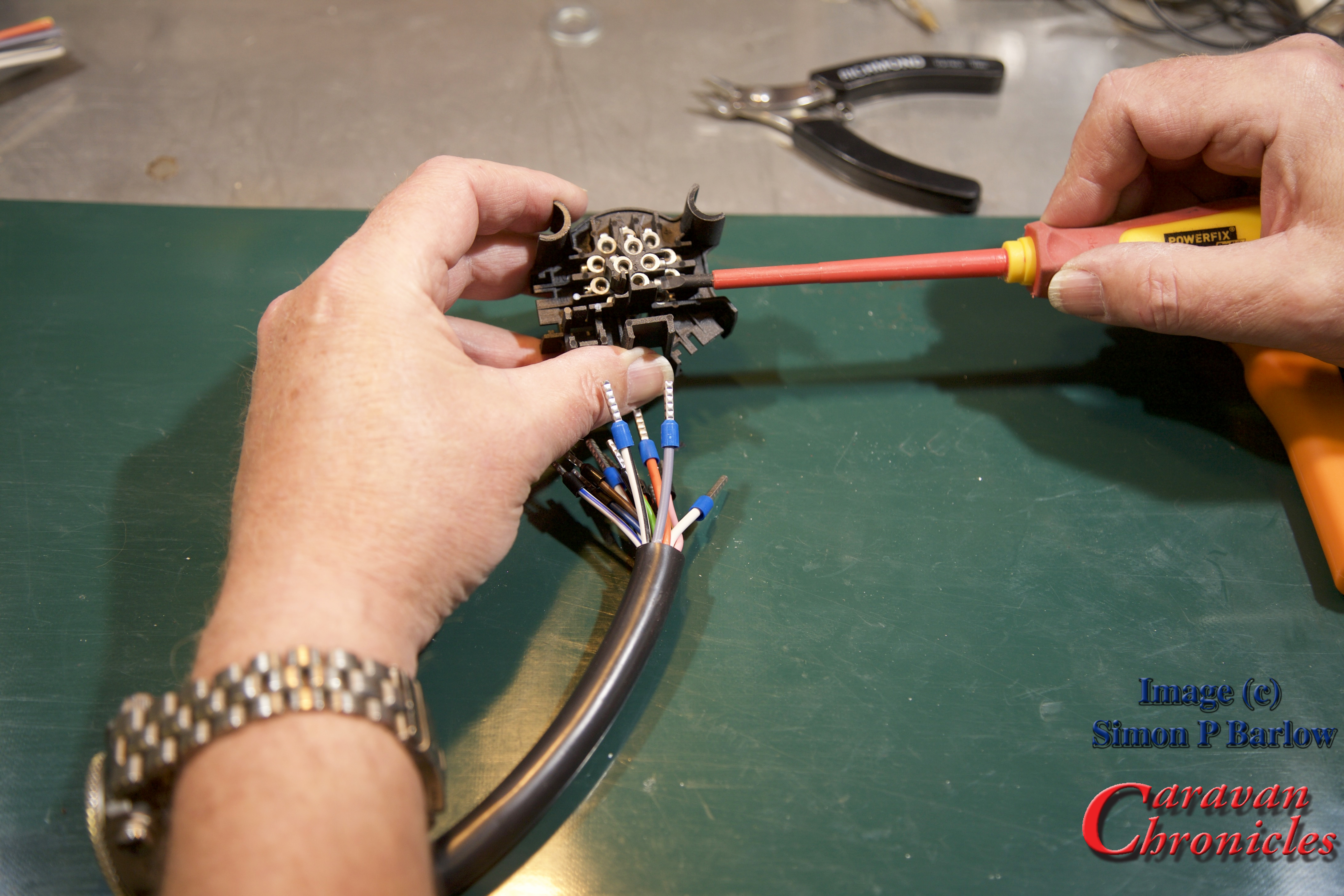
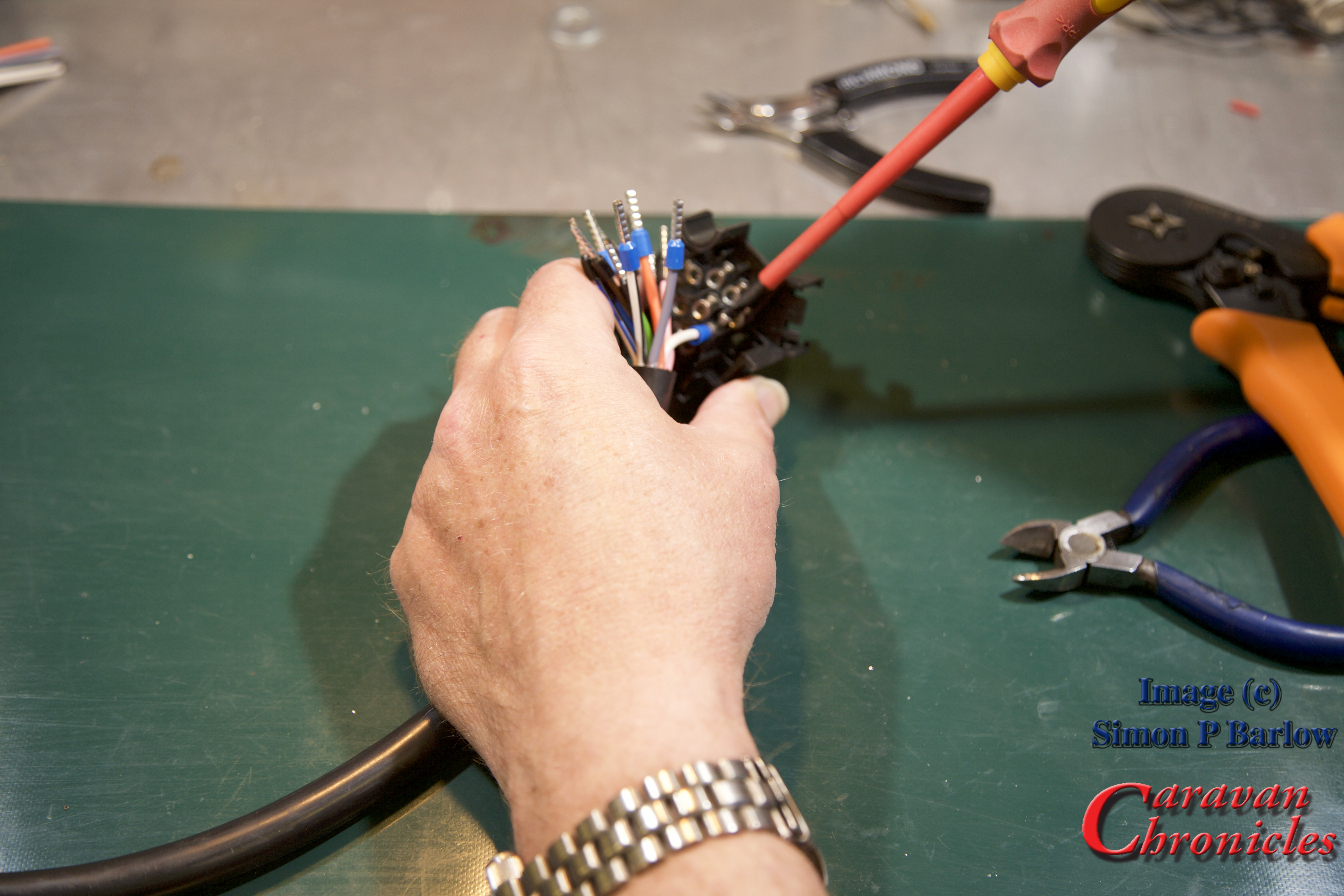
Once trimmed to length, it’s a simple matter of following the colour coding and inserting each cable and tightening the screw. I always start with the four pins in the middle:
Once all the cables are terminated, have a good look to see if all the screws are tight, and of course check the colours are in the right place!
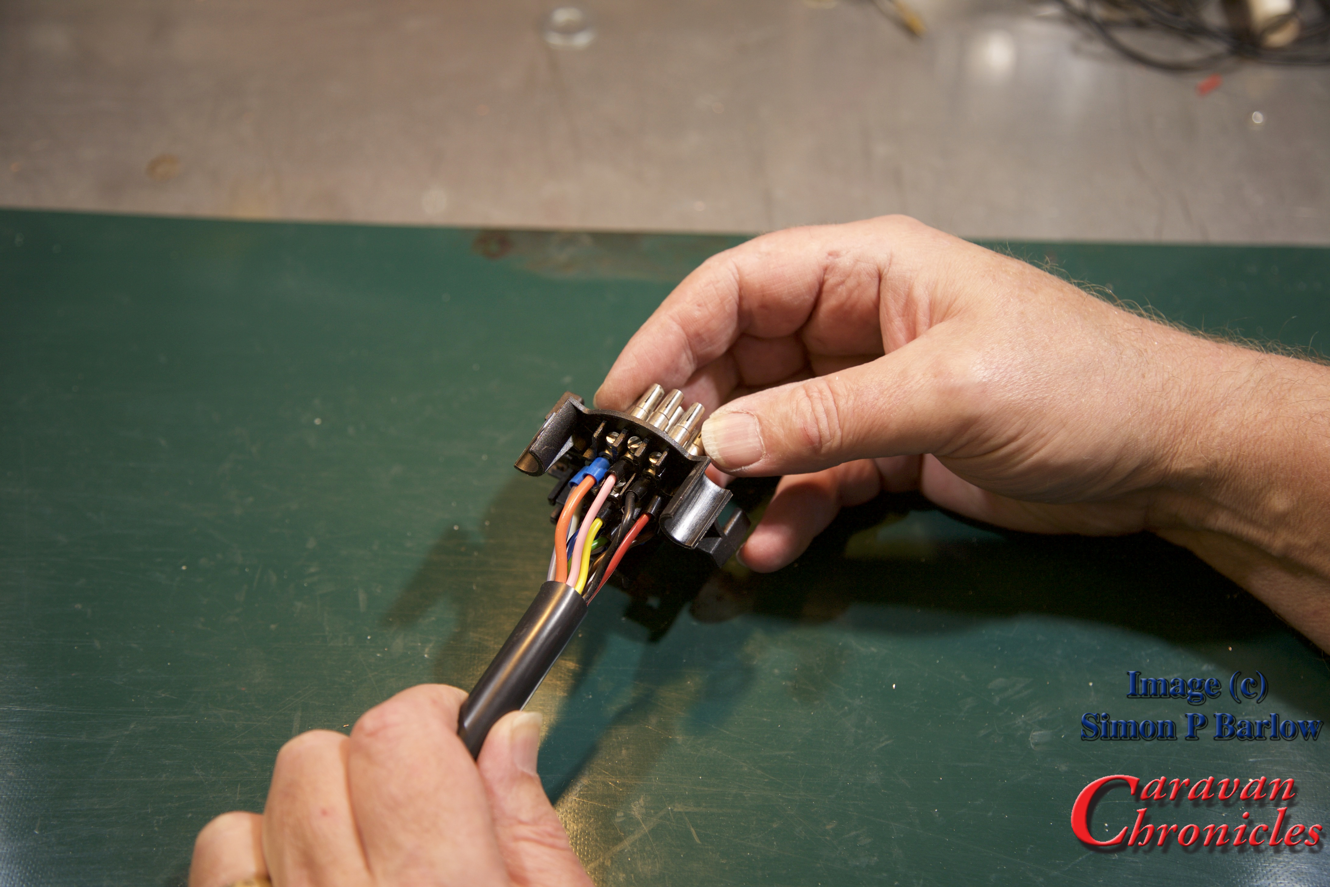
Because the cable was trimmed to the right length before we started there are no loops, so the cover can slide on neatly:
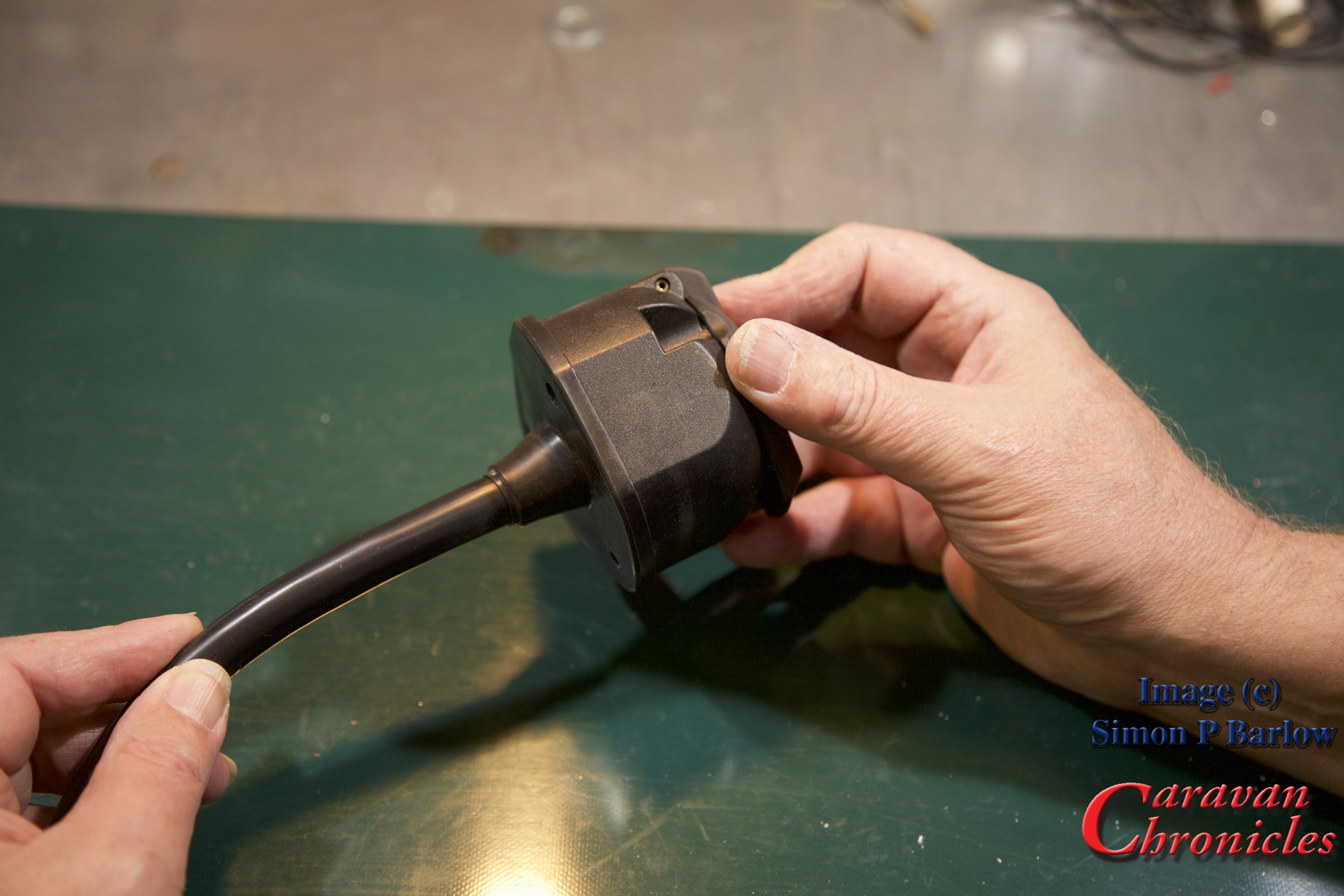
There we go, a finished socket all ready to mount onto the bracket:
To terminate the socket from start to finish and while Sue (thanks `Sue) took all the photos took no more than 25 minutes. Ok it was on a bench and doing outside at the back of a vehicle will take a bit longer, but it’s not that difficult to get a professional result.
The ‘Compromise’
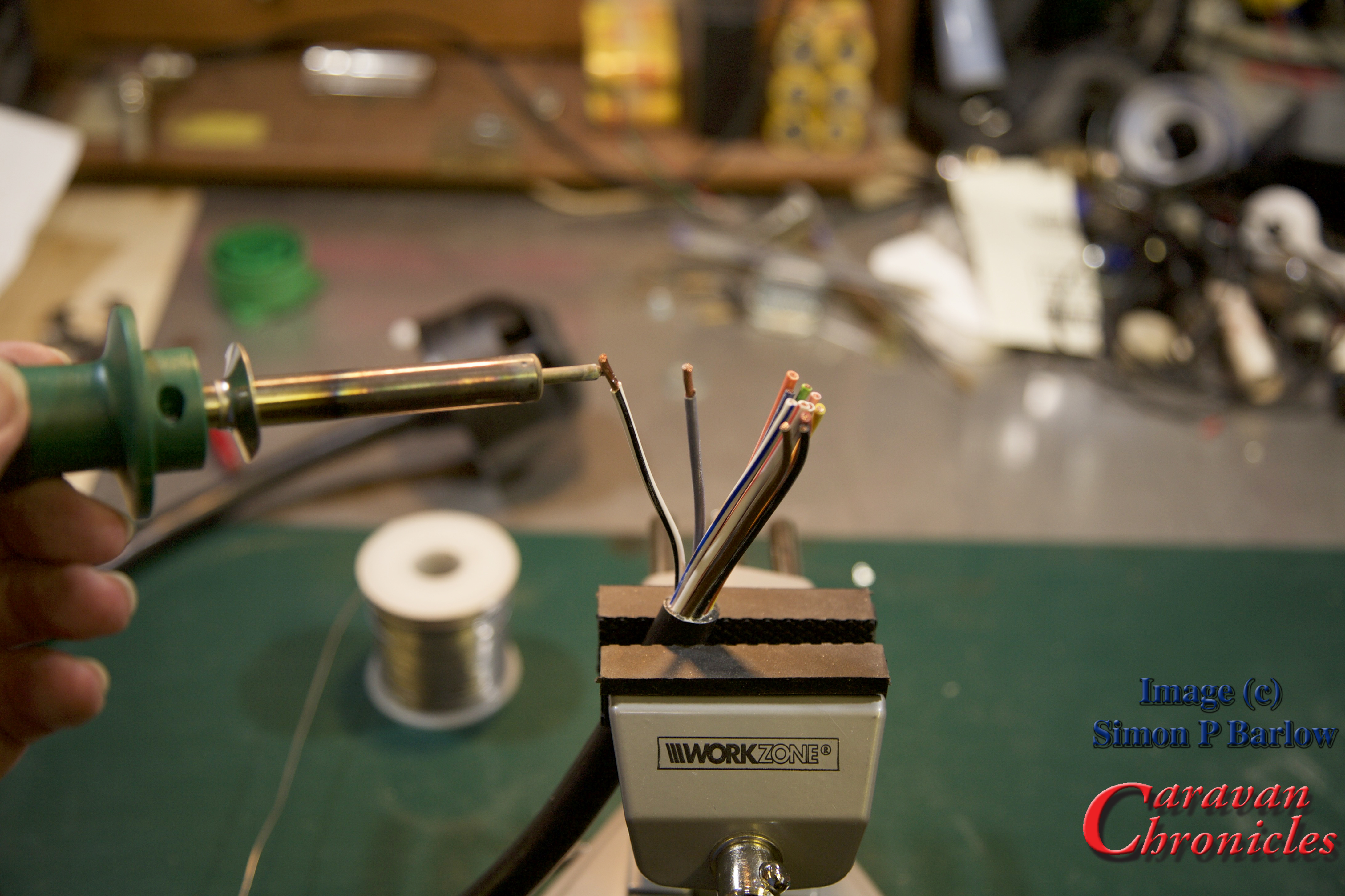
Right back at the start I said there was a compromise – soldering. It’s not difficult to do and achieve and end up with a professional result.
Practice makes perfect and its worth having a go on a scrap length of cable first.
Here’s a few of my tips for successful soldering:
Don’t apply too much heat to cause the insulation to melt (turning down the temperature of the soldering iron or reducing the contact time between the soldering iron and cable helps)
Don’t try to melt solder onto the tip of the iron and run it in to the cable you will burn off the flux too fast… instead touch the solder onto the hot strands of the conductor. Capillary action will pull solder into the strand bundle.
Don’t allow too much solder to be drawn in. You are looking for just enough to still be able to make the outlines of the strands of cable, not a big ‘blob’ of solder on the end.
The solder should look shiny not dull. If it’s dull, the solder cooled too soon as the conductors were not hot enough, this is commonly known as a ‘dry joint’ the solder sits on the surface of the copper.
Avoid breathing in the fumes given off from the flux and the solder. Solder is an alloy of tin and lead… and the flux is pretty nasty too. ( I have an old computer cooling fan that I use to blow the fumes away if I’m doing a lot of soldering).
If you have made the soldered cables too long, you can always trim them back to the correct length. Soldering all the conductors in a caravan cable like this usually takes me no more than five minutes from start to finish.
A few practice runs will soon get you producing good results.
Finally to finish off, I usually give the finished connections a spray of ‘liquid plastic’. It comes in an aerosol can and when sprayed on form a thin plastic coating over everything. You can usually find it in motorbike and automotive shops for waterproofing electrics and HT leads.
It easy to get a good professional result, and I still can’t understand why some tow bar fitting companies don’t either crimp or solder their connections. They usually do when it comes to connecting the other end of the cable to the vehicle. The cynic in me wonders if they are hoping for repeat custom when sockets or plugs start to have problems in the future.
I have been asked where you can purchase some of the products featured above. Here are the links to the products in the Amazon store. If you click on the links and purchase the items, a few pennies will go to helping the cost of running CaravanChronicles.com
One of Caravan Chronicles long time readers and supporters, Colin “Snowy” Snowden, has sent me an excellent article he has written covering all aspects of upgrading pre September 1998 UK caravans to the 13 pin Euro Plug.
It’s very comprehensive article and goes into detail about the various problems and colour codes that were used and cover some of the changes that are required, habitation relays and details the steps required to actually do the upgrade with steps on fault finding.
If you have a pre September 1998 caravan and are thinking of replacing the original 12N/12S wiring with a 13 Pin plug, it’s an essential read.
Colin has included contact details in the article, but if you have any questions that the answers might be helpful to others as well, you could also post them in the comments section below and Colin will be able to answer them.
One of the questions that I’m asked from time to time is about the 12 volt circuit from the tow car to the caravan that powers the fridge, is how to find any problems that could be the cause of the fridge not working at its normal capacity. There are a few checks that can be done on the fridge first before having to start to look for other reasons why the fridge is not functioning to full capacity when towing.
I have written hopefully a simple guide to checking the circuit tracing the voltage drops and locating where the problem could lie. It will take some time and a basic understanding of how to use a multi-meter is required but it should either help you find the problem(s) or confirm that there is nothing wrong with the wiring and you can stat to look for other possible issues.
There is a lot of confusion over what the differences are and when to use each one. So what are they? A relay is just a simple switch that allows a low power electrical circuit to turn on (or off) a high-powered electrical circuit. An SCR or Split Charge Relay is a switch that senses voltage and switches over from one circuit to another at a pre set voltage. Finally a VSR – Voltage Sensing Relay is similar to an SCR but turns on and additional circuit at a pre set voltage. So what do you use each one for?
Split Charge Relay – SCR
These are usually installed in 4 x 4’s that have a lot of accessories fitted especially electrical winches. The general idea is the winch is powered from a second battery so that using the winch should never flatten the main vehicle starter battery. As the winch uses a lot of power, it is necessary to be able to recharge this battery as fast as possible using the output from the vehicle’s alternator, so once the vehicle starter battery is fully charged, the output from the alternator is switched directly over to the second battery. Modern SCR’s are usually all solid state and some times have a bypass switch allowing both batteries to be directly connected for either starting the vehicle if the starter battery is flat or to allow the winch to be powered from the starter battery in emergencies.
SCR’s are normally solid state, I have shown it as switches to make it clearer. Note: I haven’t shown any fuses or earth (neutral) cables. Never use the vehicle body as a conductor, always install correctly sized earth (neutral) cables.
How do SCR’s operate?
If you look at the drawing above, you can see the alternator output goes straight to the split charge relay. In normal operation the relay connects the output of the alternator to the starter battery. Once the engine is running and the relay determines the starter battery is fully charged, it switches the output of the alternator to the vehicle accessory battery. If the voltage on the vehicle starter battery drops, the relay switches back. However, these relays are slightly more sophisticated and have the ability to dual feed – i.e. charge both batteries at the same time or the ability to link both batteries for either vehicle starting or to power accessories under extreme load… heavy and prolonged winching for example. Expect to pay serious money for a good quality SCR with a remote bypass facility and battery monitoring.
A true ‘split charge relay’ is not suitable for charging your caravan leisure battery, but could be used for charging leisure batteries in motorhomes.
Voltage Sensing Relay – VSR
Voltage sensing relays were designed to sense the tow vehicles battery voltage and when the battery is sufficiently charged switch on a second circuit, usually the power to the caravan’s fridge. Some of the more sophisticated VSR’s allow the setting of the voltage the relay will operate at. The biggest draw back with these is if the electrical load with the tow vehicle suddenly increases – turning on the headlights, heated windows, air con etc, they can turn off the circuit to the caravan’s fridge until the electrical load is removed. It is for this reason they should be installed with an indicator light on the dash to confirm that they are actually supplying the fridge. With a caravan, if there isn’t a feed to the fridge, the habitation relay will not operate and therefore the caravan’s leisure battery will not be charged.
VSR’s can be a mix of solid state and mechanical switch or all solid state. Again, I have not shown fuses or earth (neutral) cables for clarity.
VSR’s work on the principle that they monitor the vehicles electrical voltage. The VSR’s sensor detects the voltage change when the vehicle battery is fully or near fully charged, it closes the contacts connecting the leisure battery in circuit and allowing it to be charged. However, if the vehicle voltage drops for some reason, the relay will open disconnecting the leisure battery.
Problems with VSR’s
Most of the time they are installed when the rest of the towing electrics are installed and are usually located behind a panel in the rear load area of the vehicle. Because of this, it is rare to see one that has a dashboard indicator light installed to show when it is ON and charging your leisure battery and consequently switching over the habitation relay allowing your fridge to work. The second problem is when they leave the factory the voltage that they are designed to switch on at is set at the correct level if it was installed near the vehicle battery. As it has been installed some distance away, the length of cable between the battery and VSR has its own voltage drop – dependant on length of cable and current through it. So one fault that is often reported is that the relay ‘vibrates’ or ‘chatters’. This is caused by the voltage drop on the connecting cable increasing below the “trigger voltage” when the leisure battery is connected and the relay is simply turning on and off repeatedly. Like most things you get what you pay for and the more expensive VCR’s have a timer circuit built-in so that they only switch over after a pre-determined time.
But wait…. there’s more!
Modern vehicles are sophisticated bits of engineering, electronics and software. In order to reduce emissions a lot of manufacturers removed things like hydraulic power steering pumps and air conditioning pumps and replaced them with electrical motors. This removed mechanical load from the engine and reduced the weight. The trade-off was the vehicle needed more electrical power, so larger alternators were fitted. As power steering and air conditioning wasn’t needed all the time and in order to prolong the life of the vehicle battery, the alternator is now controlled by the software in the vehicles ECU. So when the ECU detects the vehicle battery is fully charged it reduced the output of the alternator by reducing the voltage and therefore reducing the load on the engine and hence reducing engine emissions. If you have a VSR fitted, this drop in the vehicle voltage will stop the VSR working as it was intended to do. So even if the VCR has a timer circuit, it can still fail to work as intended.
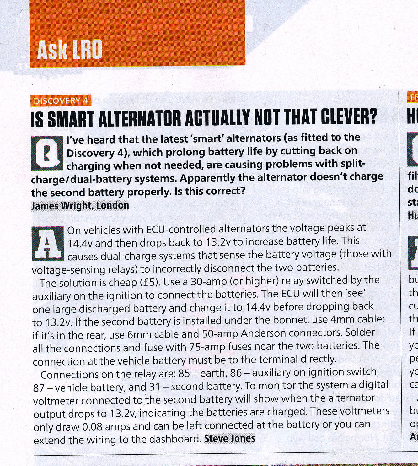
Theres is an interesting letter posted in the September 2013 issue of Land Rover Owner magazine:
Article appeared in Land Rover Owner International September 2013. (c) LRO / Bauermedia
How can we reliably charge the leisure battery in modern vehicles? Well the clue is in the article above. If we can fool the tow vehicle to ‘see’ the leisure battery as part of the vehicles own electrical system the software in the ECU won’t reduce the voltage until both the leisure battery and vehicle battery are suitably charged.
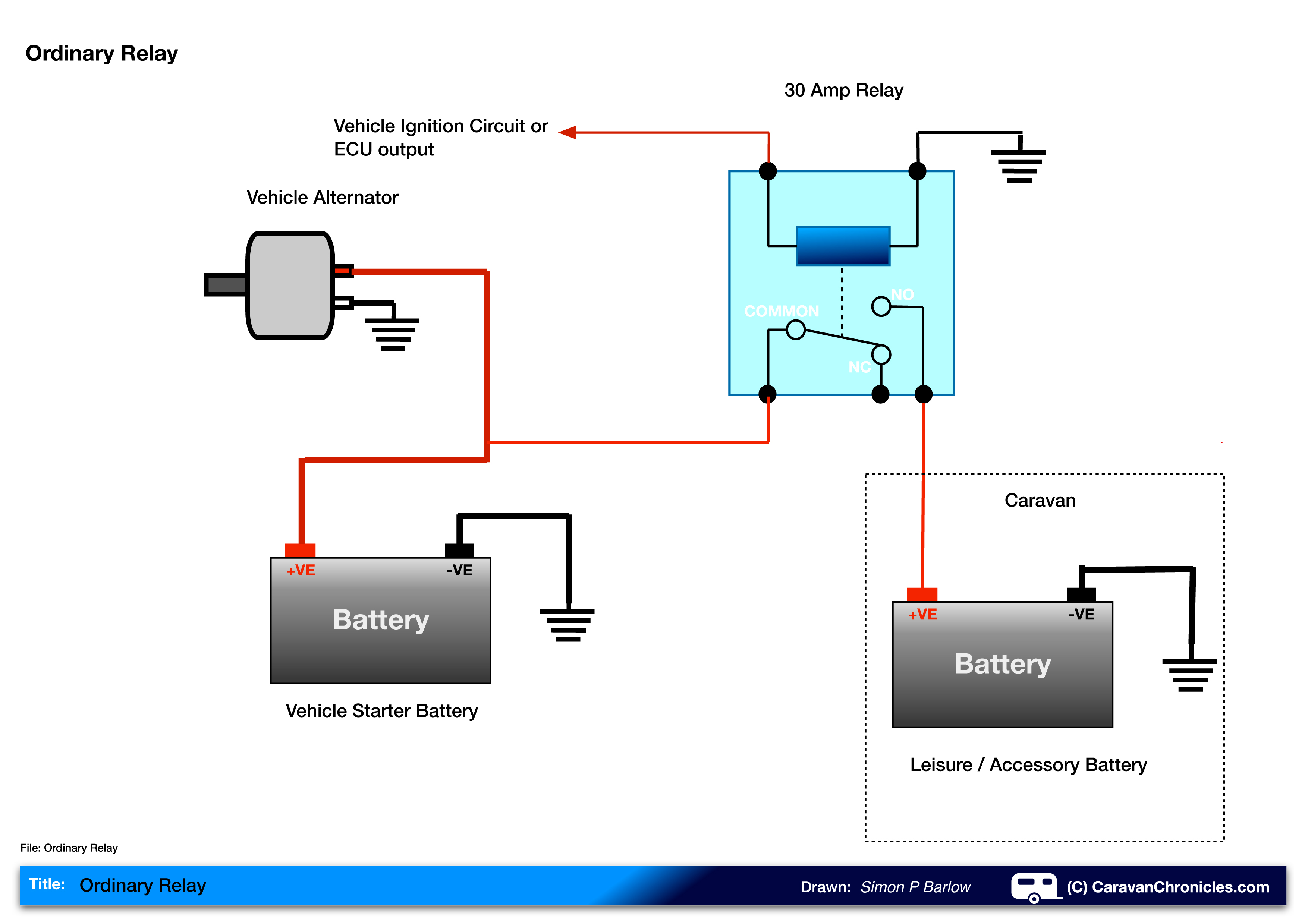
Ordinary Relay
The most straight forward way of providing the leisure battery with a suitable charging circuit is also the cheapest. A simple 30 Amp 12 volt relay can be bought for a few pounds and it will be a reliable way of charging your caravan’s leisure battery.
Ordinary 30 Amp relay. Again, I have not shown fuses or earth (neutral) cables for clarity.
The circuit above shows an ordinary 30 Amp automotive relay being used to switch the leisure battery charing circuit. The relay is controlled by the ignition circuit, so when the engine is running the relay is energised and the leisure battery is being charged. As the leisure battery is in circuit all the time the engine is running, the vehicles software in the ECU ‘sees’ just one big battery and will keep the alternator voltage high enough to charge both batteries fully before reducing the output in energy-saving /emission reducing mode.
Some vehicles including a number of Land Rover’s actually have a connection on the main fuse board specifically to control this relay.