
Heres a quick guide to basic fault finding on the towing vehicles 13 pin socket.
I’ve written this simply as I can in easy basic steps so that hopefully anyone with a little understanding will be able to ‘help themselves” as much as they can before having to ask for assistance.
 I’ll assume you have a digital multimeter and are able to use it to take voltage readings. If you are unsure how to use your multimeter, have a quick read through the instructions supplied with your multimeter. As meters vary on the switch positions, you need to check that it is set for reading DC (Direct Current) VOLTS and can read voltages up to 20 volts.
One of the first things is safety. As you are working close to the rear of the vehicle, make sure the hand brake is on.
As the 13 Pin socket has a flap covering it, it is easier if you can find some way for holding the flap open. I use a length of string looped over the rear wiper arm and down to the socket flap. You could use a bungee cord in a similar manner.
You need to find a suitable earth point on the vehicle to connect the negative (black) lead of your multimeter to. Sometimes the tow ball itself can be used, although this is not always reliable and it’s best if you can find an earthing point in the rear of the vehicle that wiring in the rear of the vehicle is connected to.
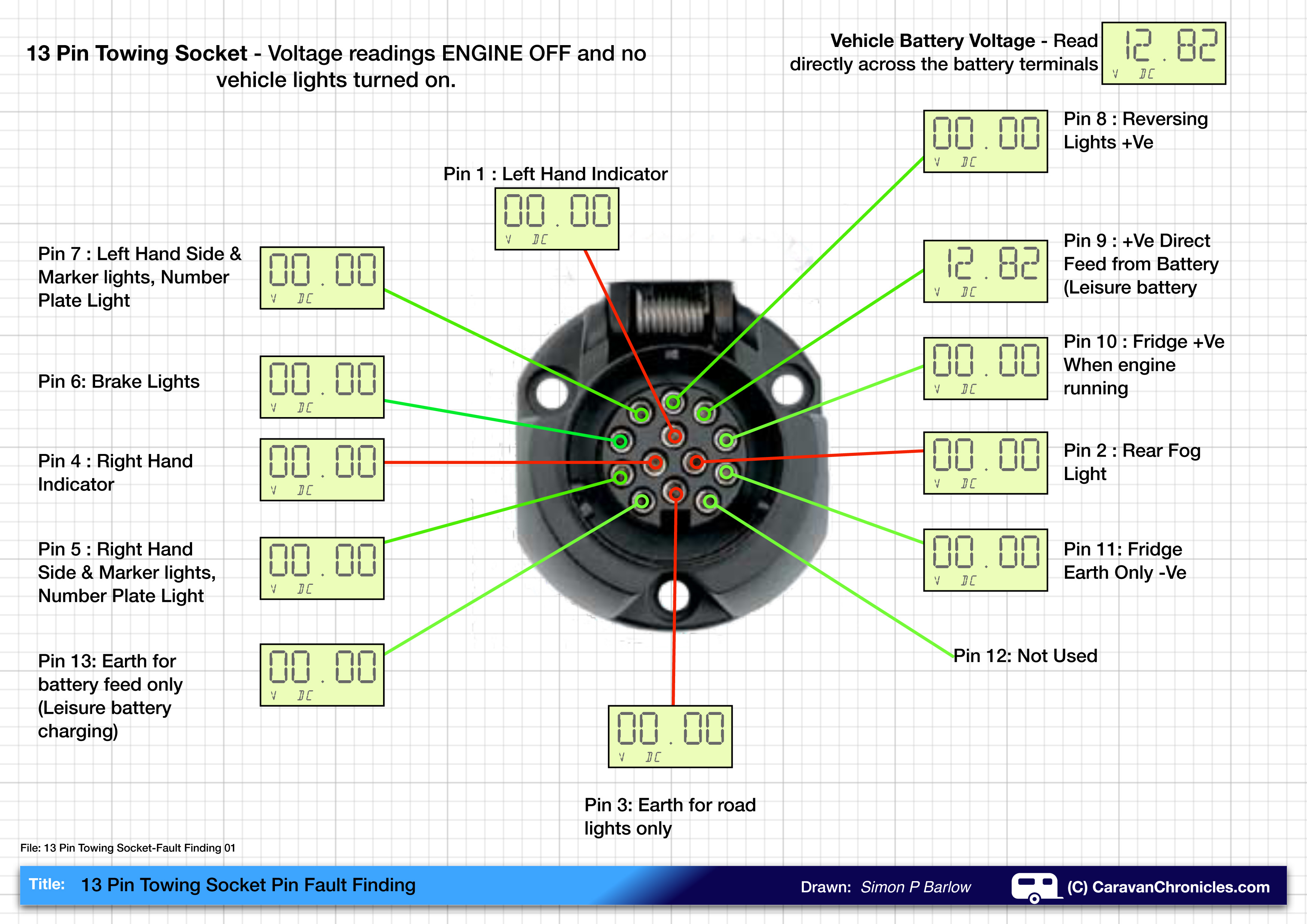
The first test is carried out with the engine off and the multi-meter set to read “volts DC” to obtain a ‘reference’ voltage. The ‘reference’ voltage is obtained by connecting the multi-meter directly across the battery terminals. In our example below, we have a reading of 12.82 volts.
With the engine-turned off, and the negative test lead (black) of our multimeter connected to the earth point in the vehicle. We now check all the sockets connections individually using the positive (red) test lead. Only one – Pin 9 (leisure battery charging circuit) should have a voltage present on it…..
If all that checks out OK we are ready to move on to the next test.
SAFETY: We are now going to test the socket again, this time with the engine running. As you are working at the back of the vehicle you will be close to the engine exhaust. Don’t do this test in a garage. Always be aware of exhaust fumes. Don’t work at the rear of the vehicle with the engine running for more than a couple of minutes at a time. Again, check that the hand brake is applied.
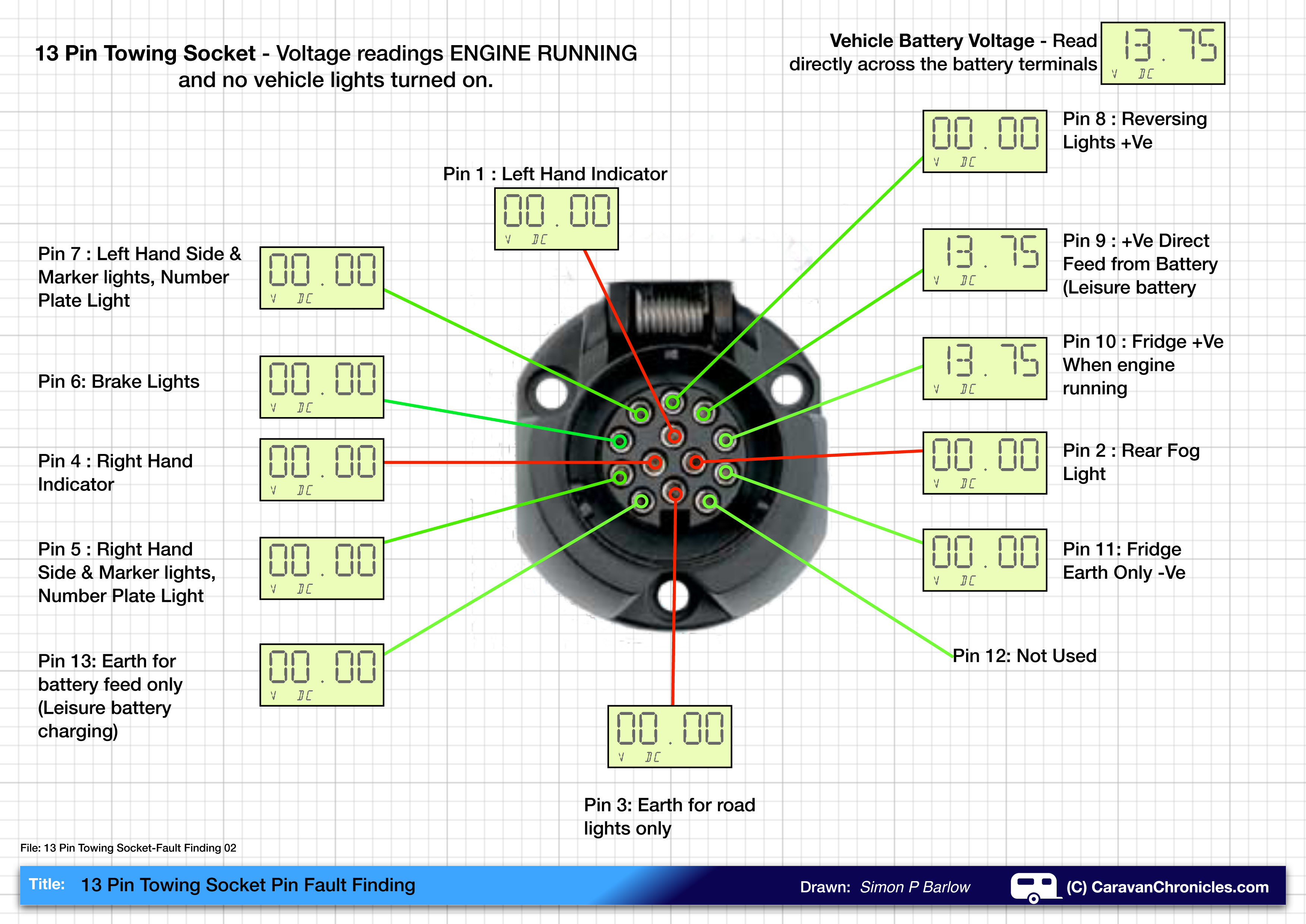
With the engine running we read the ‘reference’ voltage directly across the battery again. In our example now it is 13.75 volts with the engine running.
Returning to the socket once again, connect the negative (black) test lead up to the earth point on the vehicle and go through each pin again. This time Pin 9 should show a voltage as well as should Pin 10 (Fridge circuit) We have now checked that with the engine running, no other circuits should be operating except pins 9 and 10.
NOTE: On modern cars, especially ones fitted with factory towing electrics, the vehicles Electronic Control Unit (ECU) might delay the turning on of the fridge circuit until it detects that enough charge has been put back into the vehicle battery after starting the engine. If you first test Pin 10 and don’t get a voltage reading, wait a few minutes with the engine idling and re-test.
OK… turn the engine off and get some fresh air!
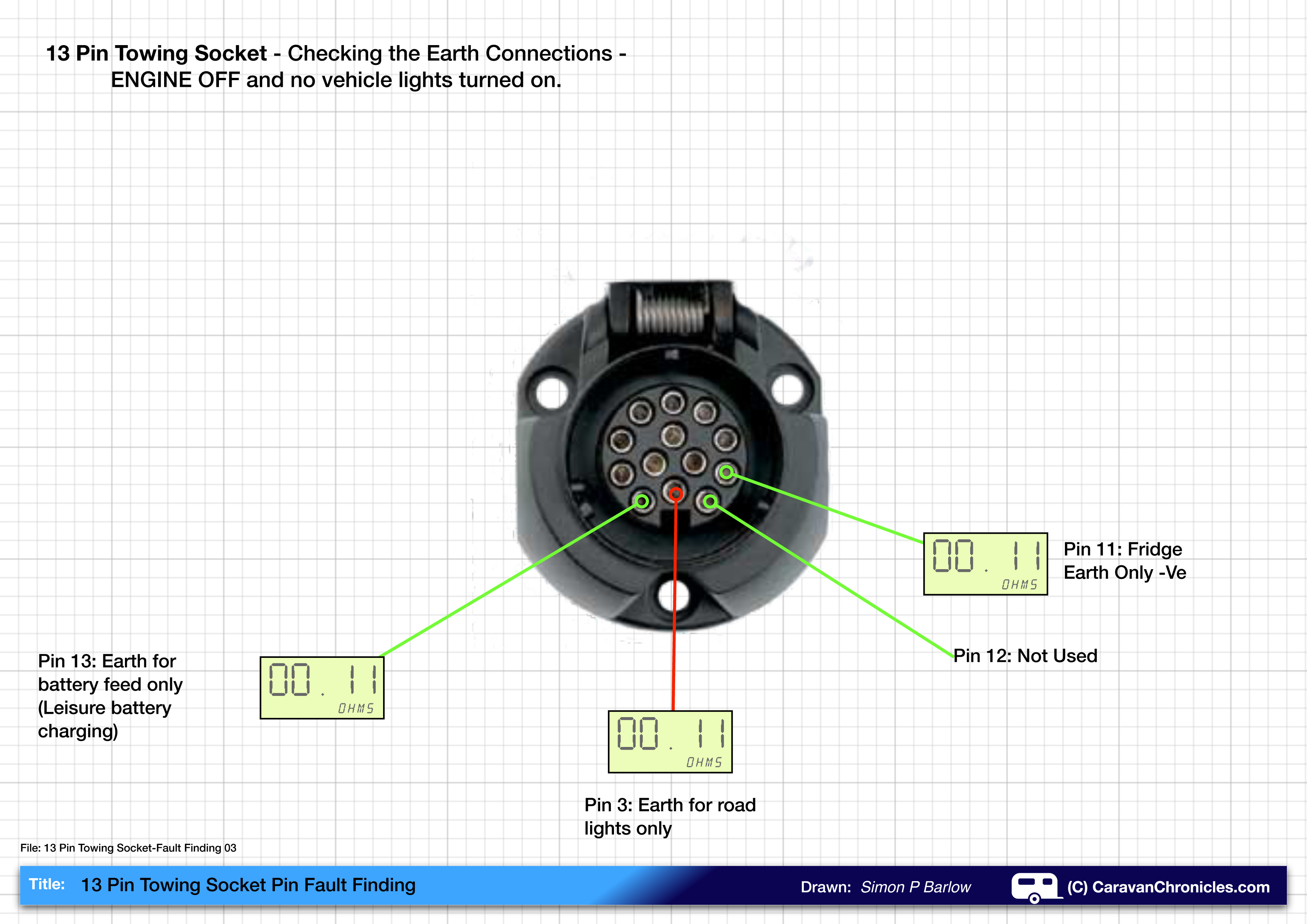
That’s main two caravan supply feed’s checked. Now we need to check the neutral (earth) return path for each of the circuits. The three low voltage (12 volt) circuits are “road lights’, “fridge” and “leisure battery charging”. Within the caravan these three circuits are separate, including the neutral (earth) return path, the only time these three neutrals (earths) come together is at an earth point in the vehicle.
So with the engine off, set your multimeter to read “Resistance” or “Ohms”. To check it is working, touch the two test leads of the multi-meter together, you should get a reading of 00.00 Ohms.
With your multimeter negative test lead connected to the earth point on the car, test each of the three earth connection in the socket… (below). What we are looking for here is the lowest reading. In our example we have a reading of 0.11 Ohms. It is possible to get a reading of 0, but it is more likely to be just above. If it reads 0.5 or upwards, it is probably a bad earth connection. Check your meter’s connection in the car and re check. If the reading is still high, you need to find the earth terminal in the vehicle for the cable that you are testing and give it a clean. It might mean undoing a nut and using some fine emery cloth to remove any dirt from each terminal and possibly rust around the base of the terminal post.
With the test above completed, we are now confident we have good earth connections and the leisure battery charging circuit and fridge circuit are operating correctly.
The next test is for the road light connections.
For this it is really helpful to have an assistant to turn on and off all the lights when required.
SAFETY: make sure they understand that you are close to the rear of the vehicle, as this test requires the engine to be running.
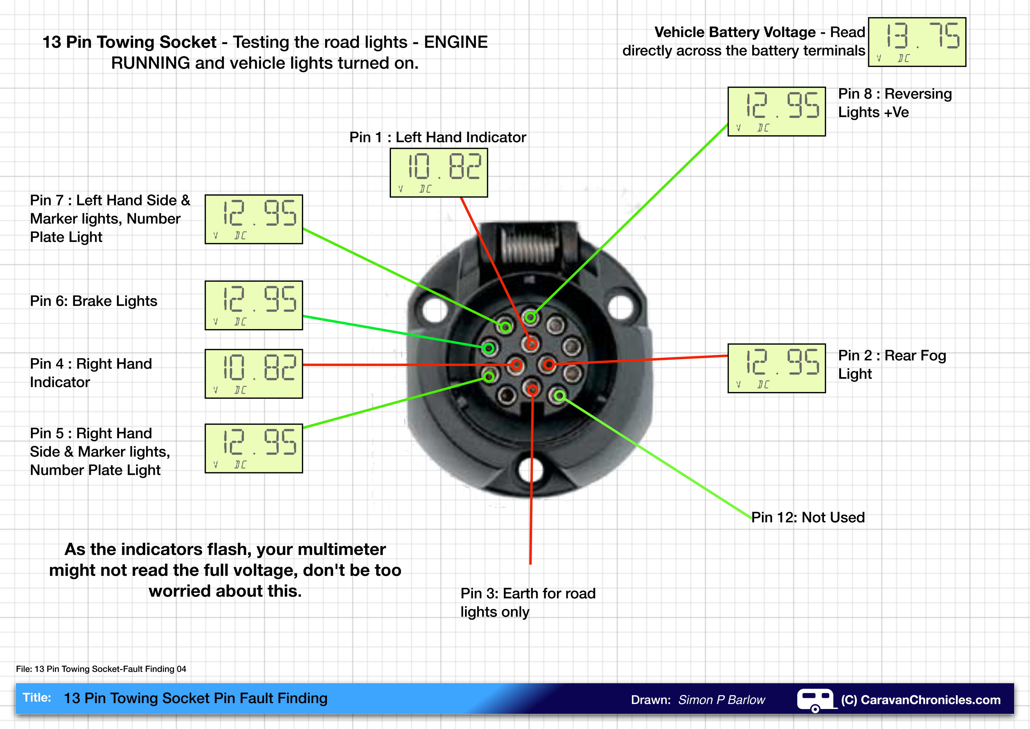
Now we check our ‘reference’ voltage again. Remember to reset your multimeter to read Volts DC. In the example below we have 13.75 volts again.
Now we check each connection in turn. Make sure your meters negative (black) test lead is connected to your earth point on the vehicle. Working logically, start with pin one. There should be no voltage present, now ask your assistant to put the left indicator on. As this is an intermittent voltage, you might not read the same as the battery ‘reference’ voltage as the meter might not be able to register the full changing voltage, so it might only rise to 8 or 10 volts before going back to 0 and repeating. As long as you get a constant on off reading it’s usually acceptable. Keep going round the pins, connect the meter and ask your assistant to turn on that circuit. Remember, the rear fog light will need the headlights on.
When you get to check the reversing light, this MUST for Safety be done with the ENGINE OFF but the ignition turned on. DO NOT ATTEMPT TO CHECK THE REVERSING LIGHT CONNECTION WITH THE ENGINE RUNNING! – I don’t want you to get run over!
Put the test lead of the meter into Pin 8 and ask your assistant to select reverse. You should be able to read the voltage.
After the above tests have been completed, connect up the caravan. If any faults exist, its likely that a fault is with the caravan’s wiring.
If you have a fault on your 13 pin socket, by now hopefully you will know exactly which circuit it is on. If it is the road lights, then the next step is to check the fuses within the vehicle.
If a fault is found with the leisure battery charging or fridge circuits, then more investigation is required. Checking the fuses in the vehicle for these is a starting point, but it may involve tracing the wiring back to find the relays that control these circuits and I would recommend you consult a qualified professional.
A Quick Note about Pin 12…
Although on most of the drawings I show Pin 12 as not being used, this is actually incorrect. Pin 12 is used for trailer detection on some vehicles. How it works varies from vehicle to vehicle and obviously not all vehicles use it. Generally it is connected to the vehicles ECU system. The 13 pin plug on the trailer has a link between Pin 12 and Pin 3 (road light earth) so when you plug-in the trailer or caravan, it ‘shorts’ pin 12 on the towing vehicles socket to earth and the vehicle’s ECU detects this and activates any Trailer Stability Program on the vehicle. The full ISO standard is ISO 1446 for 13 pin connections.
You might like to also read:
Caravan Road Lights – Basic Fault Finding
Caravan Road Lights – Tracing A Fault
S
If you want to download the drawing above, these are in PDF format so you can add them to your iPad, Tablet or eReader…
13 Pin Towing Socket – Fault Finding 01
13 Pin Towing Socket – Fault Finding 02
13 Pin Towing Socket – Fault Finding 03
13 Pin Towing Socket – Fault Finding 04
Understanding Watts, Amps, Volts and Ohms – A very basic introduction to some simple maths that allow you to work out power, current and resistance.
Cable Termination 101 – A look at how to achieve a professional quality cable termination
Copyright © 2011 – 2016 Simon P Barlow – All rights reserved


Hi Simon i have a 67 plate x trail with a 13 pin socket.For some reason the rear fog doesn’t work on the vehicle,but dose on the socket.All the tell tell lights are working inside the vehicle.
It has a dedicated wiring loom fitted.
Regards Paul
Hi Simon, I have an Audi q5 towing vehicle with 13 pin socket and Jayco caravan with 12 pin. The caravan has ESC and fridge but no battery. On inspection of the 13 pin socket, pin 12 seems to be used for electric brakes with pin 11 being an earth (return earth for electric brakes ?) . Pin 9 is permanent live ( fridge) and 13 earth . There does not seem to be a circuit for the caravan ESC … pin 10 has no wire connected to it.
On the 12 pin plug , pin 2 is the caravan ESC with larger than normal black wire , pin 9 is fridge and 10 is earth. Pin 3 is a larger than normal earth wire .
I have tried to wire my own adaptor to suit this but am concerned I may have it wrong.
Any advice would be welcomed
Hi Tim
The correct wiring configuration for a 13 pin socket is: (based on the ISO 11446 Part 1 standards)
Pin 1 – Left Turn Signal
Pin 2 – Rear Fog Lights
Pin 3 – Ground for road lights (pins 1 to 8)
Pin 4 – Right Turn Signal
Pin 5 – Rear side lights, Side Marker Lights and Number plate Light – Left side of trailer
Pin 6 – Brake Lights
Pin 7 – Rear side lights, Side Marker Lights and Number plate Light – Right side of trailer
Pin 8 – Reversing Lights
Pin 9 – +12 volt permanent supply for leisure battery charging
Pin 10 – +12 volt ignition lock supply for fridge (and activation of habitation relay)
Pin 11 – Ground for pin 10
Pin 12 – not used
Pin 13 – Ground for pin 9
The trailer ESC should be wired to pin 10 so it only powers up when the engine is running, some require a permanent 12 volt supply for actual activation so this should be wired into he trailer battery. The signal to turn on will come from pin 10 when the vehicle engine is running but the operation of the unit is from the on board battery. You need to check all this as some ALKO ATS systems are different.
Thanks Simon – unfortunately there is no wire connected to Pin 10 in the Audi socket so I cannot connect anything to it. And Pin 12 on the Audi activates the electric brakes. There is no on board battery in the caravan either. So I can only connect ESC to Pin 9 which is used for the fridge – unless I run a whole new circuit such as an Anderson to run the ESC or find a way to connect Pin 9 to fridge and ESC but I am concerned it might draw too much current for the Pin 9 circuit.
Most German car manufacturers only wire the 13 pin sockets with the fridge circuit missing as continental Europe don’t tend to power fridges when driving… and a lot don’t have leisure batteries either. Only in the UK do we wire everything as standard. There are OEM kits available that provide the missing circuits for OEM and factory German vehicles.
The 13 pin plug and socket is capable of passing around 16 Amps (it’s rated to 20 Amps per pin) but the limitation is the size of cable (2.5mm2 for the power circuits and 1.5mm2 for the lights) and the voltage drop over the distance from he front of the vehicle to the caravan or trailer.
You can just about wire 4mm2 cable into the terminals on the socket but it depends on who made the socket as to what size cable to terminals will accept.
As European caravans don’t have electric brakes I have little information on their requirements. My 5th wheel has electric over hydraulic (the brakes are all hydraulic and operated via electric pump) and it’s has its own 75Ah 12 volt battery on board and a separate lead and plug carrying 6 wires to the vehicle.
Thankyou
I have a hobby 495 UFE as there are no batteries on the hobby caravans would the pins 10 and 11 power the fridge. And would pins 9 and 13 power the 12 volt for the interior lights and could I put a leisure battery in this power line. Hope you can help me
Hi David
Hobby caravan have a fairly intricate 12 volt system controlled via a master unit. As far as I am aware you would need to fit an additional module that will allow the installation of a leisure battery and run charging and the fridge from the vehicle. I don’t think it is an easy option to add these without the unit from Hobby.
Thank you for your help I will have to look into this
Hello Simon,
I have a 2013 VW Touareg with a factory fitted towbar, connected to a Eriba 546. Everything works fine except the caravan battery charging. I checked the car socket and I do have 12V on pin 9, but the pins 10, 11 and 12 are missing. I’ve connected a different car (factory socket, missing just pin 12) to the caravan and the charging is working fine.
Where could be the problem?
Are pins 10 and 11 related to the leisure battery charging function?
Any advice from you will be appreciated.
Greetings from Romania.
Hi
Pin 9 is 12v feed to the leisure battery and pin 13 the negative return for the measure battery, so you need to make sure that pin 13 is earthed properly in the vehicle.
Pin 10 is the 12v feed for the fridge and pin 11 the negative return for the fridge.
there should be three negative pins – pin3 for the road lights, pin 13 for the leisure battery and pin 11 for the fridge. In the Eriba these negatives are not connected together so that a fault will not overload any one pin. You need to check these are earthed properly in the vehicle.
It is common in some countries not to install the fridge circuits on the vehicle so sometimes they install the socket with pins 10 and 11 missing.
Pin 12 is not used, it was originally designed for electric trailer braking but never implemented in Europe.
Thank you for your answer, Simon.
I found the problem. In caravan I have a Schaudt CSV 409 charging system and his integrated booster doesn’t work only with power from pin 9. He needs power also from pin 10 to action the booster relay. I received this info from the manufacturer and he gave me also the wiring diagram.
Now I have to decide if I will add those two wires on car or I’ll stick with the solar panel for fridge, while driving.
Hello Simon, I have a 2016 Kia Sportage and connect to a 2012 Swift Charisma via the standard 13 pin socket. With the car engine running the display panel in the caravan shows the voltage from the car at about 14v and the caravan fridge powers up from the car battery but after about 40 seconds both shut off, you can hear a relay click. Then about 30 seconds later the relay clicks again and the they both power up again only to shut down 40 seconds later. The whole cycle then repeats continuously. I have so far replaced the relay/fuse panel and the display panel in the caravan. I connected my car to another caravan which has the double 7 pin connectors via an adapter cable and that caravan displayed E4 meaning low car voltage. Do you have any idea what might be happening please or suggestions for tests?
Many thanks
Nick
Hi Nick
First thing that comes to mind…. the click you hear is probably the habitation relay which turn on the supply from the vehicle to the leisure battery. This relay is controlled by the supply for the fridge coming from the vehicle. Normally the vehicle will only turn on the feed to he fridge once the engine is running. If the vehicle has a smart alternator (Euro 5 or Euro 6 engines) then as the load demands in the vehicle change the vehicles computer can turn off the supply to the fridge… especially if you have stop/start engine technology.
The other thing could be the vehicle turn on the fridge supply which then in turn allows power through the habitation relay to the leisure battery. If the act of doing this drops the vehicle voltage below a certain level then the vehicle may turn off the fridge supply as it sees it as an excessive drain on the electrical system…. it will try again a short time later, and so on.
Showing 14 volts is one thing, but under load this may drop 3 or 4 volts if there are any bad connections or corroded cable.
Another one to check out is the engine earth strap. On modern cars the engine is earthed via a strap or cable to the chassis….. and somewhere else the chassis is earthed to the battery negative terminal. These connections tend to corrode in part due to the high current drawn by the starter motor. One of the first things to check is the condition of these. I usually always add an additional earth cable from the alternator mounting point directly to the battery negative post. This always improves charging and reduces a number of other likely electrical issues on the vehicle. It’s a fave mod of the hi tech audio guys… one of the first things they usually do.
Thanks for your input, I’ve have instigated a return with the vendor – faulty or not, it doesn’t work on my car so is U/S. Will forward the details to Maypole later to see if they have a comment. Its the second one I’ve tried, from different vendors so is unlikley to be a fault with a production batch!
To make life easier I decided to get a Maypole 13-pin socket tester, which of course will also tell me if the power pins (9 + 10) are operating – all from the comfort of the driver’s seat!
Now I know all my lights work correctly when I connect the caravan, or my trailer board, to the car’s socket, including the reverse and rear fogs when the ‘van is connected.
But the tester? Well, It does not show outputs from pins 2(FogLights), 7 (LH Tail), 8(Reverse). All the others (including Pin 5 RH tail) show correctly, except that Pin 6 (Stop lamps) also cause pins 1 and 4 (Indicators) to flash rapidly.
The caravan is a 2012 bailey, so I wouldn’t expect the LH and RH circuits to be interconnected. Even if they were that would not explain the issue with the tester not showing the reverse or rear fog.
So before I send the tester back as being faulty, is there something I should know?
Thanks – Richard
Hi Richard
Not all testers are created equal. I have seen a number that although fitted with a 13 pin connection only test the pins associated with a 7 pin connector and don’t include the circuits that would be originally connected with the 7 pin “S” connector. There are some really cheap testers out there that are branded up and sold for more money than they are worth. You are right Bailey don’t combine left and right tail/marker lights in the caravan.
I had much the same problem with an MoT test, I hitched up the caravan and took it back to the test station to prove it was their “MoT approved” tester that was at fault. I always plug in the 13-7 pin adapter these days!
Hi Bill
I have had countless people contact me reporting their 13 pin socket “failed” the MOT test but works perfectly with their caravan. The 13 pin testers on the approved list for MOT test equipment needs revising.
Thankyou your details and diagram are spot on and very easy to follow, ok you can use a 21watt bulb if no multimeter, to test the curcuits which I have used in my last 40 years of caravanning . But great information. And very helpful as most diagrams show the rear of socket so diagram for testing is wrong confusing ?
Hi, Thanks for a very helpful explanation. I have a problem, and would be very glad of some help. I have a 2017 Kia Sorento fitted with a kia tow bar and electrics kits, ( both the basic kit for road lights and the extra kit for the permanent live and fridge circuits) I have an Eriba 530 caravan. When the caravan is plugged in to the car, everything works except for the caravan reversing light and rear fog light. I have tested the relevant pins in the 13 pin socket with the following results:-
fog light 0 volts under all circumstances
reversing light 0.3 volts when the fog light is switched off,
0.6 volts when the fog light is switched on.
Thanks in advance for any advice you can give
Hi Alwyn
Couple of things come to mind, when the caravan is hitched up and plugged in to the vehicle, do the vehicle reversing lights and rear fog light still work?
If they don’t then that would lead me to suspect that the vehicle was coded correctly for the basic kit which might have been for the basic road lights (The old 7N trailer plug wiring). The reversing light, fog light, fridge and leisure battery charging were originally handles by the 7S plug… so the additional kit might also include reversing and fog lights as well as the fridge and battery charging.
I have seen where the additional kits have had the reversing and fog circuits wired directly to the vehicle lights as a short cut, not to the control box…. and as the vehicle is programmed not to activate the vehicle fog light or reversing light when a trailer is detected as being plugged in the trailer fog and reversing lights don’t work. I have seen this a few times on rear bike carriers that have light boards… when thy are plugged in the fog and reverse lights don’t work on the trailer board.
Would be worth checking to see if this was the case before chasing anything else.
Thanks for the rapid response. When the caravan is connected up to the 13 pin socket, the car rear fog light and reversing light still work.
In that case, I’d suspect the vehicle had not been coded for trailer lights. Most vehicles will operate the standard road lights on the trailer before coding – tail, side brake. However when coded it usually turn off reversing and fog on the vehicle with the trailer connected and on most vehicles the ABS / ESP / Traction Control systems are altered with the trailer connected. You can usually get this checked at a dealer or tow bar installation company. Some OBD scanners will read and display the settings for towing when plugged into the OBD port but I’m not sure with Kia vehicles if this can be displayed.
To the best of my knowledge no new coding of the car is supposed to be required.
Just had a quick look on line… you need to download the trouble shooting guide ( english one here:- https://www.mobisparts.eu/de_de/custom/mobis_accessories_db/details.php?part_no=xx62xADExxxx&brand=K&carmodel=49#
You can test the output of the canbus control module and the wiring between the control module and 13 pin socket.
Hi,
I just installed a used factory Ford towbar and electrics (including CAN module) on my 2012 S-Max and I’m not getting any light function. Grounds are good and I have 12 volts on pin 9. With the ignition on my test light blinks weakly on all other pins (about 4Hz continuously with volt meter cycling 0 to 6V) and does not light up brightly like on pin 9. I also tested it with an actual trailer and had no light function. Any suggestions before I head to the Ford dealer? My understanding is that the lights should work even without any programming. Maybe the module needs to be reset because it was previously used in another car?
Thanks
As I understand it the vehicle must be coded for trailer use and will not recognise the trailer module until it’s updated. Only some Fords will activate the 7 pin electrics for towing without coding. All 13 pin modules need coding to the ECU.
Just an update… took the car to Ford today and after programming everything works! A little frustrating to have to do that but it was quick and only 40€.
Great news….
followed your sequence of wiring for 13 pin plug but find it has no pink or correctly striped wires for pins as listed, who changed the colours and to what do each belong ?
Hi
Unfortunately not all manufacturers follow the advised colours. Some cable is used that has different cover sequences originally intended for different uses.
Once again,
I thank you for your advice and will continue my uphill challenge .
Jason
Hi Simon,
I’ve just carried out the earth check on the caravan plug as per your instructions, pins 3-11 OL, pins11-13 OL but Pins 3-13 0.8ohms, could this be the issue with the intermittent towing lights?, I’ve carried out a Con check from plug to mother board all ok? I’m thinking as its not had its first service yet just get them to investigate or are here other steps I could try?
Many Thanks
Jason.
Hi Jason
Pin 3 is road lights earth so should be separate from the others – pin 11 fridge earth and pin 13 leisure battery earth. I’d expect to see pins 11 and 13 separate as if the earth fails on one of these pins the remaining pin out of the pair would have to carry the load of leisure battery charging and fridge heating element. It’s something I’d look at but I don’t think it has a bearing on the road lights issue.
It’s more likely in my opinion that the vehicle is having issues with the LED road lights on the caravan. I know that there are issues with this caravan and some Land Rovers – I think Sargent Electrical came up with a module to be installed in the caravan to sort the problem out.
If you have the time you could try clipping 10 watt bulbs across each of the circuits… so between pin 3 and 7, 3 and 6, 3 and 4, 3 and 5, 3 and 1. This will put a slight load on each circuit which hopefully the vehicle will ‘see’ and work normally. Its a bit of a faf to do just for testing, I normally do it at the road light fuse panel in the caravan with some small bulbs that I soldered leads with crocodile clips attached.
Hi,
I’ve got a 2020 swift alpine sprite 4, Had a new tow bar fitted on my Peugeot by Peugeot (308 SW) the caravan indicators etc where intermittent, so Peugeot have replaced the tow bar ECU and harness but issue is still there, unless I switch on my side lights on the car then they seem to work ,however the indicators aren’t flashing at a steady rate, is there a check I can carry out on the Caravan 13 pin socket? and do I have to have my side lights on in the car?
Many thanks for any info.
Jason.
This is a known issue with some tow bar units and certain caravans. It can usually be cured by installing ballast resistors on the lighting circuits in the caravan, usually done at the junction where the 12 core cable joins the caravan lighting loom fuse panel.
Normally you should not have to run with side lights on.
Hi Simon,
Great article, has really helped me start to diagnose a problem I have with my Brenderup utility trailer. I’m totally new to towing and just bought my first trailer as I’ll be moving to France with my family soon.
My problem is that for some reason, the reverse light on my trailer doesn’t seem to work. I tried changing the bulb as an easy start but no joy. I followed your article and broke out my multimeter. The 13 pin socket I recently had fitted shows no voltage at all from pin 8 with the ignition on and both car reverse lights glaring me in the face. I checked the other pins on my Civic and they all behave correctly as described in your article and confirmed with visual inspection.
I’m not really sure where to go from here, except to think that perhaps the reverse pin wasn’t wired in correctly or has come loose or something. I presume it takes a feed from one of the reverse lights somehow?
An interesting side note which only just clicked is that when I picked up the trailer the guy from the trailer place said “remember, your parking sensors won’t work when you have a trailer connected.”. At the time I just thought “that’s cool” and drove home. I have now realised that even when the trailer is connected, my parking sensors still operate and go nuts of course, mistaking the trailer for a wall! I’m wondering if this could be a symptom of my problem?
I appreciate any insight you might be able to give.
Thanks,
Ollie
Hi Ollie
With the parking sensors still working and If the reversing lights work when a trailer is plugged in, I suspect the rear fog lights on the car will also work with the trailer connected. I would guess that the towbar was fitted but the vehicle was never ‘coded’ to turn/activate the towing mode on the vehicle. It may be worth checking with the original installer or dealer.
Thanks Simon. I’ll certainly look into the coding issue but my immediate problem is having no reverse light on the trailer. I suppose all I can do is trace the wires back and see when I find voltage! I don’t envy the idea of likely needing to strip out half the boot to get at the wiring though……
I’m not 100% up to speed with Honda’a but I think that there is a multi-pin plug from the tow socket that connects into the vehicle. It may be worth doing a search on your vehicle type for tow bar installation instructions. Usually most manufacturers install guides are on line somewhere. At least it would give you a place to start before starting to disassemble everything.
Hi Simon, many thanks for your excellent descriptions. I have a query – on my trailer I have a 13 pin light bar connection. The left hand night light is not working, but all the other road lights work (number plate and marker light, as well as indicators). It’s not the bulb, I’ve checked. And the wire is on the terminal OK. I am guessing it must mean there is a wiring connection problem somewhere with the night light, and if so, that probably occurs right when that pin splits out to the 3 separate lights it powers? Your thoughts would be appreciated! Thanks, Simon
Hi
You will find that the left hand side lights run fro one pin and the right hand side lights run from another pin in the trailer socket. The number plate light can be powered from either the left or right lights. Probably one pin is not powered.
Pin 5 is right hand marker and tail light, pin 7 is left hand marker and side lights. The number plate can be powered from either.
Hi Simon
many thanks for your quick and helpful response on this. I will take a look and see if I can use a multimeter to work it out. I suspect now that the wiring is loose because other lights using the same pin are working on the left side, eg the marker light.
Cheers, Simon
Thanks for the swift reply. That has helped clarify my thoughts. I already have a 30amp dc to dc on the transporter Aux battery. I think I’ll swap it out. Put the 18amp dc to dc on the vehicle aux battery (75amp AGM) and use the 30amp dc to dc via anderson plugs to the caravan for the 150amp lithium.
cheers
Hi thanks for all the great information.
I am interested in how many amps can be draw down Pins 9 and Pin10?
I realise it is in part wire gauge dependant. I was wondering if there is genarally acceptable amount that manufactures allow for.
Would there be a fuse dedicated to either or both of these Pins?
I am considering putting an Victron 18amp Dc to DC charger in my caravan to assist with charging 150amp lithium leisure battery whilst we are driving, this would help with any voltage drop due to the long distance. We have solar as well.
I’m considering whether to use Pin 9 or run a dedicated cable from my starter battery.
I have a VW 2019 Transport 150kw.
Cheers
Hi Peter
Realistically the best you can usually get from pin 9 and pin 10 is about 15 amps each. I have a Stirling Wildside unit that has a feature that combines pin 10 and pin 9 on the input and gives a constant voltage to the fridge and what ever is ‘left’ to the leisure battery. (Have a read of my series about installing one for more details) This allows me to set a charging profile for my leisure battery depending on battery type including lithium.
Both pin 9 and pin 10 have separate fuses, some installations are fused at 15 amps (my Freelander is) some are fused at 20 amps (My VW Amarok is)
If you are going much above 120 Ah on Lithium it may be time to look at installing a separate charging circuit (as many Australian outfits do) by installing an Anderson connector on the rear bumper wired using 10mm or greater cable direct to the vehicle battery and use a 150 amp relay on the +ve side near the battery to only allow a connection when the engine is running. There are specialist relays designed for this. (Have a look at REDARC products)
On the caravan side a new lead is installed with an Anderson plug to connect to the vehicle using the same gauge cable as on the vehicle directly to the DC to DC charger.
Personally for a 150Ah Lithium battery I’d install a separate charing circuit with Anderson connectors between vehicle and caravan. With 10mm cable this would allow you to increase the size of DC to DC charger to a 30 Amp unit.
10mm cable would AWG #6 meet the spec
A quick conversion would be….
8mm2 is 8 AWG
10mm2 is 7 AWG
13mm2 is 6 AWG
So 6 AWG would be easily in spec.
Brilliant workthrough page, thank you.
have a problem , 2012 Honda crv. second hand genuine bosal towbar, supposed to be plug and play.
all lights work except both indicators. when running through your test procedure if either left or right is selected both pins on 13 plug show 0.30v??? any clues? Ta Rob.
Hi Bob
From memory I think that Honda’s use a low voltage for the “bulb out” detection circuit. Try with a 15 watt tail light bulb. I seem to think that some Honda’s had issues operating with trailer LED lights and required a ballast resistor (or CAB BUS compliant LED bulbs)
Thanks for the reply, tried the lamp test, still no power to left and right indicator pins. Both pins show 0.3 v at the same time when either left or right indicator is selected. Any further suggestions?
In that case it sounds like the vehicle hasn’t had a software update for the towing electrics. Has the vehicle been back to Honda or a Tow Centre to have the update installed? If it has, it may be worth gouing back and asking them to check as the update may not have installed correctly.
Simon I have a problem I use a connector as my car has a 13 pin socket and my caravan a 7. All works fine except when I unplug the car still thinks the caravan is plugged I. The indicators flash twice as fast. If I p.ug the caravan or any trailor back In the indicators work fine. To fix this i have to unplug the trailor/van with engine running then it doesn’t always fix it first time.
Hi Robert
It is highly likely that your 13 pin socket on the car is one with a microswitch that senses when a connector is plugged in. After a period of time the switch can stick so that when you disconnect the trailer plug the car thinks the trailer is still connected.
My solution would be to use an aerosol of something like Boeshield or similar light lubricant (not WD40 as over time this affects the plastic) and spray inside the socket around the outside of the central pin cluster and connect and disconnect the plug a few times.
Hi Simon,
Just bought a used 2014 Peugeot 208. Just happily found out it has 13 pins. Thought it had just 7 pins, but that’s because the previous owner had an adaptor connected. So everything works on my caravan. Just wondering how to turn it off in the car when the engine is not running since the fridge works on 12 volts and there is 14.5 volts coming into to recharge the leisure battery. Also I’m worried about recharging the leisure battery at 14.5 volts for too long. Any ideas. thanks, Michael
Hi Michael
When you turn off the engine, it will automatically switch off the output to the fridge. All 13 pin sockets work this way.
Don’t worry too much about 14.5 volts going to your leisure battery. The voltage drop between the vehicle and battery in the caravan will reduce this and it is highly unlikely that you will do any damage to the leisure battery.
Additionally as the vehicle battery gets to near full charge, the alternator voltage will drop slightly reducing further the voltage going to the caravan.
OK Thanks Simon,
Good, useful, information on your website.
Another question I had, is when my leisure battery in my caravan is being recharged by 230V, its charging at a constant 14.5 volts without trickling down.
Im not sure if something is not working to bring the voltage down after the battery is fully recharged.
How long do you think I can safely recharge it at this voltage without overcharging?
Michael
Which electrical system is it installed in your caravan?
Great explanation and very helpful for those who are not electrically minded. I followed the testing guide which makes the testing of the euro sockets output’s very simple for anyone to undertake themselves. Loads of work from you to put this together.
As you see I did not get run over by my vehicle 🙂 but have some different results to the expected ones and not sure how to interpret them.
1. On the earth checks my meter was at 2.9 ohms and when testing 3.9 ohms for all three. Do I take it that,s 1.0 ohm for my vehicle? This points to a bad earth in a new car?
2. Also on the engine running tests the following were observed pin 1 0.25, pin 4 0.25, pin 5 14.38, pin 6 0.25, pin 7 14.38, pin 9 14.38 and pin 10 14.38 with a reference battery test of 14.38.
The challenge I have is that the fridge will not feed of the car when its running – it acts like there is no current coming through. I have disabled stop-start on the car as recommended in the manual.
Your thoughts appreciated
Paul
Hi Paul
On the face of it, yes I’d say look at the earth side first. The body of a vehicle is not ideal anymore (not that it really ever was!) for providing a return path. Panels are not always steel and not always welded on but glued on. Some are bolted on only after they have been painted. So a good earth path can be difficult to achieve. I advocate running a separate 6mm cable from the battery negative to the earth point where all the 13 pin socket earth leads attach as a supplementary path. One or two installers are now doing this as they know which cars tend to have issues down the line.
The other thing that is slightly suspicious is the test voltages match the battery voltage. Really it would be good if you could test them with a 50 watt bulb connected and check the voltage. You might have a path that is high resistance but tests OK on just the tiny load a multimeter imposes on the circuit.
I have had a new 13pin socket on my vehicle but the offside running lights don’t work. I put a 7 pin converter on both plug and socket and the running lights all came on, any ideas please.
Hi Steve
Some of the 13 to 7 pin converters link pins 5 and 7 together internally as a number of the small trailers under 750Kg and lighting boards only use either pin 5 or pin 7 for the rear tails lights.
If its the off side not working then it sounds like a fault on pin 5 in either the tow socket or tow plug. If using the converter everything works that would tend to rule out an earth/ground issue.
Hello Simon,
The van being manufactured prior to 1st September 1998 has just the two earths which go back to the connector block. A separate one for the road lights and a combined 3.5mm cable for Fridge, Battery charging and internal electrics. Without stripping out a lot of cabinets I cannot get to the back of the fridge to find it’s earth.
Thanks for your thoughts – I will check all again and the towbar earth in the car, and see if I can sort this.
Regards
Steve
Hello Simon, managed to get some voltage drop readings as suggested – same sequence as you suggested above:
1 Fridge On – 0.25, off – 0.50
2 On – 0.23, off – 1.30
3 On – 0.65, off – 0.12
4 On – 0.66, off – 0.17 (was not able to directly find the fridge -ve so used the combined van earth).
So biggest drop in +ve circuit…..
The caravan was manufactured in 1996 (pre 1998 wiring) so when fitting new 13 pin cable and connectors I fitted a 5 pin relay (85/86/87/87a and 30) in the circuit. Seems to operate as it should, but could it be part of the problem?
I will try and get a reading tomorrow on the battery negative to towbar earthing point.
Thanks
Steve
“…combined van earth…” Not too sure what you mean here.
There should be THREE separate earth cables from the caravan to the vehicle. Roadlights, Leisure Battery Circuit & Fridge Circuit. None of these earths should be interconnected in any way within the caravan. The only place all three should come together is at a point in the vehicle after the 13 pin tow socket.
Not quite sure what’s going on… you have a bigger voltage drop on the +ve feeds with the fridge off than you do with the fridge on.
On the leisure battery earth I’d expect to see roughly the same volt drop with the fridge on or off. Similarly with eh Leisure Battery +ve, I would not expect to see much difference which would be accounted for by the vehicle voltage being slightly higher without the 100+ watt fridge load.
Thank you Simon, very quick reply – caught me hopping! I will absorb your advice, do the checks and report back. Thanks again, Steve
Hello Simon, really good explanation – helped me recently when I swapped old black and grey plugs to new 13 pin lead and plug to suit change of car.
Everything worked fine…or so I thought. Arrived back from a week away and the caravan battery was reading only around 12.1v. Charged it up off the caravan on a smart charger to full charge (actually reading over 13v) and reinstalled on the van. Then checked all connections with multimeter. When connected to the car and car running with fridge turned on to 12v (fridge light is on) I read the battery at 12.7-12.9v. With fridge off it increases to 13-4-13.7v (fluctuates). The car battery reads 14.1v while engine running, 12.25v engine off (I know it’s low but I have done a parasitic drain test and it does come back up to 12.5 ish after a few hours (modern cars eh?).
So maybe alternator is not proving enough current to run fridge and charge van battery? But this should not cause the van battery to ‘drain back’ into car? The towbar was fitted when I bought the car, should have a split charge relay fitted?
Any thoughts on how I might procede to solve this?
Thanks
Steve
Hi Stephen
Sound to me like you have a big volt drop somewhere… and first guess would be it is in the neutral (earth) circuits via pin 11 (fridge earth) and pin 13 (leisure batt charging).
Have a read of this: https://caravanchronicles.com/2019/04/03/something-for-your-toolbox/
Then do a few checks. with the engine running and fridge on measure the voltage between these points: (you will probably need to make up a long single core lead for your multimeter)
Make a note of the voltage drop for each of these:
1, Vehicle Batt +ve terminal and leisure batt +ve terminal
2, Vehicle Batt +ve terminal and fridge +ve terminal
3, Vehicle Batt -ve terminal and leisure batt -ve terminal
4, Vehicle Batt -ve terminal and fridge -ve terminal
Repeat with the fridge off and note the voltage drop.
I’ll bet there is a big voltage drop on the -ve side of things with the fridge on compared to fridge off.
This is probably down to less than satisfactory earthing in the vehicle. I have come across this before and my solution was to run a 10mm cable directly from the vehicle battery -ve terminal to the earthing point in the boot of the vehicle. As the tow bar fitters had used the same earthing stud used for the road lights. (Apparently this also cured a ‘crackely’ radio too!)
Great article Simon, really informative.
I’ve just had a problem with my MoT test because the VOSA approved (Sealey) tester showed my 13 pin socket wasn’t working correctly. When I plugged it in to the caravan everything worked just as it should. The car is Toyota with a Toyota supplied wiring kit.
I asked the tester to show me what he had found and sure enough the LED’s on the tester showed the fog light not working and the brakes lighting up both indicators. I think the clue is that the fog light on the car wasn’t cut off by plugging in the tester but it was with the van, so I suspect the car doesn’t recognise the tester as a trailer – probably because there are no lamp filaments to detect.
Any ideas how to get around this without taking my caravan along to the MoT test every year?
Thanks, Bill
Hi Bill
This is a fairly wide issue with the MOT test set’s used by some stations. There are three or four VOSA approved units offered by manufacturers and the older Sealy is one that is known to indicate failures.
I believe that on a couple of MOT tester forums there is a lot of discussion about this issue and they have a list of what test units are OK. I believe that test units produced in 2018 have sorted the problems.
I was told by an MOT inspector that if you remove the tow ball they cannot test the socket as the vehicle is not capable of towing. However I’ve been told all sorts of rubbish by MOT testers over the years and it seems to be all down to their personal interpretation of the rules.
Hi Simon,I have had a friend round and I plugged my van into his car and everything worked as it should .So all probs must be caused by the new electrics.Tommorow I can go back to the towbar fitters and tell them that the faults are in the new wiring.Thanks very much for you help and I will let you know the out come.
Hi Alan
Get them to check for Pin 9 (+ve leisure battery feed) and Pin 10 (+ve fridge feed) reversal or interconnected (shorted) together.
99% confident its one or the other.
I will do.I will be there at 8.00 tomorrow morning .When I told him my faults he couldn’t believe he had caused them.He said my car must be faulty.I explained the car was ok when not coupled to the van.It was nice today to try another car to prove the caravan side was right .Thanks Simon.
Hi Simon,I took my car back to the towbar fitters today.He had it for an hour then rang me to say it was done and was ok on all his test eqiipment.He said the fault was caused by the relay not kicking in.Not sure but I took it home and plugged it into my caravan and everything works ok.At least it is sorted now,I wonder if he checked it with his tester when he finished the first time. Much thanks for your help,Alan.
Thanks for this great info.I have just had my towbar electrics updated to 13 pin from 7 pin on my xtrail.I connect to caravan and nothing happens till i turn ignition,then ATC lights green and everything works ok.When i turn off ignition.ATC still green and fridge is still supplied.Also car built in sat nav and radio still on and car central locking wont work.When i unplug the caravan car radio and sat nav go off and central locking works.Doing your test I find when ignition is off all pin holes are dead.With engine on 9 and 10 are live.Any help appreciated Alan.
Hi Alan
I did reply to your email this morning. I am confident the caravan is back feeding the vehicle and this would be down to the fridge circuit and leisure battery charging circuit being either reversed or connected together when the caravan is plugged in.
excellent stuff. I am self taught and confident with the old 7 pin kit but this is all “new”
Nearly all the faults I see on old and agricultural 7 pin systems are bad earths .” My side lights come on with the stop lamps” sort of tale’
Dear Simon
I have a 7pin trailer with road lights only. It is supplied from a crossed over 13 pin socket on a C-Class Mercedes. None of the trailer lights work. Fuses are ok, Bulbs are ok.
The 13-pin socket’s Pin 5 & 7 consistently deliver 4v. Pin 9 and 10 deliver battery voltage
Voltages do not change with car lights functioning.
Ground resistance of pins 3 & 13 is 0.4Ohms but the earth terminals are all very shiny and new looking.
I presume the car detects current flow between pin 5/7 & 9 to determine if a trailer is connected and then delivers 12v when necessary.
Therefore if my reasoning is correct if I correct a bulb across pin 5 & 9 I should be able to measure voltage on pin 6 when the brake lights are activated? If this does not work then probably there is something wrong with the widgets in the car?
My head is now melted.
Hi Adam
Pin 5 and 7 are the left and right hand tail and marker light circuits and the voltage you are measuring is the trailer detect voltage.
You are correct , if you connect a bulb between pin 5 (or7) and pin 3 (road light earth) the vehicle will recognise that a trailer is attached.
The voltage tests for all road lights must be referenced to pin 3, road light earth. In your comment you mentioned connecting a bulb across 5 & 9. 5 is the right hand side marker and number plate lights and pin 9 is the +ve direct feed from the battery (leisure battery charging circuit). You need to connect the bulb between 5 and 3.
Hi i must just say this is the best post i have seen for testing out a 13 pin socket…many many thanks from all of us not so savvy diy electricians 🙂
My 13 pin plug is working the lights but not the indicators please help
Hi Andrew
If all the other road lights are working OK, then the road light earth should be OK, in which case you need to check Pin 1 and Pin 4 on the vehicle to make sure you are getting voltage when the indicators are on. I’ll assume you have checked the bulbs…. next test Pin 1 and 4 continuity to pin 3 (the road light earth) on the plug to test each indicator circuit.
Hi there,
On my 2009 Ford Transit pins 1 and 4 are constantly getting 3volts when the indicators are turned off, is that because of bulb failure detection?
The trailer has LED bulbs so the turn indicators are always on because of these 3 volts.
A simple resistor pack can do the trick or there’s more electronics needed?
Can this be a relay fault?
Hi Anthony
A simple resistor pack will do the job. All you have to do is fool the bulb failure sense circuit into thinking that there is a filament bulb fitted in the trailer. You can buy “CANBUS compliment led bulbs that have a resistance built in.
Hi there,
This is by far the best post I have read so far in helping me fit my tow bar electrics. I bought a 2nd hand set of bar and 13pin electrics that’s come off and identical year car (Honda CR-V Mk3) and reading up on any manuals this mostly all makes sense apart from a few things however most stuff talks about 7pin so trying to work out the missing info. (Oh I love a challenge!)
One thing that has totally baffled me is For some reason there is a Blue/Black cable for the 13pin socket. All other cable colours correspond to the standard except this one and I can’t find anything written anywhere about this. Do you have any ideas? I can’t find anything about this anywhere!
Also just out of pure interest and wanting to understand more:
You talked about making sure your earthing your multi meter on the vehicle which makes sense. How comes you can’t test by using pin 3 when testing the road lights or pin 13 when testing pin 9 etc.
Also while I was wiring up the pins I could see 3 other small flat pins on the inside of 13pin housing just to the side of the 13pin holes like it takes a plug of some kind. I’ve not seen anything mentioned about this anywhere and just wondering what its for.
Many thanks again!
Hi Mark
The additional cable is probably the one used to let the vehicle know there is a trailer attached. Some 13 pin sockets have a microswitch (the pins you might be seeing) that detect when a plug is inserted to let the vehicle electronics know a trailer is present.
With regard to using the vehicle earth as a testing point. Using a known earth point as a reference ensures you are actually testing each circuit. By using pin 3 you are assuming that it is actually earthed. Bit of a bummer if you get through trying to sets some of the circuits that seem to be faulty only to find out the earth is not connected!
Hi Simon.
Many thanks for the reply. Makes total sense for the earthing but wanted to make sure!.
That pointed me in the right direction. I finally figured out that the microswitch was for parking sensors (if you have them and used took pins 9 and 10 for some reason. Possibly kit specific.
Also my socket had a pin 2a which that Blue/Black cable went in to and it was to do with the Fog cut out ability. Just in case anyone else is trying to figure out something similar.
Thanks again for the post and will be keeping an eye on your site in future.
Thank you for that, I will start by checking the earthing of the side lights, as you suggest that the voltage at the indicator pins should not rise when the sidelights are turned on
I am having problems with a new cycle rack on a new tow bar repeatedly blowing the fuse for the brake lights. When checking the socket pin voltages I get 1v on pins 1 and 4, but when the sidelights are turned on this rises to about 10.5v on each pin, but does not light up the bulbs on the cycle rack. I have been told this voltage is due to the bulb failure detection system, but is that voltage higher than it should be? TIA
Hi
The voltage used for bulb detection failure varies between vehicle manufacturers, some use a different system altogether.
Pin 1 is the left indicator
Pin 4 is the right indicator
If these rise to 10.5 volts when the side lights are turned on I would tend to suspect there is a wiring fault.
My first thought would be a faulty earth connection as the sidelights might be trying to find an earth path back through the indicators.
When you operate the brakes, the brake light fuse blows, this makes me think that the bike rack earth and brake light (pins 3 and 6 respectively) could be the wrong way round.
Thank you Simon I will buy one and try it regards Pete.
My car is fitted with a13pin socket but caravan has 7s& 7n plugs will any 13 pin plug fit or will I have to buy a special one ie. Maypole mp124b
Hi Peter
Any good quality 13 pin plug will be fine. There are versions available that have a cable gland for the two (black & grey) cables used with a 7S & 7N conversion that save on replacing these two cables on the caravan with one 13 core cable.
Thank you for such a quick reply are you saying any plug will take 2 cables ie grey and black regards Peter
Hi Peter
Yes, if you look into the cable gland on the plug, its like a figure of eight so both cables can enter rather than just one hole. The plug is exactly that same, its just the gland that is different.
They are a bit fiddly to do if you haven’t changed one before, patience is the key.
A logical write up, I’ll be using this guide when testing my installation, thanks.
Nearly everything I need to wire my socket up has arrived, but I was wondering if it’s acceptable to wire pins 5 and 7 together, as it looks like my tail lights are on a single fuse and the harness spurs off from one side to the other? Doesn’t seem any need to run each wire to the left (7) and right (5) tail lights.
Hi Gareth
Quite simply, no. Its never a good idea to link 5 and 7 together. Combining them together could cause issues with loading on the vehicles light circuits and the increased voltage drop on nominally sized vehicle wiring could cause issues with the caravan road lights being dimmer than designed especially when indicators are being used (tail lights flickering in time with the indicators) It also can cause problems when you get a fault. If 5 and 7 are joined and the circuit supplying them had a fault, you will lose all tail lights, if they are supplied separately, and you lose one circuit, at least only one side of your trailer lights will go off.
Thanks for the clarification, I’ll be sure to separately connect the respective pins to their corresponding taillights wires.
Regards
Gareth
A Volkswagen (estate car) I had many years ago had parking lights which used the indicator switch to illuminate the side lights on either the left side, or right side, when the engine was stopped. Maybe other manufacturers had/have a similar system, and I always wondered if this was why the caravan side lights have two separate circuits. Whether or not this is the reason doesn’t matter, but if a caravan was connected to a car with this facility it might cause all sorts of problems if the two side light circuits were joined at the trailer plug/socket. Regards, Ray.
It was quite common on a lot of cars in the 60’s and 70’s to have this facility. With the ignition off, just put the indicator stalk to the side you want to put your parking lights on. Back then it was a mandatory requirement to have a front and rear parking light on your vehicle when parked on an un-lit street. I can remember you used to be able to buy a small light that clipped on your window that plugged in to the cig lighter for cars that didn’t;t have this facility that showed whit and red. You could swivel the housing round to change the colours front and back if you parked on the wrong side of the street. I suspect that the old 7N trailer plug was wired to allow this function to work and it seems to remain today even with moderate tow bar wiring.
Thank you so much for all the detailed information. This was exactly what I needed to confirm a faulty towbar electronics.
Hi,
Hope you can help, i have fitted a vehicle specific westfalia wiring kit (13 PIN) to a 2015 Kia Sportage. I appears to correctly ‘charge’ the caravan leisure battery when the engine is running – which is great. However, none of the lights work on the back of the caravan (Brake, Side, Indicators etc) i have of course checked with someone else car, and the caravan lights are working.
Following the guide, i get 0.4V out of the PINs that control the indicators, and it does flash, on and off between 0.4 and 0 – which seems to be correct, apart from the fact the voltage isn’t high enough….
Westfalia technical support said, i shouldn’t test this way as the socket needs a ‘load’ attached to work. That doesn’t sound right to me but, im no expert.
Any Help?
Thanks,
Hi Lee
A lot of vehicles now use a can bus system for the lights and you need to put a load across the terminal. The usual way is to put a 10 watt or 25 watt bulb between the pin and earth. The canbus system uses this load to detect bulb failure and as a trailer detect on some vehicles. With the bulb in place, you then take a voltage measurement as normal.
Simon – Just to put a spanner in the works, my Citroen DS5 fitted with OEM towbar wiring kit gives the following at the 13 pin socket;
17mV on pin 9 and 10 with the engine off – normal mode.
17mV on pin 9 and 10 with the engine off – economy mode.
17mV on pin 9 and 10 with the engine running.
Plug the van ( Swift Sprite Alpine 4 ) in and hey presto everything works fine, Sargent power control system shows vehicle connected, start engine battery charges ( 13.75V van battery ) fridge operates no problem so pins 9 and 10 must come alive somehow.
Pin 12 on the car socket has no contacts but all others 9 feeds and 3 earths are there.
I made this discovery after making up a 4 core 2.5mm2 extension lead to charge the van battery up in emergencies when on sites without EHU; nothing worked so I assume that the “Trailer socket management system” must be triggered to live up pins 9 and 10 when it senses the trailer lights are connected and not before.
I would very much appreciate your opinion?
Thanks
Hi Martin
Your vehicle has trailer detection, most probably activated when the vehicle senses road lights connected to the trailer socket.
Once a trailer has been detected the vehicle’s computer will turn on the required fridge and leisure battery charging circuits and also (I think Citroen has it) it will change the electronic stability program and in some vehicle models will cause the ABS system to react differently and the automatic gearbox (if fitted) to change its shift parameters.
If you want your lead to work, it will just mean adding a 10 watt bulb across the appropriate road light circuit to ‘fool’ the car into thinking there is a trailer attached.
Simon – Many thanks for your response and confirming my suspicions, plus what a great blog.
My gut feeling tells me its the brake light circuit that acts as the trigger as the brake pedal has to be pressed to start the engine.
Having said that, I believe pin 9 switches on up after the trailer plug is inserted even without starting the engine. ( I will check this in more detail ).
I have checked the pins 1 to 8 voltages and all read 8mV apart from pin 3 – earth 0.0V ( to be expected ) and pin 6 – brake lights; only 1mV. All very small voltages. You mention a 10wattt lamp, would a 14.4 Ohm resistor do the trick?
Hi Martin
A resistor would do the trick, I would go for a higher resistance though. A cold filament lamp has a lower resistance than a hot one.
A number of other manufacturers use the brake light circuit as a check, so that’s the one I’d opt for first to try.
Simon
The right indicator on my caravan (2010 Swift Freestyle) is not working and in tracing the fault I’ve checked the 13 pin plug on the car (2010 Hyundai Santa Fe) as your guide sets out. Everything is OK with the exception that both the right and left indicators are showing 7.5V with the engine off. Would this every be normal given the make of car?
Hi Ian
Some vehicles put a small voltage on the pins and use this as part of the bulb failure detection system. This is what you might be reading. The voltage is usually around 7 volts and is current limited so the bulbs don’t actually glow. This can cause issues if the caravan is fitted with LED road lights.
What a wonderfully clear explanation, and those charts are really works of art!
Being one of those people having trouble (ie no voltage) with the ’10’ fridge pin, I was just wondering if this procedure also goes for can-bus equipped verhicles (i.e. my 2014 Skoda Yeti)? Or does there have to be a real ‘load’ on this pin to produce any voltage?
Hi
It is worth checking that pin 10 is actually connected. Some vehicle manufacturers tow bar fitting kit does not include the leisure battery charing circuit or the fridge circuit.
BMW & VW are two manufacturers that don’t include these two circuits.
I don’t know if Skoda in the Netherlands include these two circuits.
If the circuits are installed, then there should be a relay inside the vehicle that turns on the fridge supply only when the engine is running. This relay is either controlled by the alternator ignition light or the vehicle ECU.
Dear Mr Barlow,
Thank you very much for your reply.
I tested ‘Number 10′ once more following your procedure and found no voltage, not even after a few minutes’ running, and not even at higher revs, and not even under load (i.e. the fridge).
So I went to the dealer, and this was a very enlightening visit:
• At least in the Netherlands, Skodas equipped with a tow bar (should) have pin 10 connected.
• This connection exists as soon as ignition is switched on, so the engine does not have to be running, and the can-bus system does not interfere.
In my case, the wiring had been mounted very sloppily, causing at least one short circuit. It was quite encouraging seeing the (old fashioned, in the right way) mechanic getting rather angry, and deciding to order a complete new wiring harness. ‘And then I want to fit it myself!’
I found your fault finding brief excellemt and informative saved a small fortune now that I dont need to buy a tester – thanks
B.B.
I have had problems with my 13pin socket , but you have made it simpler for me to understand with your clear text and drawings. Many many thanks .
Just read your 13 pin socket fault finding – very good practical help – thanks .
Very well explained and very helpful for those who may not be quite so electrically minded, following the above guide makes the testing of the euro sockets output’s very simple for anyone to undertake themselves. Your input within caravan chronicles helping and advising others is well appreciated by all, it must take you hours sometimes to put together drawings and expanations on various subjects.
Many thanks, and I am saying this on behalf of everyone
Kind regards
Colin