
I seem to have had an increase over the last few weeks of emails from people involved in building, modifying or upgrading Overland Expedition type vehicles. I think some of my posts must have been quoted or referenced in related forums. A lot of questions are related to roughly the same group of topics so I thought I’d produce three drawings to help answer the bulk of the questions. If you read down the comments on some posts I have answered a lot of specifics that might help. I’ve merged a lot of the questions into a paraphrased ones…
Question 1
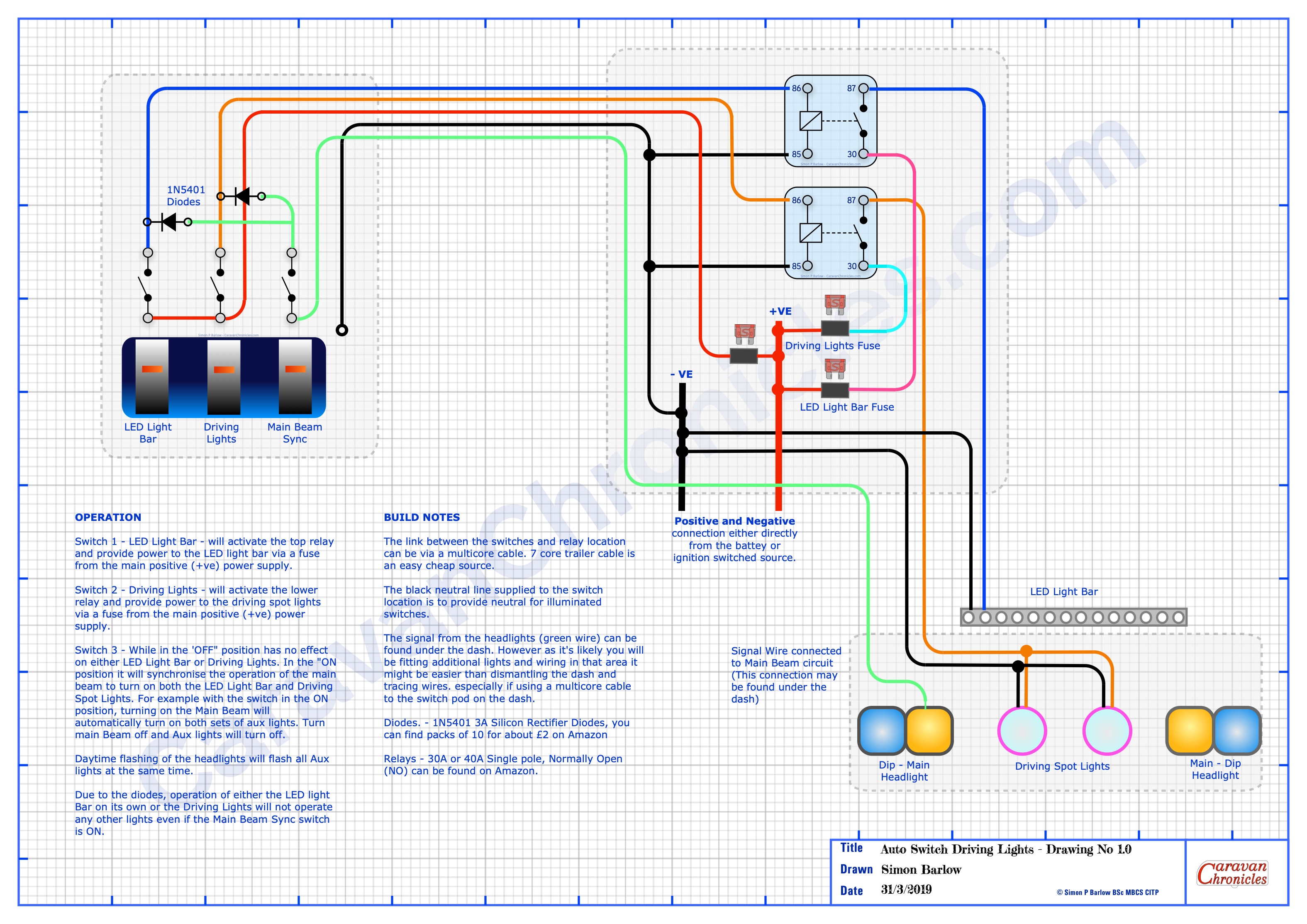
“How can I get my LED light bar and spotlights to come on when I use my main beam switch but I want to disable them when on the highway?”
Link to A3 PDF – Auto Switch Driving Lights
The questions were from a number of 4 x 4 Off Road enthusiasts and Overland vehicle people. Simplest way I could come up with was using a couple of diodes (details on the drawing) Three switches… one for LED Light Bar, One for Driving Lights and one that allows you to sync the LED Light Bar and Driving Lights to the operation of the main beam in the vehicle. Flash the main beam and with the Sink Switch ON… all the lights will flash. Note… this may be illegal in some countries, so having the option to turn off the facility when on the roads ‘should’ keep you within the law…. don’t quote me on it!!!
Question 2
“Whats the best layout for connecting a solar controller / inverter / isolation switch to my battery bank?”

Link to A3 PDF – Overlander Wiring Diagram – 01
The best schematic I could come up with that is flexible for most situations. I’ve put a few notes on the drawing. The various components I’ve drawn generically…. all can be found at your preferred supplier.
Question 3
“What’s the basic layout of the vehicle fridge and leisure battery charing circuit?

Link to A3 PDF – Basic 13 Pin Power Loom 1
This I think has come from a few on-line discussions relating to poor performance of the fridge and leisure battery charing in older 4 x 4 vehicles. I was receiving for a while a number of questions related to upgrading older installations. I also receive a number of emails asking how to add the facility of fridge and leisure battery charging to older vehicles and upgrade the 7 pin tow socket or old military lights socket.
You can download the PDF’s and are free to use for personal use. If you post them on other forums I’d appreciate a link back to this page and/or an acknowledgement.
I’d appreciate any feed back in the comments below.
- Related posts you may like…
- A Request…
- The problem with information from the internet…
- Euro 6 Engines, Smart Alternators and Your Leisure Battery…
- For Anyone Restoring A Vintage Caravan…
- Overland Vehicle Electrics and Other Stuff…
- A Quick Fault Finding Tip…
- Something For Your Toolbox…
- Getting All Charged Up – Update 2…
- Is A Euro 6 Engine Killing Your Leisure Battery?…
- Getting All Charged Up – Update
- Getting All Charged Up – Part 3 “The Install”…
- Getting All Charged Up – Part 2…
- Getting All Charged Up – Part 1…
- Smart Alternators: how they affect Caravans and Motorhomes….

Grounding!
Thank you for these diagrams, most helpful. I am specifically looking at improving my overland rig to exactly what you describe, running very modest accessories.
One thing I would like to clarify is “grounding” (want for a better term) to the vehicle chassis / body. Most manufacturers, such as Victron, make clear in their wiring diagrams for components that battery neutral is grounded to bare metal (effectively infinite 0resistance). Some diagrams I have seen show all neutral bus bars “grounded” too. I note your comment in the overlander diagram that says “NEVER use the vehicle body or framework as a neutral return path.”
My question is: What is the correct thing to do (ground battery neutral, ground all neutral, don’t ground anything) and why? Why should you never use the body?
Many thanks in advance!
On most vehicles now a greater proportion of the bodywork is bonded using glue to each other and any chassis crush components. Some manufacturers ground these panels with a short beaded strap… mainly light panels or panes using electrical elements of the vehicle… such as microswitch to check if your fuel flap is still open.
These ‘bonding’ straps are only designed to take a few amps for the circuit that may be attached. I have seen a panel on a van conversion burn all the pain on the exterior as the current from th small inverter heated up the panel where it bins to an adjacent section of bodywork.
The other thing is copper cables are a known quantity… the steel and aluminium components of body work are not. They certainly have a higher resistance than copper when conducting electricity… especially at higher currents.
Having some electrical aviation knowledge also tells me that there is not a plane flying that uses any part of the airframe structure or skin as an electrical conductor, which given the weight of wiring in a modern aircraft makes you think why not use the airframe as the neutral,,,, you could save 100’s of kg in wiring. The simple fact is vehicle makers cheap out on wiring and use the body as a return path.
Ground all your circuits to a common bus bar grounding point…. then run a wire back to the battery neutral to ground the components rather than to any part of the chassis. It will make fault finding easier, adding additional circuits easier and avoid potential problems in the future.
Thank you, this is helpful. It is certainly what I have done in my initial set up – but I am about to add a DC-DC charger off the starter battery (on a smart alternator) + a 2000W inverter. Victron show on their manuals that the alternator, starter battery, leisure battery and DC-DC converter sharing a common grounding. Lots of online installation guides and some of the ’12Volt off-grid kit building’ websites also assert it must be ground to body.
To complicate matters, my VW Amarok starter battery also says do not use neutral as a grounding (and seems to be grounded to chassis). It is all a bit confusing! What should I do in this instance?
Here’s the Victron manual https://www.victronenergy.com/media/pg/Orion-Tr_Smart_DC-DC_Charger_-_Non-Isolated/en/installation.html (maybe I am misinterpreting). I will probably go for the isolated variant but diagram the same.
BW
On our Amarok I installed a grounding bus bar just below the battery and connected this to the battery grounding terminal on the chassis rail. I also installed a new grounding strap between the engine and the ground bus bar terminal strip. The main battery is grounded to the bus bar and not the chassis. This has done a couple of things…. the original VW earth strap between the engine and chassis is known to corrode and results in cab bus errors from sensors not having a goos quality ground. It also allows me to connect a 50 Amp Anderson connector to allow us to connect directly to our 5th Wheel Caravan. The warnings about connecting to the earth terminal the battery are due to the sensor on the terminal that reports the battery state of charge, charge rate and discharge rate to the vehicle ECU. By installing a ground buss bar the vehicle will detect anything you connect and assess its load on the battery.
For DC to DC chargers I would always recommend running a separate neutral from the vehicle starter battery to the charger. This will give you a vehicle chassis ground and provide a good current path to your DC to DC charger.
A couple of years ago I did some testing on a number of DC to DC chargers and found that by running a separate earth from the charger to the vehicle battery I could just about get the claimed charging rates for the chargers tested….. by using the body work/ chassis I was always a few amps shy on the output… from memory it was about 10% drop in output.
Remember the alternator is grounded to the engine, so if the engine bonding strap is compromised the alternator will not achieve its rated output…. hence why I installed a separate bonding strap.
Also the Amarok has re-gen braking… normally it only charges the vehicle battery to 80% then the ECU shuts off the alternator to save fuel. When you brake it turns on the alternator to max (by upping the field voltage) and during braking the alternator dumps a massive amount of energy into the battery… so that when you set off again the ECU doesn’t turn the alternator on until the battery capacity drops below 80%. This is why you should only install AGM starter batteries in the Amarok.
Hi. I’m really hoping that you can help me.
I need advice on cable mm2.
A quick summary of my solar panel system. 450w panel, 60a mppt controller and a 40a dc to dc charger( I’m using 16mm2 cable)two 240ah agm 12v batteries that intern supply a 3000w/9000w inverter. Originally I intended to use 70mm2 cable to supply the inverter as both batteries would be within 0.5m of inverter. But due to space I now have to have one battery 2.5m meters away from the inverter. So now I’m totally out of my depth about selecting the correct mm2 cable to (A) connect the batteries together in parallel and the inverter. Any advice would be greatly appreciated.
Nigel
The rule is size the cable for the furthest battery… so do the volt drop calculation as thought BOTH batteries will be 2.5m from the inverter. That will give you the correct size and use that to cable both batteries to the inverter.
It’s better to be oversize not eh closer battery rather than undersize on the furthest battery.
Additionally, it will be easier ordaining terminals, heat shrink and you can probably reduce the amount of ‘spare’ cable you would need in two sizes over what you would need in one size.
Thanks for the information. Now I can order the cable without worrying if I’ve got it wrong.
Regards
Nigel.
Sorry to be a pain but, what is the best way to connect the batteries to the inverter. Normally I’d take a positive from one battery and the negative from the other.
Spot on…. if you draw it out on a bit of paper, you will see that you actually need three cables between the batteries….. pos and neg connecting them together, then an extra neg to feed your inverter. I alway opt for the the extra cable to be neg as it reduces the cable actually carrying pos to one between the two batteries.
I try to keep the pos cables as short as I can.
Excellent advice. I would never have thought about having three cables. Now I can buy the correct size and not waste time and money on the incorrect cables.
Pingback: Vehicle Wiring Projects… Some Thoughts. | Caravan Chronicles
Pingback: Something For Your Toolbox… | Caravan Chronicles
Pingback: For Anyone Restoring A Vintage Caravan… | Caravan Chronicles
Pingback: Euro 6 Engines, Smart Alternators and Your Leisure Battery… | Caravan Chronicles
Pingback: The problem with information from the internet… | Caravan Chronicles
Thank you Simon
Great diagrams
Very interesting post as we seem to have a constant issue with our fridge working on 12v while travelling. There is an expensive solution, but not willing to fork out that sort of cash for the odd occasion that we will require the fridge working on 12v. When overlanding one of the last things you need to happen is for your battery to get fried. No spares shop around the corner. In the past I have got a lot of useful information from https://www.4x4community.co.za/forum/ as they have experienced many issues and have found ways to overcome these issues.
Ian
I find it better to run my fridge on 240v (Australia) via an inverter.
Hi reading this, I have had a good friend build me a clever unit that turns a small compressor fridge into camping fridge, it’s a 240v relay with snubbers, that allow a 300 watt inverter run fridge until plug into site then auto switches to mains and allows the charger to replenished the leisure batteries. We are going to also install a 80amp old style Lucas alternator directly to charging circuit to bypass all the can bus nonesence
Pingback: Overland Vehicle Electrics and Other Stuff… | For Holidays and Staycations in the UK