
I’ve written this page to help answer some of the many questions I have been asked after the original article “How To: Connect two batteries in parallel” was published. It covers some of the practical considerations to installing battery banks in caravans, motorhomes and vehicles.
A word of caution: Leisure batteries store an incredible amount of energy and if you short them out or connect them incorrectly then this energy can be released almost instantaneously with disastrous consequences. If you have any doubts about what you are doing then seek qualified professional help.
Connecting more than one additional battery
In the first part we went through the correct way to connect an additional battery…

A number of people asked for a drawing to show the correct way that more than one additional battery could be connected so that the voltage drops across all the batteries would be equalised and the batteries remained balanced in the bank.

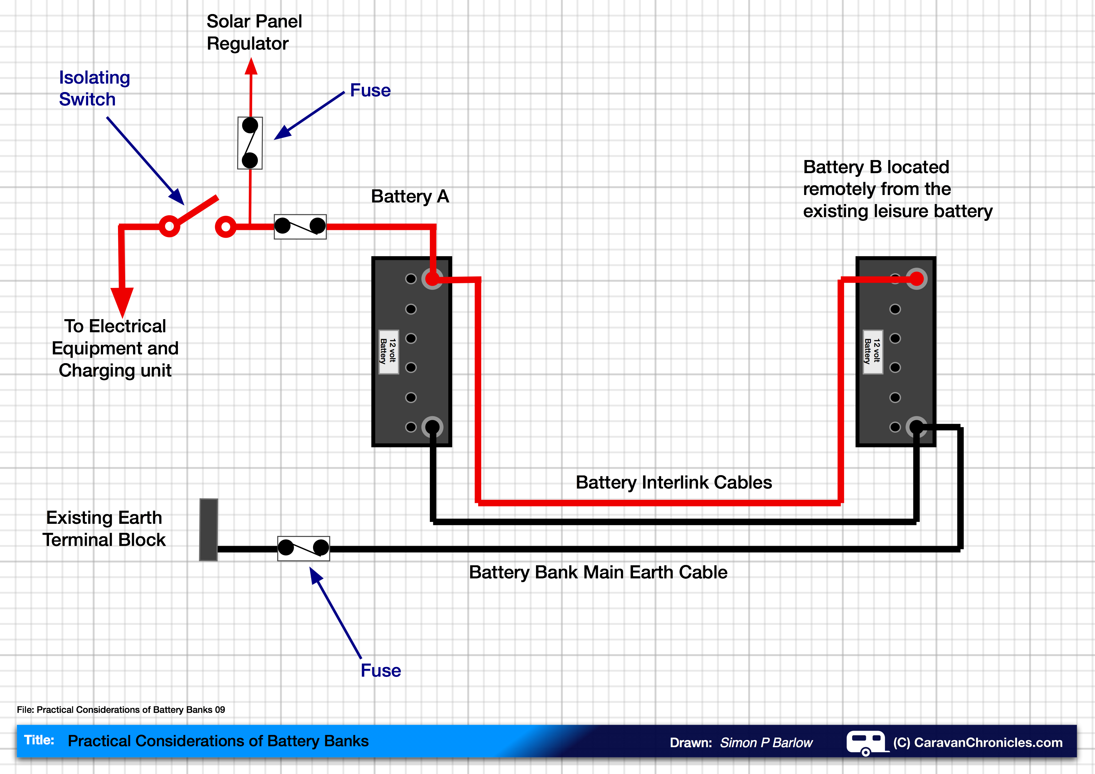
Remote Battery Location
The next question often asked is how to connect a second battery if it can’t be located next to the original battery. Installations in some motorhomes and campervans only have space for one and the second battery needed to be located remotely at the rear of the vehicle or on the opposite side.
REMEMBER: When installing a second battery in a remote location it must be sealed off from the interior of the vehicle and the battery compartment vented external to the vehicle. There are battery boxes available that do this.
The existing set up will have all the live and neutral cables terminated near the existing leisure battery and it would take some effort to have to relocate all the earths for each individual circuit to the second battery location, there is a simple way of achieving it.
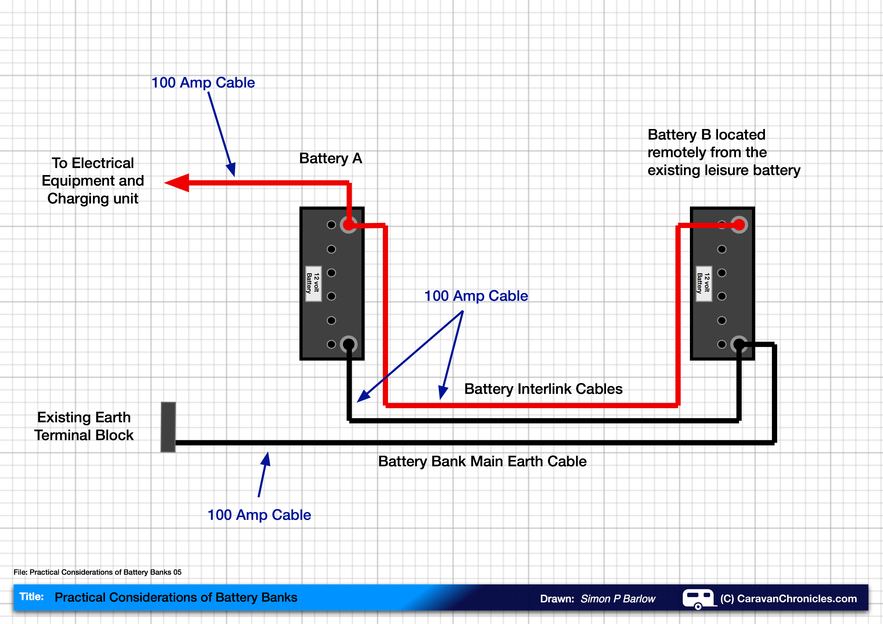
For the remote location, an additional cable is required. In the first drawing at the top of the page it shows the live cable coming from the second battery which is fine if the two batteries are adjacent. However with a remote battery this would require running two live cables through the vehicle and common sense tells us that it would be better if we only had to run one live cable. (drawing below)

In the drawing (above) it can be seen that now we have three cables running to the remote battery. Two battery interlink cables and a main earth cable. This has now reduced the amount of live cables running through the vehicle and allowed the original earth terminal block that the auxiliary services use.
Cable size
A number of people asked about the sizes of the cables required to link the batteries together and raised the question could the cables linking the two batteries be smaller than the actual cables connecting the battery bank to the equipment. Their thought being as each battery was supplying 50% of the current the size could be reduced.

In the drawing above the battery bank is wired using 100 Amp cable (I’m rating the cable by current rather than cross-sectional area as it’s a bit easier to follow) From the battery bank there is a 100 Amp positive and a 100 Amp negative cable. The battery interlink cables are sized at 50 Amps as that is the current between the two. We’ll ignore any fuses for the moment – more about that shortly.
Well OK it could work, however if you were using an 1200 watt inverter that put a 100 Amp load on the battery bank and a cell in battery A failed so the battery effectively had little or no output, then Battery B would continue to supply the 100 Amp load put on it by the inverter… and the interlink cables are only rated for 50 Amps, therefore something’s going to get hot!
If you are going to demand 100 Amps from your battery bank… then use 100 Amp cable throughout the installation.
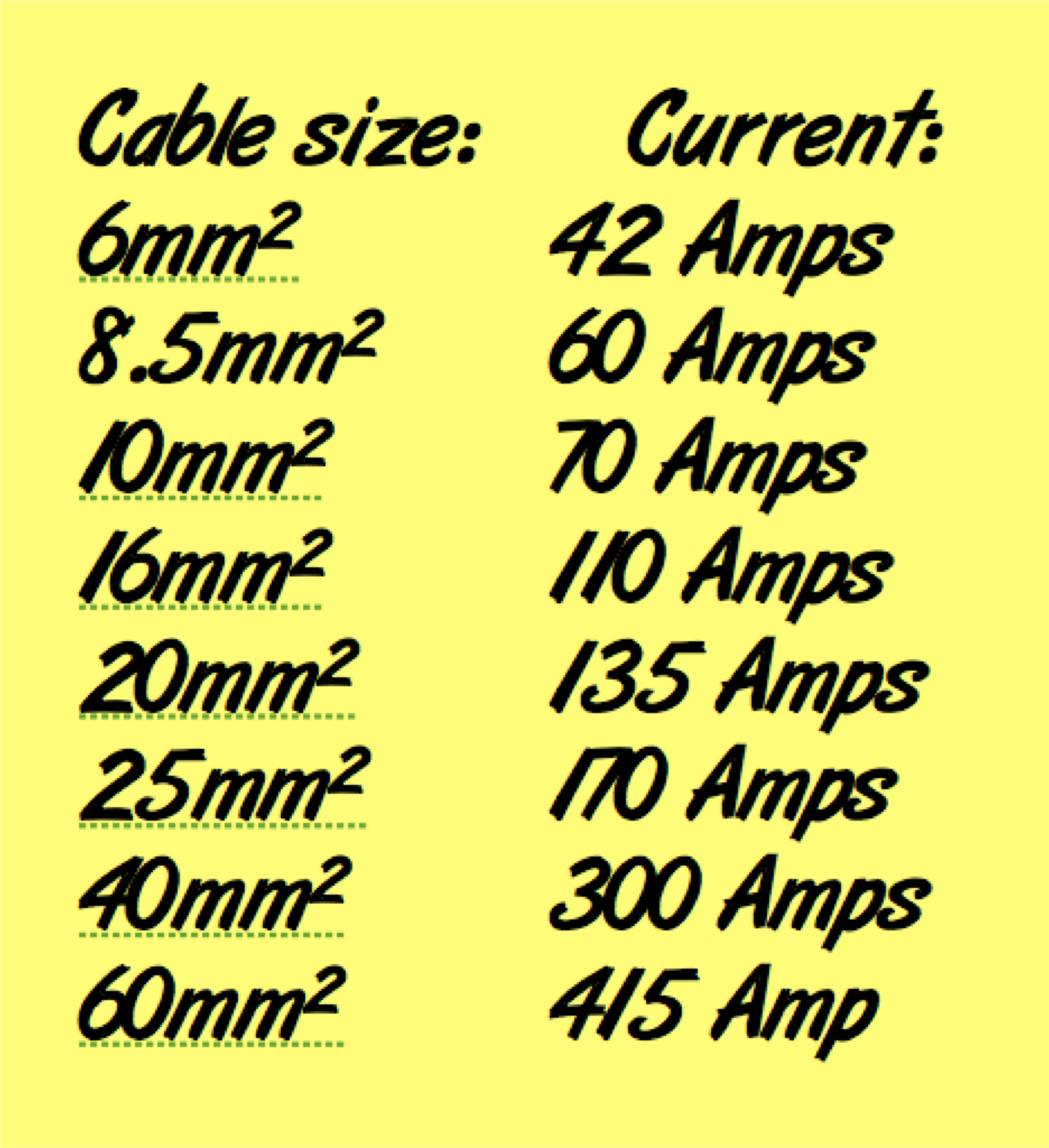
Calculate the maximum load you will ever put on your battery bank and size the cables to that load. Before finally selecting and settling on a cable size though it’s worth reading Understanding Cable and Cable Sizes as there might be a bit more involved.
Here is a rough guide to current capacity for good quality cable:-
Where to install fuses?
Convention is fuses are installed in the positive cable coming from the battery bank.
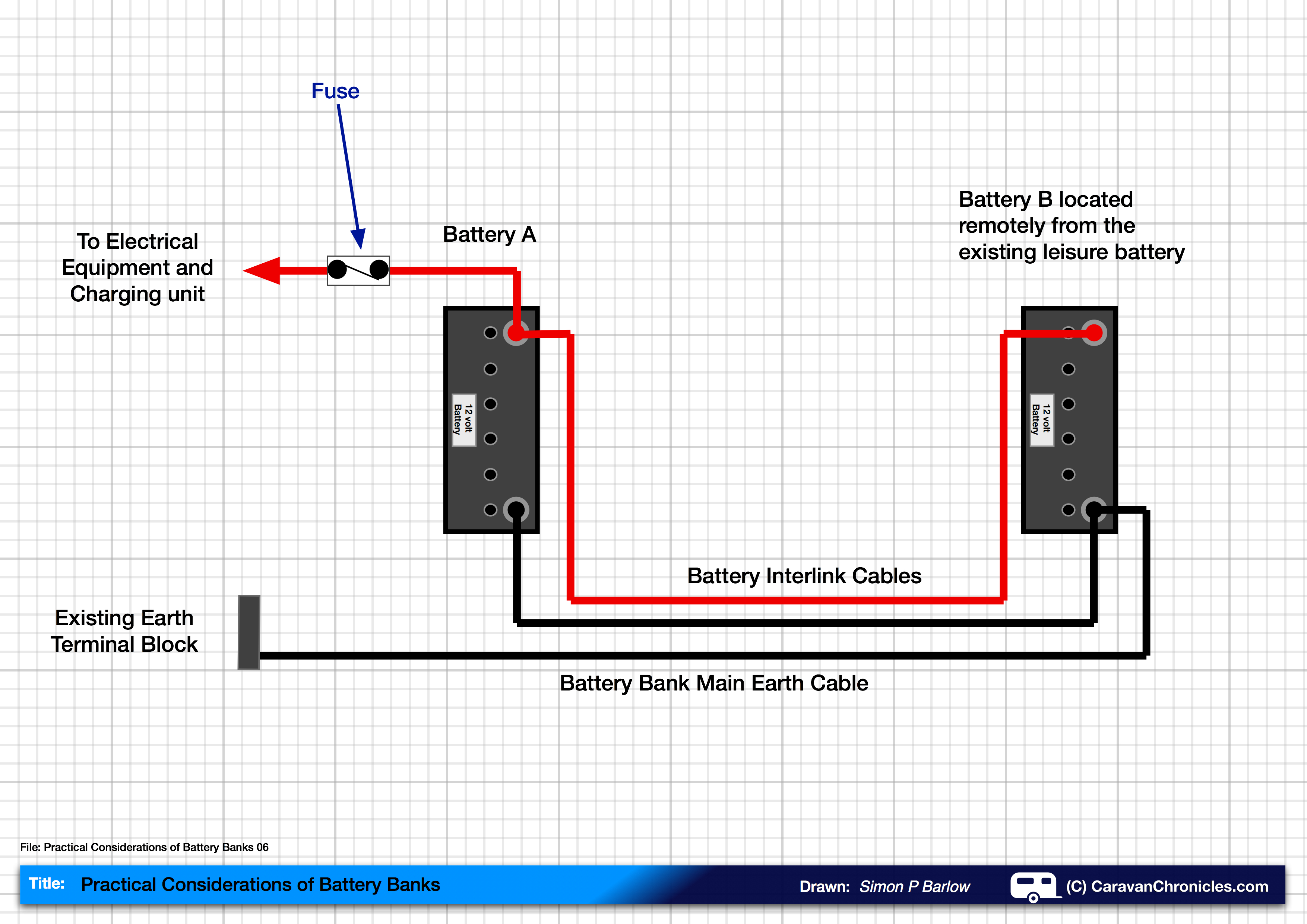
However if there is a short in the positive battery interlink cable to ground because of the longer cable run through the vehicle due to damage or chafing, then the main fuse will not protect anything in this event.
The sensible thing would be to install a fuse on the interlink cable as well… but at which end? The conventional location is as close to the battery as possible… but there are two batteries and if the short is at mid-point one battery will still be connected.
So we have to install fuses close to each battery. Now the problem comes with what size fuse.

Fuses are there to protect cables from overload and possible overheating and the general rule is the fuse rating should be equivalent to the current rating of the cable or lower.
Lets assume we have completed the installation in cable rated to 100 Amps. So we install fuses rated at 100 Amps at the points in the drawing above. Disaster strikes and we get a partial or intermittent short somewhere along our positive battery interlink cable to ground. Now at the point of the short, potentially 200 Amps could flow – 100 Amps from each battery and not blow the fuses. With 200 Amps we could be welding bits of metal together. Because it’s in the middle of the battery bank there also might not be any indication that there is a problem…… until it’s too late!
Is there a solution?
Well this is what I came up with:-
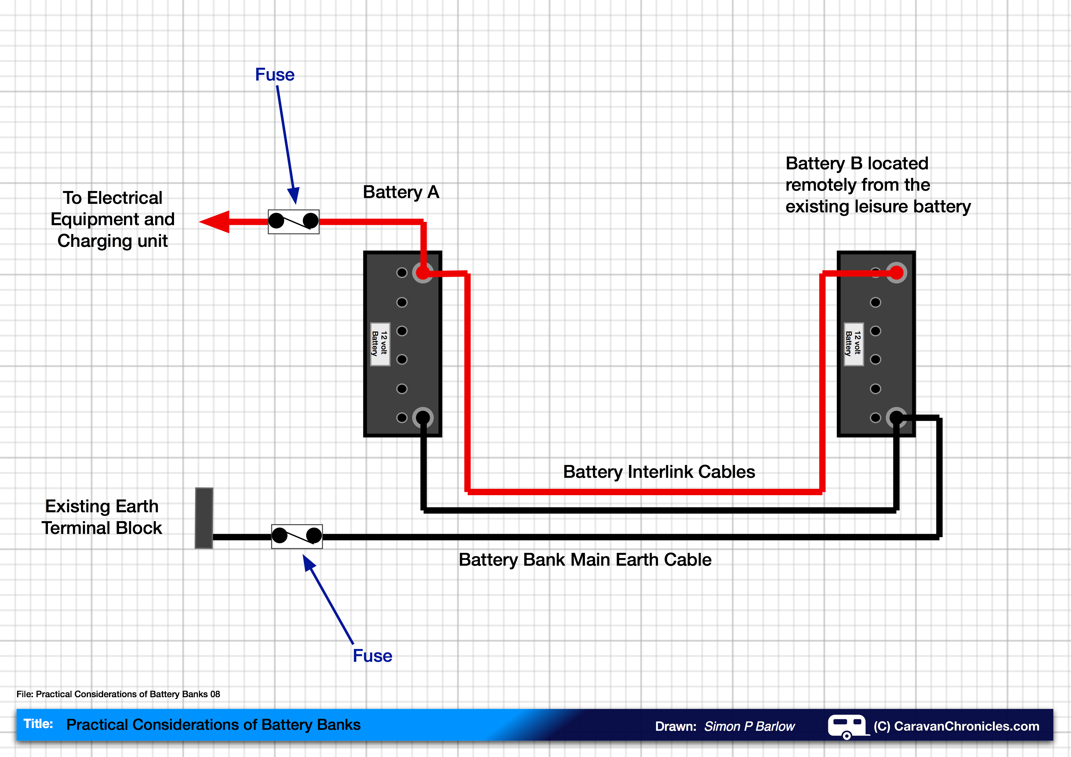
Installing a second fuse in the main neutral earth cable would protect the battery bank from any potential shorts down to the vehicle earth from the battery interlink cable. If there were a short the current would blow the fuse in the battery bank main earth cable.
IMPORTANT NOTE: There must be no connection between the battery bank and vehicle or other earths/grounds other than at the main earth terminal block for this to work!
For clarity I have removed the fuses from the drawing that were in the positive battery interlink cable. In practice it would be prudent to leave one in to protect against inadvertently shorting out while removing or installing batteries.
Installing a battery bank isolation switch
Another question that kept cropping up was based around “How can I install a battery isolator but still let the solar panels charge the batteries even when they are turned off?”
As long as the solar panel regulator is connected to the battery side of the isolator switch, then even if the isolator switch is open (the battery bank turned off) then the solar panel regulator will still be able to charge the battery bank.
Although the isolator and cable might be rated for 100 Amps and the battery bank fuse be 100 Amps, if you are connecting the solar panel isolator with 10 Amp rated cable, then the fuse between the battery bank and regulator needs to be sized accordingly… i.e 10 Amps (remember the fuse is there to protect the cable and must never be rated higher than the cable it is protecting)
If you have found this article useful, please like, comment, subscribe.
Further Reading:
Understanding Cable and Cable Sizes – When undertaking an electrical project for your caravan or motorhome one key consideration is what type and size of cable to use. Selecting a cable that is too small for the task and you might risk melting the cable insulation or damaging equipment due to voltage drop.
UPDATE – More info can be found on my blog here…. Overland Vehicle Electrics and Other Stuff…
Copyright © 2011 – 2019 Simon P Barlow – All rights reserved

Hello. I have a Citroen Berlingo campervan and I’m currently running a 2kw pure sinewave power inverter with 1 110amp leisure battery and I want to connect a 2nd leisure battery but the only problem is that one battery is in the passenger rear foot well area and the 2nd battery will have to be on the drivers side behind the drivers seat under my sofa. The cables to the 2nd leisure battery will be about 50 inches long and the cables on the 1st battery are about half the length. I’ve heard that having different lengths of cable will reduce power to that battery if it is further away so I’m worried I won’t get an equal 50/50 power drain. Thank you.
Brilliant information,and simplified instructions thank you!
My understanding is that if there is a battery short, then more than just 100A will flow from the battery. It will basically vaporize the device sustaining the short with thousands of amps of current. Typically we see fuses that have an interrupt current capacity, i.e., their capability of how much current they can break and how quickly.
My background is as an Electrical Engineer for renewable energy systems, but now that I’m doing a van fitout, I can’t actually find the fault current (short circuit current) information on the battery data sheets, and nor can I find the maximum interrupt current of the fuses…
Basically I’m wondering is this danger being accounted for?
Hi Sean
You can work out the theoretical max current of any battery by measuring it’s internal resistance (I can’t remember off hand if you use forward resistance.. I think it is) and calculate the energy in Joules.
In reality the stored energy at short will dissipate through the short quite quickly at max current. A typical 120Ah battery will only sustain max current for a very short period of time. The issue however is battery banks. As these have the potential to store a lot of energy, the limit has to be enforced by fusing and design. If you have a large battery bank that is capable of a sustained output of say 500 A over a period of time but are only using a 1500 W inverter as the biggest device, then obviously the main battery bank fuse needs only to be rated for what this device can draw.
You design a battery system based on either one of two conditions. You store a set amount of energy for either a quick discharge to plug a gap between the main power going off and a generator kicking in OR as in motorhomes and camper vans to store an amount of energy to be given back over a longer period of time while off grid. Although you may store the same amount of energy the design of the two battery systems is vastly different.
Until recently there was not really much consideration given to 12 volt lead acid batteries in vehicles. The issue of a dead short in an accident was not that serious as the amount of energy stored was relatively small. That all changed with electric vehicles. If you look at the amount of energy stored in a Tesla battery for example. that is massive in comparison. Fire rescue services are now having to develop special procedures for dealing with EV’s in accidents.
You are quite right to be cautious. Having blown a battery up ( 12 volt 60Ah type) as a kid by doing something stupid. Since then, I have always had a healthy respect for the humble 12 volt lead acid battery.
Hi Simon, this is a great article, and thanks so much for posting it. I have 5 x 40aH batteries connected in parallel, just as you suggested here, but I was advised to connect the charging input wiring on the opposing terminals, (not the same terminals supplying power to the RV’s devices). What’s your opinion on that? Kind regards, David
Hi David
Honestly I can’t see a reason why you couldn’t connect on the opposing terminals. The OCD in me though would suggest keeping all the connections from the load side and charging side should be all on one pair of terminals would be neater and also require one less fuse.
Hi,
I just bought my van that came with a whole system but I want to connect one more battery. The current one is just 3 months old so I bought the same size and brand to connect parallel.
I have two 235w solar panels connecting into a solar charge controller. From the controller its connected to the battery +, – and to a battery voltage gauge. From the voltage gauge I have 3 outputs to aux; lights and pump. Aux has a 20a fuse, light 10a fuse and pum 7.5a fuse. Between the battery and the battery voltage gauge panel I have a 30a fuse. From the battery I have a 140 amp split charger. Also from the battery I’m connected to the 1000w inverter.
Questions:
When I connected the second battery do I need to change anything in the system?
Should I put a fuse elsewhere?
Should I buy a larger power inverter for the system?
Hi
The basic set up you have with an extra battery will be fine. It will double your storage capacity and ability to stay off grid. As long as the second battery is located next tot he original battery and the connection leads are less than 50 cm in length then you don’t need to add an additional fuse for the second battery.
A 1000w inverter will cover you for most of the small appliance needs (laptop charging, TV, camera battery chargers etc), you would only need to go to a 2000w inverter if you had for example a large hairdryer.
Have a look at what appliances you want to run and check the wattage load given in the manual on on the info sticker on the appliance so you don’t exceed 1000 w.
Thank you. It made a lot of sense.
Many Thanks
Thank you for your reply. Just to clarify to make sure I understand correctly, I should use the peak surge for my calculations, which going by my inverter specs is 6000w for a maximum of 2 seconds, and 4500w for a maximum of 10 seconds and a continuous rating of 3000w. Is it also normal practise to to install a fuse 25% above your max current draw? , which in turn also increases your cable size to be above the fuse rating as well as length and voltage drop.
Many Thanks
Cable should be sized on peak draw and the fuse sized to match the cable. So if it’s 220 A peak surge, then 250A cable with a 250A fuse. Fuse to the cable size… the fuse is there to protect the cable not the equipment.
In practice it is highly unlikely that the inverter running at 6000W for 2 seconds would blow a fuse protecting cable sized for 4500W running capacity.
Hi Simon
This is my third attempted to ask a question, for whatever reason they are not getting posted, apologies if they are and now you have 3 identical questions from me.
I’ve looked at your old articles but couldn’t find anything on inverters, if you do have one and I missed it could you point me in the right direction.
My question is regarding cable sizes for inverters. I have 3000w Continuous which peaks at 6000w. Should I size my cables based on 3000w/250 amps or 6000w/500 amps (12v system) the cables supplied are 16mm2 which is only good for 110amps but they supply 4, 2 pairs so I assume two together covers 220 amps? (There is a pair positive and a pair of negative terminals on the inverter for input) I also suspect that each cable should cover the total amps I could be using, and my battery strings should also be updated to cover the max amps also regardless of how many batteries are in the bank.
Hope this makes sense.
Thank you.
Hi
All the comments go through a moderation process and some times I get a bit behind. I did write an article on inverters… https://caravanchronicles.com/guides/understanding-inverters/ and there is a part two to this article.
I’ve always found that any cables supplied with inverters tend to be undersized and don’t have the best termination crimped on… and sometimes the crimping can be a bit choppy and always advise to steer clear of them TBH.
You cannot under any circumstances ‘double up’ on cables…. it causes all sorts of potential problems including fusing. You need to get the correct size cables for the total max current rating and must take into account the length of cable. Have a look at https://caravanchronicles.com/guides/understanding-cable-and-cable-sizes/
If you look at any cable manufacturer, they will show a cable size chart based on current rating and cable length. Ince you get above 100 Amps you need plan carefully the cable route to try and minimise loss and keep the cables as short as possible.
Great and helpful article, thanks. I have ordered 2 AGM leisure batteries. However my starter battery is NOT AGM. Do I also need to change the starter battery to AGM or is it ok for the starter battery to be a different chemistry than the leisure batteries ? thanks in advance
Hi John
As your starter battery is not part of the ‘battery bank’ then yes it can be a different chemistry.
Bit late to the party on this one, but thanks for such fantastic articles (and here’s hoping you’re still curating to reply to this! 😉 ).
I’m currently wiring up my van, and unfortunate geometry means I’ll have four 12v batteries in two pairs, about 2 metres apart. I need to run these in parallel to maintain 12v, but can’t work out if it’s possible due to the voltage drop issues discussed in the previous article (i.e. Battery 1 will have a much shorter path to the device than Battery 3 has to the ground, even if the device is wired to the positive of 1 and the negative of 4).
Likewise I’m not sure what the effect of having ‘asymmetrical’ wiring would be – Inverter etc are likely to be less than 50cm from 1 and 2, but 2m from 3 and 4.
And to complete the hat-trick, how does the distance between parallel batteries affect voltage drop/wire thickness calculations? The positive -> device (50cm) and device -> negative (2m) means I’m looking at 2.5m round trip distance, but should I also be including the 2m between the batteries (or even 4m between the batteries for two wires??)?
Hi
I have just published a blog post that has an information sheet about wire size for various loads and length of cable that might answer your questions…. https://wordpress.com/post/caravanchronicles.com/6670
Ah, I think my comment got lost in WordPress disconnects! I said many thanks for another great and informative article. I’ve now printed out a couple of the reference sheets and all 🙂
I’m still stuck though on how the wire length should be calculated. Three options as I see it:
1) Length from the positive terminal of 1 to device and back to the negative terminal of 4.
2) Length from the positive terminal of 1 to device, back to the negative terminal of 4, and from positive of 4 to 3, 3 to 2, and 2 to 1.
3) Length from the positive terminal of 1 to device, back to the negative terminal of 4, and from positive of 4 to 3, 3 to 2, and 2 to 1, AND from negative of 4 to 3, 3 to 2, and 2 to 1…
Can you shed any light?
Thanks again!
Must be missing something here….
Quote:
“I’m still stuck though on how the wire length should be calculated.”
Normally I’d use a tape measure.
Hahaha I mean of my options which is the correct ‘total length’ – is it just the wire from positive to device to negative, or does it include the wire connecting the batteries (and if including this wire, is it ALL of this wire – connecting negative and positive sets of terminals – or just one set – all the positives, for example)?
When calculating drop for battery bank cabling, it’s the length of all the cable connecting the battery positives to the main distribution terminal and the length of all the cable connecting the battery negatives to the main negative terminal.
Technically (theoretically) you should work out the drop on each length of cable then work out the drop within the bank, but working on the two totals is close enough.
Perfect, thanks so much for the help! 🙂
Hi Simon
These articles have been really helpful as I’m about to fit two batteries into my van conversion. I do have one question regarding the sizing of the interconnecting cables between the two batteries though. I’m wondering does the size need to account for both charging and load? For example say I am parked up on hook up and charging off of both solar at 20 amps and hook-up via a smart charger at 25 amps whilst simultaneously running some equipment (fridge, lights, etc) that totals say 60 amps (these figures are for the sake of argument and not specifically related to my build) would the cable between the two batteries need to be able to handle the overall total of 105 amps or just the 60 amps since this is the biggest figure between charging and load? I ask this as lots of places say size based on the cable coming out of the positive, but only seem to discuss this in terms of the items you are running off of the batteries and not the charge you are putting in.
Cheers
Josh
Hi Josh
What usually happens is if you’re charging at 45 amps (20 +25) with a load of 60 amps due to the fact the charger is at a higher voltage you have 45 going ‘in’ and 60 coming ‘out’…. what it really means is the charger will supply a lot of the current due to being at a higher voltage and the battery only supply part of this… say 15 amps.
Although in theory this is what happens, there are many things that can ‘distort’ the maths above… the smart charger voltage might drop as the “load” it sees of battery and running equipment will seem too much for the charger and it is not capable of providing enough current (or is limited electronically) will reduce its output voltage accordingly and the battery will take up the slack.
You have to look at it as a net effect on the battery bank rather than an in and out. If you are charging, the battery will never be supplying all the current to your equipment. If the maximum current draw on the battery bank with everything turned on and not charging, is 60 amps, then cable rated at 60 amps (I’d personally go next size up for future capacity) is fine.
This is a simplistic view of what goes on and is dependant on how it is connected and the charger. Some chargers for example have connections for load and connections for battery so they can manage the relationship between charging, load supply and battery life.
Hi. Great articles, thanks for all the thorough insights, helped me a lot 🙂
I do have an issue however:
I just bought 2 new 12v 120ah leisure batteries, hooked up in paralell and connected via a dual sensing vsr to my van battery.
The new batteries are holding a charge of 12.9v as they are new and very good.
The vsr cuts in at 13.7V or higher and cuts out at 12.8V or lower.
So, as its a dual sensing vsr, my new leisure batteries continue charging the van battery until they fall to 12.8v but id prefer not to drain the new leisure batteries down to this as id like them to hold as much as they can obviously.
What are your thoughts on this?
Thanks.
Hi
I’m not sure what you are trying to do… are you using your leisure batteries to charge your van battery?
hi, very good article, thanks for it.. just about to connect up my battery bank (2x battery) for the first time ever.. you said “There must be no connection between the battery bank and vehicle or other earths/grounds other than at the main earth terminal block for this to work!” – Is this mean I should connect the starter battery’s negative to the earth terminal block? or where should I connect the first leisure battery’s negative?? I’ll use VSR split charger..
It’s always better to use a single point of earth for the batteries so as not to rely on the vehicle bodywork as a current path.
Hi, just read it above always try and keep both cables the same length. Missed that bit first time.
Hi, in your diagram you have taken the positive wire from battery +post A on a round about route to battery +post B rather than straight across. Is this to try and keep the live cable the same length as the Earth cable.
Hi Steve
I drew it that way as it’s usually the routing that people may use if they can’t co-locate two batteries in the same place. It wasn’t drawn intentionally to keep the cables at a similar length.
Keeping them similar lengths is not as important as keeping them as short as possible.
Question for you sir, my diagram would be more like the one that’s the 3rd one Up from here with the 3 fuses on the positive. My question is could I run off of battery B take off and hit my two amps (1) 4000 and the other (1) 500 amps ? Reason is battery B is 15 ft. closer to my amps, and still have battery A feeding all of the vehicle electrical, but wired in that configuration.
Sorry Simon let me confirm a couple of things I forgot to let you know about this issue above. Battery A is a 9 month old Napa standard lead battery the CCA is 850, Battery B is brand new Bosch Platinum AGM battery CCA is 750, I have run between the two batteries, both positive and negative 1/0 gauge. Your opinion is appreciated, and valued, hopefully you haven’t commented on this already I read through all of the ones I found and didn’t see a scenario like this, so hopefully not wasting your time. HAPPY THANKSGIVING
Hi Joel
Sorry for the late reply.
As I understand it, one battery is a wet lead acid type and the other is a AGM battery. If this is correct I would not recommend connecting these two in a bank. The charging and discharging characteristics are completely different and you will probably have issues charging them as a pair.
Thanks for really helpful info. Previous owner had connected two batteries wrongly, which I’ve now corrected as per your diagrams. Which terminals should I connect a Ctek smart charger to: + & – on one battery or + on one battery and – on the other?
Hi Ron
I would connect your Ctek charger +ve to one battery and -ve to the other, this way any volt drop will only be across the interlink cable.
Hi there, Great Read. I am adding a new 29 group battery underneath to the frame in the back of my van to increase my power reserve. It is much larger than my starting battery. I have a 130 amp alternator. I will be using an 80amp continuous duty/150 amp surge isolator solenoid for charging. (Assuming everything is wired and fused correctly,) When the engine is off and the “house” Battery gets drained. When I go to start the engine there will be an equalization and i am wondering how the voltage regulator in the alternator is going to respond to this process as well as how it will respond to the to different types of batteries when charging, Thank you for your thoughts.
Hi John
The solenoid should not operate until the alternator is providing an output, therefore there should not be an issue with the batteries trying to equalise. The alternator will just provide a charging voltage for the type of battery that was specified for the vehicle, if you have a different chemistry house battery (AGMI, AGMII, GEL,LiPo etc) it would be better to install a DC to DC charger that can accommodate the house battery chemistry type.
Hey mate, really loving your write ups! Very intuitive. You made mention of doing a post about wiring two batteries in parallel to power a winch, I can’t seem to find that post or is it not done yet?
Look forward to hearing from you.
Alex.
Hi Alex
I changed my tow vehicle last year and I’m not sure if I will be installing a winch on the new one.
Ah that is fair enough. Cheers fpr your prompt response. Would placing a winch in the circuit like you have shown in this post do anything majorly wrong?
Cheers
Hi Alex
The main issue is protecting your starter battery, I’d go for running the winch off a second battery (or pair) that is not connected to the starter battery and invest in a DC to DC charger so that when the engine is running once the starter battery is topped off, the winch battery gets recharged.
A DC to DC charger is not the same as a split charge system, as a split char system will only put the alternator output into your battery. A DC to DC charger has a smart multi stage charger that will take the battery through bulk, absorption, float and DS stages to make sure you get the best out of it.
The other thing is it will also protect your alternator so you can leave your engine running while operating the winch without fear of causing damage to it.
Hi..I have a new motorhome with a 100watt solar panel that is permanently connected to the leisure battery. However there is no provision for charging the Vehicle battery and I am thinking of the time when it is parked up (including winter storage) with the alarm set. From what I read this can run down the VB in a coup[le of weeks.
have I fitted a 12 socket, fused at 10 amp, near the VB (which is inside) and have made a lead (as suggested on an internet forum ) which can connect the LB and the VB in parallel but I have included a shottky diode (VF=.0.3 volts) in line, in the belief that solar controller cannot “see” the VB and will (my theory) will continue to keep the LB fully charged but also trickle charge the VB at the same time. I have not simply connected them directly in parallel as they are different types of battery. Is this a madcap scheme !?
Hi Robert
Sorry for the delay in replying… I’ve been mulling this over.
I can’t see anything wrong with what you have done. As long as the solar charger output voltage is above the voltage of the LB and VB, then the VB will charge. The only thing I would caution about is forgetting to unplug the lead before you start the engine just in case it has any detrimental affect on the vehicle to leisure battery charing system.
For the future, you might want to look into a MPPT solar charger with dual output. These are designed to do exactly what you are trying to do but being MPPT you will maximise the potential of your panel.
Hi Simon, not sure if you’re still responding to comments in response to this really useful and informative post. I have wired two batteries in parallel as you’ve shown. The positive from battery A runs to the blade fusebox for the appliances and I have the earth/negative coming back from the blade fuse box. My question is – does is matter if I connect this earth/negative from the appliance fusebox to the -ve of Battery A, or should it be connected to the -ve of Battery B? Thanks
Hi
If the +ve is coming from battery A, the -ve should be connected to the -ve post on battery B. This will eliminate any voltage drop losses due to cabling between the batteries for both charging and discharging.
Ok that makes sense. Thanks very much
Hi. All thing being equal, and everything wired as you suggest in a Part 1 and Part 2, where do I connect me charger? Thanks for info, it makes good sense, however do I connect charger + and – to separate battery terminals, and what if I have three batteries?
Hi
Your charger should be connected to the `=ve terminal where you take the feed from the battery pack and the -ve to where the main -ve connection to the battery pack is.
The charger should always be connected to the main connection to and from the battery pack no matter how many batteries there are in the pack.
Simon, what is the ” smart charger ” you mention? Does an ordinary charger not work on lesiure batteries?
Ta, John Cole
Hi John
A smart charger is a multi step charger that first checks the sate of your battery then using a 6 or 8 step process can de-sulphate the cells, condition them and finally charge them then float the cells long term. Here’s a link http://www.ctek.com/gb/en/chargers/MXS%2010
Very interesting read. I do have a question though.
I’m connecting two batteries of the same voltage in parallel:
Battery A has a relatively small capacity (I cant remember the exact number) and is flat.
Battery B has a much higher capacity (110Ah) and is fully charged.
When I connect these together in parallel, the 3A fuse installed between them blows. I have previously just connected these straight together with no fuse and it has ‘worked’ but I wonder what this might be doing to the batteries?
I guess because the potential difference between the batteries initially is relatively high, and the resistance between them is low, that the initial current is high (thus blowing my fuse), but will this damage the smaller capacity batteries in absence of a fuse?
Am I correct in thinking that once the pd between the cells has ‘balanced out’ surely they’ll discharge at an equivalent rate such that the voltage of each cell is maintained? And will just ‘look’ like a single cell of the combined capacity of the lot of them?
They won’t be charged in parallel, but what is the implication of this? To me it feels like this *could* be bad?
I fully accept that they would ideally be both at full voltage before connecting…
Hi Chris
The internal forward resistance of a discharged battery is quite low, so connecting a second battery in parallel that has even only a small voltage difference will result in the batteries trying to equalise quickly, hence the fuse will blow. Ideally the best way to equalise batteries is to connect them to a smart charger individually and let the smart charger do it’s magic and once all the batteries have been through this process, only then attempt to connect them as a bank. Personally I use a C-TEK multi stage smart charger and haven’t had any issues using this method. Once the batteries are connected in a bank, I use the C-TEK again to do one final charging session and from then on use the C-TEK to equalise the bank on a periodic bases even though the bank is discharged/charged by the caravan services. Good batteries are expensive and I try to look after them as best I can. So far my batteries are 5 years old and not (touch wood) showing any signs of ageing.
With regard to connecting batteries of differing Ah ratings, the smaller Ah battery will usually fair less well going through charge/discharge cycles when connected in a bank.
Thanks Simon, excellent info, looking to set up a chalet with off grid electrics and this has been a good introduction into battery ‘set ups’
Thanks Simon – Ideally another new battery to match the existing new one would be good, but that’s another £80, and then I’m left with 2 perfectly good spares. I really don’t want 4 batteries. I will try the 1 year old with the new. Hopefully they will both last several years.
Fascinating article but I have a question no one has asked yet. I have 3 110Ah leisure batteries. One is 6 years old, one is 2 years old and the one is brand new unused. They are all identical Numax XV31MF. Would it be OK to parallel the 2 year old and the new together? I don’t understand why you stated the manufacture date should be the same. All batteries have been maintained with a CTEK charger.
Hi Syd
Basically as soon as a battery is filled with acid at the point of manufacture or by the retailer the ageing process starts. No matter how efficiently an older battery is maintained, it will have aged compared to an younger identical battery. When you pair an older battery to a new battery generally the new battery will age quicker to match the older battery as its the older battery that will dictate the charging regime.
This is a bit of a generalisation though as each manufacturers products behave slightly differently.
Again another thing to note is that even though two supposedly ‘identical’ batteries from the same manufacturer but manufactured one or two years apart carry the same specification and part number, they in all probability will have some differences due to manufacturing changes and material changes made during the intervening time.
Personally if I was setting up a new battery bank, I’d go for matched products. However, if I was just adding to an existing battery bank to extend the capacity, knowing that I may be reducing the life of the new battery slightly by adding it to an existing bank, I’d be OK with that and plan at some point in the future on upgrading the older battery when funds allow and performance drops.
Brilliant article, really helpful.
great read! made my simple application even simpler.
setting up a two battery bank. Thank you.
Hi Simon, Many thanks for your reply I will move the connection across and check with the manufacturer about the dedicated Solar panel input although I cant see one on the control panel of my Trigano T720. Rob
Hi Rob
Sometimes the solar panel input is just a 2 pole connector in the wiring loom. Our Sterling Celebration caravan has one hidden away behind the charger.
Simon
if I install a second battery will I have to move all the negative cables to the second battery?
Hi Mike
The +ve leads should originate from one battery and the -ve leads should originate from the other battery in a two battery set up. It is sometimes easier to move the +ve lead if there are several -ve leads terminating on the original battery.
Simon
I have a 100 watt solar panel and have 2 x100ah identical batteries I have wired up the batteries as the article and all seems ok. I have wired up the solar panels pos and neg tobattery A is that. Correct ? . although there is a regulator on the back of the panel when it appears that when the batteries are fully charged or being overchargedan alarm goes off on the control panel of my motorhome this obviously goes off when I disconnect the panel, do I need another Controller ? Regards Rob
Hi Rob
Really the +ve needs to go on to one battery and the -ve from the regulator needs to go to the other battery to make sure any voltage drop is even between the two batteries.
I would suspect the alarm is the over voltage alarm on the motorhome, although with out knowing the details it’s hard the be certain. I would check the output from the solar panel regulator to make sure it was within it’s specification max voltage. I would also check to see if there are any details listed in the motorhome manual (or with the manufacturer) on the max voltage before the over-voltage alarm is activated. On a lot of motorhomes/caravans now, the manufacturer includes a connection for solar panel regulators, it might be worth checking if there is a connection on your set up.
If the regulator is built into the solar panel and is faulty (giving an over voltage output), I would refer back to the manufacturer/supplier of the panel.
Simon
Many thanks Simon, great advice and website.
Is there any benefit in fitting a 4 way battery isolator switch in a dual battery system in RV with 2x 120ah agm + 2x 120 w solar panels, 15amp charger
Hi Phil
I guess you are thinking of being able to switch between batteries and charging the out of circuit battery. In my opinion, keeping the batteries connected as a bank means reducing the discharge load on each battery. If you have one battery in circuit and discharge it to 50% then switch over to the other battery you are increasing the duty cycle of the battery. Leaving the two connected means that taking the same energy out of the two in a bank as you have done for one only discharges the pair by 25% each and charging the pair, although slower than charging one battery at a time will keep the pair as matched as possible. Also there is an element of keeping it simple reducing any losses due to terminations and the fact it is all too easy to forget to change a switch over sometimes.
Personally, I’d keep them as one bank and charge the bank.
Simon
what if the electric system is pms is adding a second leisure battery wired up by moving the positive to the second leisure battery first
Hi Adrian
Not sure what you mean by PMS… unless you mean Power Management System?