
There is a lot of confusion and a lot of myths as to what actually happens when you plug your caravan into the tow vehicle and start the engine. To really understand whats going on, we have to understand how the tow vehicle’s battery and alternator work first. It is then easy to see how connecting your caravan allows the engine to charge the caravan leisure battery.
I’ve written this to try to remove some of the mystery (or should that be misery?) out of what happens when you plug your caravan into your tow car. A better understanding of what’s happening will hopefully help you fault-find if there are problems.
A bit of history…
“Oh no… it’s like school again“…. don’t panic! We do need to look back a few years though. Not too long ago, the only device to charge a car battery was a dynamo. It had fixed heavy magnets wrapped round a rotating coil that was driven by the engine usually via the fan belt. It wasn’t very efficient though. It was heavy, it has a commutator that allowed the rotating coil to pass the output current via carbon brushes which required some regular maintenance. The output of the dynamo went to a regulator that controlled the DC (Direct Current) voltage…. that eventually went to the battery.
Dynamo’s typically had an output of around 25 to 30 Amps – which compared to modern alternators of around 120 to 160 amps was tiny. Dynamo’s were usually geared so that the turned twice as fast as the car engine, which was great when you average Ford engine only managed to do about 4500 RPM…. with car engines now revving up to 7000 RPM our poor old dynamo would be spinning at 14,000 RPM and lasting about a week as the centripetal force acting on those heavy copper coils rotating at that speed would pull them apart pretty quickly.
Dynamo’s had few other issues – not only were they heavy but the carbon brushes needed changing on a regular basis, the commutator needed cleaning and if it became pitted through arcing would usually need re-finishing in a lathe. The regulator was inefficient too and often caused overcharging and boiling of the battery and at slow speed, they just plain didn’t work. So this is where one of the myths comes from – “you need to rev your engine to get your alternator to charge your battery!“
Err… no you don’t. The old dynamo’s did need to have the engine going at a fast – 1800 to 2000 RPM idle speed to generate enough voltage to charge your battery but modern alternators will produce sufficient output to charge the vehicle battery at your engine normal tick over or idle speed. Why’s this? I hear you ask. Well, the old dynamo’s were rotating too slow at tick over or idle speed, the voltage was generated was around 9 or 10 volts… not enough to charge the battery, however at the higher end of the vehicles rev range, the output could be as high as 20 volts, so they had a box or regulator to control this excess voltage by switching the dynamo in or out of circuit.
Car designers have to take into account that in winter you will start your car, turn on the heated windows and mirrors, heater fan, stereo, and then maybe leave the car idling to warm up. They have to ensure that even at tick-over, the output of the alternator is sufficient to put some charge back into the battery, power the engines electrical systems and power all the other things. If they didn’t do this, just leaving your car idling in winter could flatten your battery!
Ok, lets skip a bit… vehicles are now fitted with alternators. These lightweight alternators are more efficient. For a start, they generate AC (Alternating Current) and don’t have heavy magnets. Instead of spinning a coil inside a magnet to produce electricity, they spin a magnet inside a coil, however, this magnet is actually a small ‘electro magnet’ (sometimes called the ‘rotor’) which is powered (or ‘excited’) from your battery. The current for these spinning coils is still fed through a commutator and carbon brushes, but as the current is so small, they generally don’t wear out. The coils wrapped on the outside of the rotating coils are called the stator – are the ones that actually produce the AC voltage. Obviously, we need DC to charge out battery and run the vehicles systems, so there are that is rectified using a bridge rectifier, which is made up of 6 diodes. There is a diode trio that powers the rotor windings…. but its starts to get a bit involved so we’ll leave it there. There are also brushless alternators… but that’s a different story.
The output of the alternator is controlled by a regulator which may be mounted inside or on the back of the alternator (internally regulated), or sometimes on the firewall of the vehicle (externally regulated). This is more common on larger 4 x 4’s especially if they have twin battery systems. These regulators are nothing like the old dynamo regulators, they are solid state and they are a lot more sophisticated in operation. The regulator works by ‘simply’ increasing or decreasing the field current supplied to the rotor to control the output.
If you have an alternator that can produce 120 amps (max) and the total current demand from the electrical accessories (including the battery) is only 20 amps, the alternator will only produce the necessary current (20 amps) to maintain the target voltage. This is determined by the voltage regulator and the resistance of the electrical load on the alternator. If the voltage starts to fall below the target voltage, the current increases allowing the voltage to remain the same. The full output of the alternator however is not usually available at your engines idle speed. The output power increases with RPM and maximum output is around 1800 to 2000 RPM.
On newer vehicles now however, there is a move away from the alternator having its own or a separate regulator and the engines own ECU controls or regulates charging output so it can balance electrical load and engine efficiency. In some modern ‘eco’ cars, the ECU shuts down the alternator when the engine is at idle say at traffic lights. If the ECU detects a high load on the alternator… like on a winters morning you start the engine, turn the lights on, heated windows and car radio, then the ECU knows exactly how to alter the fuel going into the engine to make it as fuel-efficient as possible. Previously, the alternator would have just put a dynamic load onto the engine and the idle speed would have dropped, so the early engine controls would have just added more fuel to bring the idle speed back… prior to that, you might have even just pulled the choke out a bit to stop the engine running roughly and stop it from stalling.
On some vehicles now, they have electric CAT pre heaters to get the catalytic converter up to its working temperature…. and while this is warming up, some cars don’t allow you to turn the heater blower fan on full or turn the heated windows or seats on. This is often a source of complains by owners that have bought these cars and are unaware of the system.
So how does all that affect my caravan?
Well…. remember the Dynamo? Way back then, it would have taken a week of running about to charge your caravan’s leisure battery, that’s why people took them home and sat them in their garage on a charger plugged in to the wall. When some of the first alternators came out, they still had a crude regulator and the output was a bit ‘iffy’ but it worked ok. The next leap forward was to be able to charge your caravan leisure battery while towing you caravan along the road. In the UK we looked at our 12N and thought…. “we need another plug” so we came up with the 12S…12 for 12 volts and S for ‘supplemental. (Yep you can get a 24N and 24S as used on commercial vehicles) However, our continental cousins looked at things and decided to adapt an existing 13 pin military plug and socket.
This was great, we could now charge our leisure battery while driving at some ungodly hour in the morning just to beat the neighbours to the best pitch. However, the old dynamo dinosaurs warned “you will not charge your vehicle battery up unless you have a voltage controlled relay” Well, yes and no.
Some of the larger 4 x 4’s just have a lead that goes from the battery via a 15 or 20 amp fuse straight to pin 9 (13 pin socket) or pin 4 (on the 12S) and have no other control. So when you plug your van in, there is a voltage from the tow vehicle present in the caravan all the time…. but we are getting ahead of ourselves here.
Modern alternators and their regulators are quite sophisticated. The actual output voltage produced by the alternator will vary depending on temperature and load, but will typically be about 1-1/2 to 2 volts higher than battery voltage. At idle, most charging systems will produce 13.8 to 14.2 volts with no lights or accessories on. You can measure this by connecting the positive (+) and negative (-) test leads of a voltmeter to the battery terminals while the engine is running.
 When you first start your engine, the voltage should rise quickly to about two volts above the battery voltage, then remain steady. The exact charging voltage will vary according to the battery’s state of charge, the load on the vehicle’s electrical system, and temperature. The lower the temperature the higher the charging voltage, and conversely, a higher temperature requires a lower charging voltage. The “normal” charging voltage range is 13.9 to 15.1 volts at 25 deg C, but below 0 deg C the charging voltage might be 14.9 to 15.8 volts.
Modern alternators are capable of 120 to 160 Amps output, which is more than enough for them to charge the vehicle battery, caravan leisure battery and run the fridge all at the same time and still have enough in reserve to power all the lights and car accessories.
What happens when you plug your caravan into the towing vehicle?
Well in Europe we have different regulations to the USA and Australia. We (in Europe) have to comply with a rule that basically says that only the road lights can be powered when we are travelling. This was done to make sure that nothing in the caravan could affect any of the safety systems in the tow vehicle, a side effect of this means we cannot use electric brakes on trailers which have been in use in the USA and Australia successfully for a number of years which allows a greater weight to be towed. It also casts some doubt on the status of some of the aftermarket brake assist and stability systems currently on the market…. these operate in a bit of a grey area currently.
To stop anything being powered up in the caravan when the engine is running on the tow vehicle, there is a “habitation relay” which when it detects the engine running, it switches over and disconnects the caravan from the leisure battery and connects the car charging circuit to the leisure battery. This ensures anything in the caravan is disconnected.
Remember when I said “Some of the larger 4 x 4’s just have a lead that goes from the battery via a 15 or 20 amp fuse straight to pin 9 (13 pin socket) or pin 4 (on the 12S) and have no other control. So when you plug your van in, there is a voltage from the tow vehicle present in the caravan all the time” well this circuit is the one that charges the leisure battery. Well some vehicles have a separate output from the ECU for this circuit, others have a second relay controlled by the ECU for this output too. In the future, it’s going to get very involved installing towing electrics into vehicles as they become evermore complex. Now we need to add something else into the mix…..

Typical tow vehicle towing electrics – the relay can be controlled by the ignition switch, ECU or the vehicles ECO power management system. It’s NOT a split charge relay although often mistakenly called that.
The fridge is also allowed to be connected to the electrical system, but only when the car engine is running other wise it would quickly flatten the tow vehicle battery. The fridge can never be run off the caravan leisure battery (although there is a connection so it can operate the gas safety valve and auto gas igniter). So how do we do this? Well, there is another lead that comes via the relay in the tow vehicle. Remember I said that there was a rely controlled by the engines ECU and only turned it on when the engine was running… well there is a circuit that runs from this relay to the caravan via pin 10 (13 pin socket) or pin 6 (on a 12S). When the caravan sees a voltage on this pin, it switches the caravan habitation relay over, disconnecting the caravan leisure battery from the caravan and connecting it to the charging circuit (pin 9 -13 pin socket, pin 4 on the 12S). This ensures two things… first – the caravan leisure battery can never supply the car with power – so if you have a flat car battery, it will not use the caravan battery to try to turn the engine over allowing the high starting current to destroy the caravan wiring and second – it disconnects the caravan’s internal 12 volts systems from the battery so nothing can operate and potentially affect the safe operation of the tow vehicle.

Simple drawing showing the difference between the relays when the engine is OFF and the engine is RUNNING. It shows it is impossible for the tow vehicle to use the caravan battery for engine starting.
It’s not a split charge relay….!
Now this is not a ‘split charge relay’. It is a simple switching relay controlled by the ignition light circuit on the car or by the car’s ECU to switch on the heavy current feed to the fridge circuit. A lot of people call this the split charge relay and it’s not, you could call it the “fridge relay” if you wanted!.

Simple SCR installation
A “split charge relay” and “voltage sensing relay” were originally designed for vehicles with dynamo’s or early limited output alternators and detected when the vehicle starting battery was charged by the voltage output of the dynamo or alternator. When the starting battery was charged, the voltage rose to 13.6 or 13.8 volts and the relay switched the output of the alternator over to the second battery so it could be charged. If the voltage of the starting battery fell below a pre determined level, the split charge relay would switch back and charge the starting battery again. On some of the more expensive voltage sensing relays you can adjust the voltage.
If you have an aftermarket electrical towing loom fitted it might well be supplied with a voltage sensitive relay. On installation, the location of the relay is important. Some fitters install this in the rear of the car rather than the engine bay. This is incorrect, as the relay now has to ‘sense’ the voltage at the end of a cable that has run the length of the vehicle and itself is subject to a voltage drop. This will require the relay to be adjusted to accommodate this voltage drop. It also means that when you turn on additional accessories – headlights, heater fans, screen heaters, the voltage drop delta will change and the relay could then start to ‘cycle’ on and off. Realistically it should be installed in the engine compartment to be as accurate as possible.
UPDATE: August 2013: This article appeared in LRO regarding the smart alternators in Land Rover Discovery 4 vehicles. It might also be relevant to other 4 x 4 and tow vehicles.
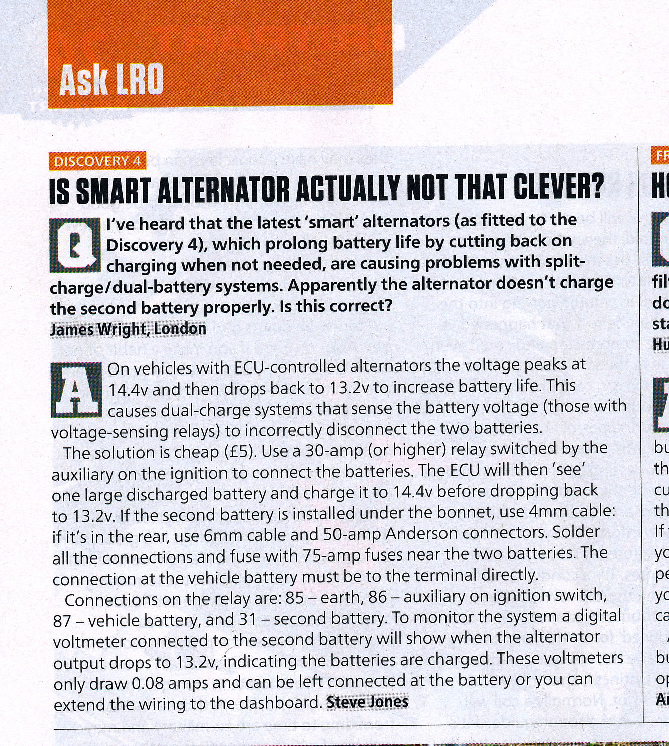
Article appeared in Land Rover Owner International magazine – September 2013. (c) LRO / Bauermedia
SCR’s as opposed to VSR’s are now more than just simple relays. Originally they had to ensure that the were ‘make before break‘ switches, which means they connected the second battery before disconnecting the starter battery, otherwise allowing the alternator to go ‘open circuit’ was a sure way of prematurely ending its life.
SCR’s now (and I don’t mean the trade name acronym used by General Electric to describe Thyristors!) use MOSFET and other technology to monitor batteries and dynamically switch and proportion charging… in fact many now incorporate some form of smart charging technology, facilities for connecting more than just two batteries and some even have shore power charging ability and AC inverters built-in. There are a number of SCR’s on the market that now also handle the alternator regulator function and require modifications to your alternator to improve charging capabilities. These however are usually more suited to marine use. One of the best companies I know off for this sort of technology is Sterling Power.
You often find ‘split charge relay’s’ in 4 x 4 vehicles that have a second battery for a 12 volt recovery winch or in boats, where they have a normal engine start battery but may have a bank of several 12 volt batteries to provide power while under sail or moored without shore power. Some top end 4 x 4’s have alternators with a dual output for handling a twin battery system. For more information about the difference between Relay’s, Voltage Sensing Relay’s and Split Charge Relay’s read my post Relay, VSR, SCR… What’s the difference?

Typical 13 pin connected caravan wiring showing habitation relay
As a fall back safety system, the caravan manufacturer will install a fuse between the caravan’s leisure battery and the 12 volt systems on board the caravan. This does two things… it protects the caravan’s 12 volt electrical system if there is an overload or fault, the second thing is does is protect the caravan wiring from damage if the habitation relay should fail and you start the tow vehicle’s engine with the caravan connected. The fuse will blow before any damage can be done by the car attempting to use the leisure battery as a source of power. This fuse is typically rated at 15 or 20 amps.
Warning!
Some people will tell you that you can check your alternator’s output by starting your engine, then disconnecting your battery to take measurements… some will tell you if you have a flat caravan battery to start your car, disconnect the good battery and connect the flat battery.
Well, if you disconnect your battery with the engine running…. your off shopping later for a new alternator. Disconnecting your battery when your engine is running is a really bad idea. You will cause voltage spikes on the tow vehicles electrical system that might just see off your ECU and radio…. it will definitely see of the diode trio in the alternator.
“OK give me all that in English…”
1 – When you plug the caravan into the car with the engine-turned off, pin 9 (13 pin) or 4 (12S) will supply a voltage to the caravan this will energise your Al-Ko ATC system if you have one fitted and on some caravans will allow you to manually switch from the caravan’s leisure battery to the tow vehicle battery. All the road lights will work. The caravan battery is NOT connected to the charging circuit (so you can’t use the caravan leisure battery to start your car if the car battery is flat!)
2 – Start the engine. This now makes pin 10 (13 pin) pin 6 (12S) live and provides power to the fridge in the caravan. It also energises the habitation relay, disconnecting the caravan leisure battery from the caravan and reconnecting it to the tow vehicle charging circuit only.
Actually is quite simple really…. even I got it then!

13 Pin or ‘Continental’ socket fitted to my Freelander
Some things to look out for….
The cables on the towing electrics should be of sufficient size to carry the current required by various components in the caravan. Typically the road lights only need a 1mm or 1.5mm square sized cable. However, the charging circuit requires a minimum of a 2.5mm square cable as does the fridge circuit. If you look at the wiring diagrams above, you will also see that there are a number of neutral or earth cables. These are kept separate in the caravan and should never be linked within the caravan. The only time these neutral or earth cables are connected is when they come together to a central earth point in the tow vehicle. These cables should also be a minimum of 2.5mm square.
If you want to install two batteries in parallel in your tow vehicle, or even in your caravan – especially if you have a heavy twin axle with a motor mover fitted, there is a right and a wrong way to do it. I’ve written a “How To: Connect Two Batteries in Parallel” guide.
For fault finding on the leisure battery charging circuit, the first step is to make sure all is well with the tow socket on the vehicle. To help with out dismantling it I’ve done a drawing showing the pin connection from the socket side….

The connections for a 13 pin towing socket seen from the socket (plug) side.
You can click on the link to down load a PDF copy: 13 Pin Towing Socket 01
Further Reading:
Understanding Watts, Amps, Volts and Ohms – A very basic introduction to some simple maths that allow you to work out power, current and resistance.
Relay, VSR, SCR… What’s the difference? – goes through the different types of relay that might be used to charge your leisure batteries.
Understanding Caravan and Tow Car Electrics
13 Pin Socket – Basic Fault Finding
ISO 11446 – 13 Pin Trailer Connections
Caravan Road Lights – Basic Fault Finding
How To: Connect Two Batteries in Parallel
.
Copyright © 2011 – 2020 Simon P Barlow – All rights reserved

Really fascinating and informative read. Thanks a million!
I have a Knaus 400LE, which was fitted with a mover and AGM 12 100aH leisure battery from new.
The Leisure battery has finally given up the ghost, so I decided to switch to the same spec, just in LiFePo4.
I had thought that my other battery was charging from the car, but when I went to remove it, I saw that they had never bothered to connect the charger, even though it has 12V starter battery input option (only via 220V).
I had thought to go with a Victron Smart 12/12 18A charger, but after reading through the posts, it doesn’t seem like a good idea with the standard towing wiring sizes., which is a pity as it seemed really straight forward to install and configure. Someone suggested the Renogy 20A which can be power limited, but it needs a D+ Ignition Terminal connection.
Am I right in thinking that this requires an extra wire between the car and the caravan, or is there some other way to do it using the standard towing wire connection?
I think your idea of using solar with an mppt controller seems like the best option, but it would be handy to get something like the Victron DC to DC charger, just a bit weaker, say 10A. There don’t seem to be many lower amp DC to DC smart chargers available.
It’s not such a problem running thicker wire through a camper, but it’s a real pain with a car and a caravan!
Thanks for any pointers!
Hi
With our old caravan I upgraded the cable to the vehicle socket to 4mm2 and from the point in the caravan where the flexible cable from the 13 pin plug transitions to the internal caravan wiring I also upgraded this to 4mm2 to get the best of what I could without too much volt drop. The next step was to install a Sterling Power wild side unit which can combine the leisure battery charging circuit AND the fridge circuit to charge the leisure battery and power the fridge. The big advantage was it took care of the voltage drop and charging profile for the AGM battery.
With the 5th Wheel, I will be installing a 50 Amp Anderson Connector and DC to DC charger ready for the upgrade to Lithium in the future. As we currently have 220 Ah of nearly new AGM, The lithium upgrade will be next year, but the 50 Amp upgrade is planned for this summer.
I have heard of a couple of people that have used cheap MPPT solar chargers sized correctly to use the charging circuit as a pseudo solar panel and charge their leisure batteries this way. In theory it should work OK and they reported good results.
The big limiting factor is the interconnect cable between the vehicle and caravan. I did a couple of tests making up a ’13 pin cable using flexible conduit and 4mm, 2.5mm & 1.5mm cables and managed to get some good results. The flexible conduit was the down side as it made the handling of the plug difficult. I did intend to have another go using a woven cable sock (usually woven out of kevlar or fireproof material (as used on some welding machines) the problem was everywhere wanted to sell me a 100 metre drum of the stuff. My testing did see me able to charge an AGM battery at 26 amps though with no issues with the 13 pin socket and plug. (apparently these are rated to 32 Amps per pin for the genuine Jager ones. However with a Euro 5 or 6 engine and smart alternator a DC to DC charger is still required.
As for a D+ Signal… you already have it in the caravan….. the fridge circuit is only powered up once the engine is running, so you can take the D+ feed from that as it is only usually 200mA that is required.
Hello,
Great articles. I’m changing from the old 7 pin (12n & 12s). Where do I earth the three earth wires?
This is a fantastic article thanks. I wish I had found it earlier. I am in NZ and have a 2014 Bailey Unicorn Cartagena caravan. The previous owner had cut off the 13-pin plug and replaced it with the common (in NZ) 7pin flat plug to suit his car. As I had a VW with the Euro 13pin socket I put it all back to standard. All good except I never quite figured out the fridge and charging while towing, although the ATC did work again. Since then I have upgraded my car to a 2016 Mitsi Pajero with only the std 7-pin flat connector – only good for road lights. I have also upgraded the van battery to 300Ah Lithium, plus inverter and DC-DC charger (60Amp). The latter is not connected yet which is why I started searching for ideas on this. I knew the 13pin wiring wouldn’t cope with a high charge such as this so was going to run separate cabling and an Anderson connector. What I didn’t know was what to do about the fridge – I didn’t even know about the habitation relay stuff until I found this article. It would be great to get some advice on how to proceed. Should I wire in a 13pin socket to the car so that at least I get all the standard stuff working, then proceed with the better charging on a separate cable? Also is it better to run this cable as a pair or use the chassis as ground? Inside the van, do I need to hook up this charging pair to the existing pin 9 wire and earth?
Hi Steve
I would go for wiring up a 13 pin socket on the vehicle.. that way you can have all the vehicle to caravan services working correctly which would make fault finding easier in the future. You would need to disconnect the leisure battery charging connection in the caravan as you have Lithium.. maybe make it so it can be connected back easily in the future… or even use it to charge a portable power bank. Next step would be to add an Anderson connector to power the 60 amp Dc-DC charger. I would add both +ve and -ve links and not use the vehicle or caravan chassis. Copper always conducts better than steel, especially for higher currents. You should not need to connect the new charging circuit to the caravan’s charing circuit.
Going this route will allow you to run the caravan as standard and run the charging side without relying on any wiring in the caravan… again making fault finding easy in the future as you can disconnect one system or the other to chase down any issues.
Hope this helps
Hi Simon,
Thanks for replying so quickly! Can you please clarify the disconnection of the leisure battery charging? It is currently connected to the standard consumer stuff – I haven’t disconnected anything, I think from memory this is a 20A charger for when on shore power, and should still work, although not optimal for Lithium. Or did you mean the existing 12v car charging circuit, and if so I would need to figure out where that goes?
Another thing is that the dc-dc charger needs another smaller cable running all the way to the car alternator D+ terminal – I assume to get the ignition-on signal. Do you think I could tap into the pin 10 fridge wire to get a similar signal?
Hi Steve
The existing car charging circuit is not really suitable for charging lithium batteries in the caravan. It could also fool your DC to DC charger as it will be putting a voltage across the battery and your DC to DC charger might think the battery is at a different stage of charging. I would therefore disconnect it. It might take a bit of circuit tracing as you actually need this supply to run a couple of things in your caravan whilst towing… although in theory your new lithium battery should do that.
As a simple test trace where the 13 core cable enters the caravan through the floor… you will usually find the road light fuse block there as well as the fridge circuit fuse and leisure battery charging fuse. Pull the fuse for the leisure battery charging circuit and check to see that everything is operating as it should when hitched up and the engine running.
Yep you can gat the D+ from the fridge wire, this is common practice. It is usually easiest to pick it up at the road light fuse box (mentioned above) as it is less intrusive on the caravan wiring if you ever change caravans and want to take your set-up to your next van.
Hi Steve
Forgot to mention… the onboard battery charger will be OK in the short term although it will never really fully charge your lithium battery. Plan for a future upgrade of a mains powered lithium charger. You can simply unplug your existing charger from the power mains power supply and plug in a lithium charger… again easy to remove if you want to change or upgrade caravans at a later date.
Thanks for all the info Simon. Much appreciated. Does anyone have a source for trailer wiring looms for 13pin socket on a Pajero/Shogun/Monterey? I can’t seem to find much info, and the local Mitsi dealers here don’t have a clue about 13-pin sockets, neither do the towbar suppliers. I was hoping there would be a standard kit available to plug into the car looms, otherwise I will have to pull off all the panels and try to figure it out manually. There’s already a 7 pin socket so I should be able to jump parts of it from there.
Great work, Simon. I am new to caravanning and wish to add a leisure battery to an Eriba so your articles are great food for thought. Regards John Holbrook
Hi,
I’ve a problem, I’ve an ace jubilee and I’ve checked the socket on my tow vehicle, it’s working but I’ve checked the fuse board in the caravan and all fuses seem in tact, any ideas why my rear lights are not working? I’ve also checked plugs.
If none of the road lights are working, I guess there is a faulty earth between the tow vehicle and road lights.
Quick check would be to run a length of wire from an earth point on the vehicle to the earth of one of the lights or the main road light earth point in the van.
Great article! I have one question though. My fridge is a 3-mode Thetford (gas, 12VDC and 230VAC). The fridge controls (“CPU”) are active without the car running (powered from pin 9, I assume) – they show and control what type of input the fridge is selected at (auto, 12V, gas or 230VAC).
So, if I add a habitation relay, which disconnects caravan 12V consumers when the voltage is active on the “fridge” pin 10, it will disconnect fridge’s controls (“CPU”). Wouldn’t that shutdown the fridge even though now the pin 10 is active?
Does this mean that in the nice graphs above “other caravan equipment” is everything *except* the fridge control (“CPU”), which should be left alone – i.e. powered by the pin 9 directly, always, disregarding the habitation relay?
Thank you! 🙂
p.s. Off topic, but I also wonder if a lithium battery won’t draw too much current from the pin 9, but will have to find that out when experimenting.
Depending on the caravan manufacturer…. as there are differences… you need the caravan ‘master’ switch on even when towing, so this allows the fridge controls and display to be powered. This supply is usually from a circuit that remains live when the habitation relay activates. This circuit also usually allows the loo to flush even when you are hooked up and your engine is running, so the caravan 12 volt is isolated EXCEPT for the fridge control and loo.
The ‘off topic’ question is really simple to answer… YES. That’s why if you install lithium you have to install a DC to DC charger… usually a 15 amp one for non adapted vehicle connections or if you have an Anderson connection you can go up to 60 Amps depending on your alternator and if its Euro 5 or Euro 6
Thank you for your reply!
The caravan is equipped with Dometic SMP301-01 AC-DC converter (it includes a switch which disconnects some 12V consumers when only on car power). I know that pin 9 wire is routed to it, but I think not pin 10 (I suspect it goes straight to the fridge). Not yet sure from which point the pin 9 wire is branched out to the fridge controls and the water pump.
Thanks for the 15A number! I was looking for the current capacity of the thin socket wires, as it’s hard to tell how many mm2 are they exactly.
I was also thinking about Victron Orion DC-DC converter/charger to cap the current. After your confirmation, looks like I should get it for lithium from the beginning 😉
Hello once again 🙂
Would you know if it’s safe to use 18A DC-DC charger for leisure LiFeYPO4 battery through the caravan’s 13-pin socket’s pin-9 cable (from what I see it’s 2.5mm2)? The “weak link” is about 2-3 meters.
The issue is I can’t find a 15A rated DC-DC charger. What I find (and trust the manufacturer) is Victron Orion 12/12-18, but 18A/0.87 efficiency=~21A constant draw.
https://www.victronenergy.com/dc-dc-converters/orion-tr-smart
This seems still doable for 2.5mm2, but on a limit…
Or maybe you know of a better suited DC-DC charger?
Thanks a lot!
p.s. For reference, the fridge on a same size pin-10 wire is drawing 16A.
No, the max is 16A for a 2.5mm cable. If you need to go above that you need to install an Anderson connector and additional cabling between the vehicle and caravan.
I’m not 100% sure. but I think that you can limit the max current draw in the software config for Victron DC to DC units.
I did look at Victron kit about 18 months ago for doing a conversion on our caravan, but pricing was silly even back then, so I stopped looking into Victron kit and software specs. I can do a similar project as I was originally planning with Renogy equipment and have a single manufacturer system for around two thirds of the cost based on current prices so that’s what I have been focusing on.
Renogy do a 20A DC to DC charger that can be current limited to 10A – see page 14 of the instructions https://www.renogy.com/content/RNG-DCC1212-20-BC/DCC1212-204060-Manual.pdf
Another DC to DC charger that I found that wouldn’t blow the 15A fuse on my towing electrics was the 2A Optimate DC. It is sufficient for the winch battery on my trailer but possibly not enough for a caravan leisure battery.
A third option would be the Sterling Wildside which overcomes the 15A fuse limit of most cars by using pin 9 and pin 10 together, plus both their earths, to double up the current capability to 30A.
In our current caravan we have a Sterling wild side unit and it has worked fantastic for about 5 years now. We are leaving it in the caravan for the next owners so are planning a totally new install in our next unit.
Curious charger that Sterling. If I understood from Sterling’s docs right, it seems to be a “buck-boost” converter? I was too thinking about combining wire 9 and wire 10 (and their negatives), but in a less-fancy way then Sterling:
Combine the wires, which gives 5 mm2. Connect DC-DC charger. Rewire fridge to take power from the leisure battery directly. This way the battery is charged from the 5 mm2 combined cables and fridge kicks in as needed (taking part of the charge).
What I find strange is that Sterling 40A model still feels too much for 2 x 2.5mm2 wires (2x15A=30A fuse).
Maybe I shall just add/wire inverter/230VAC to pin 9 and forget about thin wires 🙂
There is more to the Sterling Wildside unit… the two circuits are separate as far as the vehicle is concerned, therefore nothing can affect the vehicle.
When running on 12 volts, the power draw is constant… the fridge doesn’t “kick In” it is on all the time. (unless you have upgraded to a 12 volt compressor fridge)
The Sterling unit is rated up to 40 amps, but due to voltage drop, which increases as you approach max current through the cables will never achieve this. The clever trick is to feed just as much current to the fridge as it demands then increase the draw on the fridge feed circuit to supplement the leisure battery charging.
The smart way to get more watts to the caravan is to step up to 48 volts in the car, use a separate isolated socket then step down from 48 volts to 12 volts in the caravan. A 2.5mm cable at 48 volts/16 amps will allow 768 watts which at 12 volts would need 64 amps to achieve. Plus 48 volts you are still classed as low voltage so not come under certain regs. 48 volt “pass back” is used in some military applications.
TBH if you need to charge batteries in your caravan from your vehicle that much, just put in a 60 amp circuit and Anderson connectors and leave the rest of the wiring as standard.
If you look at ti though…. just how much driving are you going to do between boon docking locations? In Australia where a 8-10 hour or longer drives between overnight stops is normal then totally worth it… and that is what they do… a 60 or 100 amp circuit between ute and caravan. In the UK / Europe not so much. A far better way is to get as much solar on the roof as possible… it still charges while you are driving probably more than you could by charging from a running vehicle.
I looked at doing a project for high power charging from a vehicle a couple of years ago and dropped the idea due to some of the issues involved, the cost, and just how much you can actually achieve. I worked on an 8 hour drive – just how much energy could I get into the battery. For the same cost I could add a lot of solar and an MPPT charger and get more energy in 8 hours in perfect conditions, but as the solar worked during daylight and not just while the engine is running… it pays back quicker and I worked out I could reduce battery Ah capacity slightly at the same time.
In a motorhome it is completely different cost / payback model and usually worth doing.
I think you have nailed it with solar. To get 15A equivalent (~200W) from the rooftop sounds realistic even in a dull day (esp. as it’s for the duration of the whole day not just few hours of driving, as you said).
Most importantly, in this case, the caravan’s upgrade is not coupled to the car! This is the main reason why I’m not keen in Anderson plugs, boosting voltage in the wires, etc. – because it’s an upgrade to the car, which may change. I’d like Caravan to be “decoupled” 🙂
S> the fridge doesn’t “kick In” it is on all the time. (unless you have upgraded to a 12 volt compressor fridge)
No compressor here – but now I know the benefit of it 🙂 I was not aware that the fridge draw is constant, I was expecting it regulate itself similar to when on gas. Thanks for clarifying that!
S> The clever trick is to feed just as much current to the fridge as it demands then increase the draw on the fridge feed circuit to supplement the leisure battery charging.
Ah, in my case the fridge is drawing 16A, so it’s at the 2.5mm2 limit already. And if it’s constantly running then Sterling’s benefit seems diminished here.
In practice, it’s just an issue of not finding a decently priced current-matched charger. Either they are too weak (like 9A model at https://www.victronenergy.com/dc-dc-converters/orion-tr-dc-dc-converters-isolated#datasheet; or 10A of Renogy’s 1/2 capacity) or a bit over the limit (like the 18A Victron Orion-Tr Smart). Not sure if Sterling is available close-by in Europe, but also whether it’s useful in this case with 16A fridge.
I already knew most of this but still read it! Very comprehensive and well written
Thank you for your detailed insight into towing electrics. I’ve have a problem with my Chrysler 300c with ECS vehicle specific towing wiring whereby a 15 amp fuse blows and I loose all caravan road lights. I replaced 2 modules did a test run ,all seemed well. Came to going on holiday, caravan hitched up, switched on lights, immediately blew the 15 amp fuse. Had eureka moment and realised the only difference between the test run and holiday mode is the fridge is on auto to run on 12 v from car. Switched off fridge went on hols and back 360 miles with lights on no problem. ECS tech support respond but not at all helpful. I now need to chase the wiring to understand how the fridge is using the same circuit as the lights and try to correct it. If you have come across this problem before I would be grateful of any tips you might have. My caravan is a Coachman Laser with a Thetford n3175 fridge /freezer which draws approx 15 amps on 12 volts. Thanks Barry Daniels
Hi Barry
If I read this right, the fridge bring on blows a fuse in the vehicle which causes you to loose road lights.
OK, I would tend to think that the 15 A fuse that blows is doing two jobs… supplying the module that controls the road lights AND supplying pin 10 which is the fridge feed when the engine is on. I believe there should be two 15A fuses located in the ECS loom near the vehicle battery. One is for the leisure battery charging circuit and the other should be for the fridge circuit.
I think that one of the modules fitted in the rear of the vehicle is powered and runs the caravan road lights based on signals from the vehicle rear light loom and the cable that runs that also then goes to pin 9 in the 13 pin socket.
Initially from the details you have given, the only way I could see this happening is if the wire loom is incorrectly terminated in the 13 pin socket and pin 9 and pin 10 are the wrong way round. I’d check that first, then if that was OK I’d check that pins 9 and 10 weren’t reversed on the caravan.
Let me know how you get on.
EDIT: I think that the fridge circuit may be an optional add on and the ECS wiring loom has a connector on it that has to be connected to a separate supply…. maybe this has been connected to one of the ECS main feeds? It would be worth downloading the installation manual for your specific kit if you haven’t got it from the ECS web site and just checking.
Thank you Simon for your quick reply, I had just finished sorting the problem using your diagrams of the car wiring. I exposed all the modules and relays and traced the wire from the blowing fuse to the relay common and then the normally open to pin 10 on the socket. I found that ECS had piggy backed the 12 v from the common to the 2 towing modules and there lies the problem. So I cut the feed and piggy back from the common and joined them together to feed the modules and then ran a new fused wire from the battery to the common to feed the fridge when the relay operates. So I now have 3 12v fused supplies from the battery (which is in the boot) 1 for the fridge etc, 1 for the road lights and one for the ATC etc and one smaller wire from an ignition 12v operating the relay. I connected it to the caravan, powered the fridge on battery and switched on road lights, brake lights, hazard lights, rear fog lights and started the car and all is working. I have used 30 amp fuse holders for both the lights amd the fridge with 20 amp fuses installed. So many thanks for your excellent article and advice, it really helped me understand the wiring and sort the problem out.
Hi Barry
Well done! So glad you are all sorted…. it did have me thinking after I posted my reply that it could be a bit of a nightmare to trace the fault if it wasn’t that.
Hi Simon
I’ve recently purchased a Knaus Starclass 695 van equipped with a Dometic RMD8551 3-way fridge freezer (170watts operating on 12v). Imagine my dismay when I discovered the fridge wasn’t operating on 12v whilst towing because it wasn’t connected to do so. This despite the fridge having a 12v heating element and the van’s 12v control unit (Schaudt CVS410) having a suitable 12v fridge terminal – they are just not connected. My supplying dealer was also initially surprised but was informed by Knaus that the fridge wasn’t connected deliberately because of concerns that the fridge could draw up to 16amps and the 13 pin towing plug/socket and car electrical circuit supplying it might be inadequate to support this.
My car (Porsche Cayenne) tow circuits to pins 9/10 are fused at 20amps and surely the Jaegar 13 pin setup should be more than adequate. The fridge is a standard model and used by several van manufacturers who do connect it. Can you see any justification for Knaus’s stance or any reason why I shouldn’t connect the fridge?
Hi Col
I’ve heard of this before with Knaus…. in fact a couple of years ago we nearly bought a Starclass and this is when I first came across it. You can connect it and should not have any problems with a Porsche Pepper. The 13 pin connector is rated above 20 Amps per pin…( I seem to recall it was rated at 32 Amps per pin, don’t quote me on that though!). I installed a Sterling Wildside unit to run the fridge and charge the battery and that pulls 20 Amps per pin through the leisure battery charing circuit and fridge circuit. Both these are fused at 20 Amps in the vehicle. The standard for wiring tow vehicle electrics is 2.5 mm2 cable for the fridge and leisure battery charging and earth returns, so you are not going to melt anything.
Thanks Simon – that is very reassuring and confirms my feeling that Knaus are just being unnecessarily cautious. It gives me further confidence to insist my dealer makes the necessary connection. Once connected I will be able to assess if I have a further issue in terms of smart alternator behaviour, in which case I will follow your good self and install a Wildside.
Can I leave my battery charger switched on when plugged into site mains?
Hi Peter
If you mean the caravans internal battery charger then yes, that is what it is designed for both as a charger and 12 volt supply for the caravan.
Hi Simon , I have a 2013 Bailey Unicorn cadiz towed by a 2007 Mercedes Vito 115cdi. Problem i am having is when connecting 13 pin. Road lights , Atc work . But with engine running all 12v lights inside caravan still work, also battery voltage on screen just shows me around 12.5 to 12.8v. so dont think lesuire battery is charging. Also the fridge doesn’t get very cold while travelling. Do you have any idea what could be the problem or is this normal? Thanks Ashley
Hi Ashley
Had a couple of problems reported before with Vito’s…. just trace the 13 pin socket wiring back where it enters the vehicle and double check the earth’s for the fridge and charging circuits. People have had issues and reported corrosion round the earth point which caused voltage drop on the fridge and charging circuits.
After that, it would be worth checking that the earth’s from the 13 pin plug are all OK back to where the flexible 13 core cable enters the caravan and joins up to the caravan’s internal wiring. Again I’ve had some owners of older Bailey caravans report issues here too.
Hi Simon, checked pin 10 with my multimeter and getting no voltage at all from it when engine running, is there anything I can check from this? Could it be a faulty tec3m? Relay thanks Ashley
Hi Ashley
Probably, never seen one of those relays last more than a few months. Never installed one but removed plenty.
What relay would you reccomend?
I don’t normally recommend fitting a VSR as there are so many issues. However this is the one I’d go for… https://www.12voltplanet.co.uk/voltage-sensitive-relay-12v-140a.html
It needs to be mounted next to the battery and a new lead running back to the 13 pin socket. If you don’t mount it next to the battery is can’t correctly sense the battery voltage (that’s the big problem with most of the pre-wired units on the market as they are designed to install at the rear and don’t take into account the voltage drop on the thin cable they are normally supplied with in the loom)
I’d suggest a minimus of 4mm sq cable from the relay to the 13 pin socket…6mm would be better. While you are running this, it would be good to upgrade the leisure battery charging feed too to the same size cable. Both need to be fused at 20 amps each near the vehicle battery.
P.S. if the lights are on in the caravan with the engine running then the habitation relay is not being triggered by the fridge circuit voltage…. so you would not gt any leisure battery charging either. So I’d concentrate checking out the fridge circuit first.
Hi
This post has been very good reading and really clarifies how the electrical systems need to be wired. We have just bought a caravan and with COVID-19, our local trailer shop is closed. So I going to have a go at wiring a 12(s) socket to my 2005 Mitsubishi Shogun Sport (I already have a 12 (n)).
I had two questions on the live feeds:
1 – do you seen any problem with using a 20 amp fuse tap (based on the manufacturer specification for the tail wire) for the switched live? Could I use the same for the permanent live?
2 – if I take permanent live direct from the battery, what is the best way to connect that live – I can’t find connectors to the battery terminals for 2.5mm cable so I assume it is wound onto existing connectors and bolted down with them?
I will use 15 amp fuses on both live circuits, either via the fuse tap or inline fuses.
Any help on the above would be much appreciated.
Many thanks.
Dan
Hi Dan
Fuse taps are OK up to a point, once you get to 20 amps realistically you are approaching the top end of what they can do. If you tap a circuit that is already rated for 20 amps you need to be sure that the cable feeding this is rated for the original load it was designed for and the additional load you want to put on it. I think that the Shogan had a spare fuse slot that supplied a switched feed for a trailer. Have a look in the handbook for a listing of fuses…. one may state trailer supply (or something similar) and on the vehicle it won’t have a fuse in that position.
For connecting to the battery, there are crimp terminals that are designed for 2.5mm cable and have oversize “O” ends specifically for fitting under the nut that holds battery terminal clamps.
If you have a look on my Amazon links page… https://caravanchronicles.com/caravan-chronicles-shop/ There is an assortment box of crimp terminals that have ring terminals that fit onto most battery terminal bolts. Halfords also sell the correct size in blister packs. Alternatively there are replacement battery terminal clamps that are designed to take accessory cables.
On out Freelander I used 15 amp fuses for both circuits without any issues.
I think I’m going to echo the sentiment of an earlier post … ‘returning from the brink of frustrated madness’.. although my journey back has yet to begin. Also, excellent site!.
I have a Bailey Ancona (2018) with a factory fitted ALCO ATC – it worked perfectly with my previous vehicle (UK Toyota Avensis 12 plate with a Whitter tow bar). ATC powered up every time I plugged the 13 pin connector in (suggesting the system is powered from pin 9). All good, until I swap my vehicle a few months back to a 17 plate Honda CRV (UK) with a Honda fitted tow bar and electrics (fitted from new). I plugged the 13 pin connector in expecting to hear the ATC system do its system check – but nothing.
I then began to read up on matter – first I checked that the ATC was still operational (by plugging it into a friends car). All fine. So this pointed to the car – and then I begin to read reports of pins 9 and 13 not being connected. So I tested the output on pin 9/13 and got zero volts. Then I read if I have my road lights on, I should get a voltage. I tried this and it worked the firs time, but not since, and still no ATC. I should add that all road lights are working fine.
I spoke to my local Honda Dealer in Coventry and they were little help (just before COVID lockdown). ‘We didn’t fit it (it was another Honda Dealership) and its out of warranty (after market Honda equipment has a 12 month warranty)’. I suspect I do need to take the car to Honda to have it checked out – but I think they lack the expertise in-house to know where to look.
Has anyone else had a similar experience with the CRV. I have pondered having the Honda fitted electrics removed and an aftermarket system fitted (a bit extreme I know), but I have six months of my vehicle warranty left and that would likely invalidate it.
Any help or advice gratefully received.
Hi Simon,
Thanks so much for your guides and information, I am not only returning from the brink of frustrated madness… But also learning!.
My query is this… I bought an Ace Supreme Twinstar 2004, and I am having terrible problems with the electrics and charging the Leisure battery… If the 12n and 12s have been connected and engine running, would this override the selector in the van? I can’t seem to power the 12v from the 240 regardless of switch position, and also have very intermittent battery level readings, could this be down to a stuck or incorrect relay sequence? I.e previous owner switching the van supply whilst still connected and engine running?
Would a charger directly from the 240v effectively bypass the habitation relay, and/or the selector switch in the van?.
I hope this makes sense!? And thanks in advance.
Hi Robert
I’m not 100% familiar with the Ace Supreme Twinstar, however as I understand it if the engine is running, the habitation relay should activate and render the van-off-vehicle override switch inop. only when the engine is off and the habitation relay has disengaged will the van-off-vehicle override selector work.
I think that the old power unit in these vans was prone to failure… and it would be worth checking that there is actually a 12 volt output when it’s powered off 240 volts.
I would tend to suspect that the fluctuating voltage is down to corroded connections through out the van. It would be worth starting at the 12N and 12S working backwards and checking al the connections. A fave one on these is the actually connections to the back of the override switch.
Hi Simon
I forgot to say in my first post that your blog is the best explanation of the Leisure battery and associated circuitry that I have found, thanks very much.
I have taken on board your comments, which reflect where I was heading, I just needed some expert opinion.
I have now got clear how the caravan battery gets its power.
One final question, regarding the power draw through pin 9, when the caravan is connected up and the tug motor running.
The ALKO ATC unit draws just over 14amps when it is required to operate, very little otherwise, and with the battery connected through pin 9 as well there could be quite a draw there as well. So I am wondering what amperage converter I should buy for this load, 14 amps plus ? batt draw, and what could the potential max load through this pin 9 be?
Hi Mark
In standby mode the Alko ATC draws very little current, however when activated as it is powered by the circuit that supplies the leisure battery charging, current is drawn directly from the circuit so in effect both the vehicle and the leisure battery supply the current.
Hi Simon,
A bit of a different question for you. I am purchasing a 2018 bailey unicorn cadiz, and have to modify my towcar to provide the permanent and ignition switched power.
Now the tricky bit is that my tow car is a 24volt Nissan safari 4wd. This is an old school 1990 model, no smart alternators or computer to deal with.
I already have an even charger fitted to equalise the charge across the two 12v, series wired, safari batteries, and this allows me to take one 12volts permanent feed off to supply the caravan. I intend to use this feed to supply pin 9 the 12v permanent supply for the ATC braking.
Now I am wondering how to supply the 15 amps or so of power to Pin 10, the ignition switched feed to the fridge and battery charger. I can buy a 24volt DC/DC 30amp converter which I could mount in the boot to supply 13.8 volts to the pin 10. I assume that I would use a relay to switch the power on to this unit. With a constant 13.8volts or so depending on cabling losses I wonder how this would affect the caravan battery charging, or would the battery even charge at all.
If you can think of any better ideas or improvements I would be grateful.
Hi Mark
Pin 9 is the 12 volt permanent supply and should provide power for both Alko ATC and the Leisure Battery charging circuit. Pin 10 (ignition switched) provides power for the fridge. This circuit also operates the habitation relay which effectively disconnects the leisure battery from he caravan and connects it to the charging circuit.
Pin 9 supplies the leisure battery AND Alko ATC so that in the event of the voltage drop being significant from the vehicle it can draw power from the leisure battery as well. So in reality all you need is a DC to DC, 24 to 12 supply for the fridge… about 15 Amps.
If I was wiring this set up, rather than run a 12 volt circuit from one of your vehicle batteries, I’d put two smaller 24 to 12 volt units in the rear of the vehicle (keeping everything in the vehicle 24 volt), one for each of the circuits (pin9 and pin 10) this will reduce the voltage drop between the vehicle and caravan. I’d put an ignition controlled relay on the 24 volt side of the unit supplying pin 10.
Now… you could use one 24 to 12 – 30Amp unit to supply both circuits. Split the 12 volt output, so one side provides power to Pin 9 and the other supplies pin 10 via an ignition controlled relay.
If you can mount the 24 to12 unit(s) in the rear of the vehicle and keep the 12 volt cabling to the tow socket to a minimum using 4mm cable, the voltage drop will be minimised and you should be able to charge the leisure battery.
An upgrade for the future might be to put a 12 volt DC to DC leisure battery charger in the caravan (that’s what I have done) to provide multistage charging to the leisure battery.
However you configure it you need to keep in mind that if you plug any other trailer/caravan in to the vehicle it should work and conversely you want to be able to plug your caravan into any tow vehicle and work.
PS… remember to keep the ground (-ve) circuits separate within the caravan and double check on the DC to DC unit(s) if the output -ve can be connected to vehicle ground (-ve) or if they have to remain ‘floating’
Thanks again, Simon.
The cable harness on the car is a Volvo one, together with what they call a ‘trailer module’ which handles the signalling to the 13 pin socket. The software update was done by my local Volvo dealer whom I know well so I’m content that they did their bit OK. In fact I can’t see that it could be done wrong as the software would either install or it wouldn’t. But, although the car has a 13 pin socket, the trailer only has a single 12N socket at the moment so I’ve been using a 13 to 12N and 12S adapter lead and testing things with the 12N plug from the trailer in the 12N socket on the adapter.
I think I need to follow up on a couple of different things. First, I will ask Volvo how the trailer wiring is supposed to work. I’ll also remove the interior trim from the back of the car and check that the leads from the cable harness are plugged into the right sockets in the trailer module. There are nine wires from the harness plugged into the module listed as reversing lamps, ground, power supply, right parking (side) lamp, left (side) parking lamp, right indicator lamp, left indicator lamp, brake lamp, fog lights. The module has provision for twelve wires to connect which suggests that the ‘fridge’ circuit may be missing, or at least not constrained to only operating when the engine is running and simply ignition controlled. There are three unused sockets on the module which suggest that in other models it may have the full specification of wiring. There are also two other plugs with two terminals each that plug into the module but it’s not clear what they do. I’ll also have a chat with the guys who did the install as they are very experienced and might have some idea what has happened.
More research needed but clearly as it is it can’t be used to charge the battery!
Best
Simon
Simon,
I had to get a Volvo software update once the cable harness was installed but I find that pin 10 (the ‘fridge’ circuit) is live once the ignition is on and doesn’t get cut out when cranking the engine. The effect of this would seem to be that with a flat car battery, attempting to start the car would draw on the trailer battery since the fridge circuit would be live and thus the charging circuit would also be ‘live’.
Am I missing something?
Regards
Simon
Hi Simon
Hmm…. sounds like something is not right. You are right in your conclusion.
The first thing to check is the voltage on pin 10… then with the voltmeter still attached get someone to start the car.. or turn it over. You might find that before the starter relay engages, the vehicle disconnects the supply to pin 10 therefore disconnecting the leisure battery from the charging circuit. Some early Land Rover Discovery OEM units had this “feature”.
Also check if Pin 10 is live with the key out of the ignition… if it is, this means that the fridge will be drawing current from the vehicle even when parked up and key out. Quick way to drain the vehicle battery.
I’m not too familiar with the Volvo setup… I’ll make an assumption that it is either a Volvo product or an OEM version produced by someone like Wesfalia. If it’s Volvo, check back with them, if it’s an OEM one, check to make sure the Volvo normal towing software upgrade is suitable. It might be that the OEM manufacturer has its own settings for the upgrade.
Let me know how you get on… It may be useful to other Volvo drivers.
Simon
Just re-read your comment… missed the point you had made about the circuit not cutting out when cranking.
This is def not right. After doing a bit of digging round and checking Volvo specs, you need to take this back to the installer as something is wired or programmed wrong.
S
Hi Simon,
This is perfect! Thank you so much for taking the trouble to answer my very basic questions. I now feel I can talk to the towbar fitter next week in the knowledge that I know what I needs to be done to give me the trailer battery charging that I’ll need.
Many thanks again,
Simon
Hi Simon
If you haven’t had your tow bar fitted yet, go for a 13 pin socket rather than 1 12N and 12S… it is far superior and has all the connections in one fitting. It is standard now and if you tell your tow bar installer you want it for towing a caravan… so installing to ISO 11446 it will ensure you have all the right connections…
It is a simple matter then to convert the trailer to a 13 pin plug that contains all the correct connections for your charging circuit.
Hi Simon,
I’d thought of that but the trailer (with a 12N plug) is in England and I am going over from Belfast to collect it. I’ll then need to add in the wiring for the battery charging once I get it home and it seemed easier to do that via a separate harness and a 12S plug and socket. If I fit a 13 pin socket on the car I’ll need an adapter to collect the trailer and then will have to convert the trailer to 13 pin and add the extra charging harness into the plug as well. Using the two 7 pin sockets and plugs seems easiest.
Or a cheap adaptor that plugs into the 13 pin socket and allows a 12N to plug in… just a thought.
True. And I could then get the towbar guys to wire up a 13 pin plug on the trailer and add on a small loom for pins 9, 10, 11 and 13.
Thanks again
Simon
Simon,
When I draw out the wiring I’d need for the trailer it’s just a relay activated by the fridge circuit which switches in the battery charging circuit. To keep it simple, is there any technical/electrical reason why I couldn’t just use the fridge circuit to charge the battery and skip the relay and the additional pair of wires?
No reason at all…. but you stand a good chance of screwing the vehicle electrics.
The fridge circuit is controlled by the vehicle and is not designed to be back fed 12 volts which you will be doing.
If it dosen’t fry the vehicle electrics, maybe the vehicle will drain the leisure battery. I have no idea what will happen as its not something I’d countenance and have never considered.
The habitation relay is put there for a reason and it is controlled by the vehicle in the way it is for a reason.
OK, I understand what you mean about the fridge circuit not being designed to be connected to another 12v supply. Presumably the battery charge circuit is designed to cope with this.
Thanks again.
Simon
The battery charging circuit has protection for the vehicle. The fridge circuit may or may not have protection. Both will certainly have 15 or 20 amp fuses. On modern vehicles it is probably sold state switching within the electronics command module or within the OEM towing electrics add on module. Long gone are the days of just adding wires to the tail lights and running a wire up front to the battery.
As an aside, The owner of a tow bar fitting company related a story late last year to me about one of the ‘apprentices’ forgetting to change his multimeter from current setting to voltage setting and he accidentally probed across the fridge circuit and battery charging circuit on a new vehicle that was having a tow bar fitted.
The result was the owner was without his vehicle for three weeks and it cost over £2600 for a new ECU, master electronics control module and sensor module. In addition the vehicle had to be transported back to the main dealer to have the software re-uploaded. I’ve not mentioned the make as these vehicles are particularly sensitive to their electronics being played about with.
PS… don’t forget that your tow vehicle if less 6 or 7 years old will probably require a main dealer software re-program if your tow bar fitter can’t do it.
Thankfully my tow car is a 10 year old Volvo V50 and as far as I’ve been able to determine no software update is required. The guys who are fitting the tow bar and electrics are very experienced and reputable so I’ve no concerns that they’ll get it wrong.
As long as they wire the socket fully, that will allow me to get the trailer home and then they can make up the trailer charging loom with the relay!
Thanks.
Ah, so the 30 amp relay would go on the trailer and be triggered by the fridge circuit on pin 6 to connect the battery to pin 4? Although the same result could presumably be achieved by wiring the trailer so that pin 6 did the charging rather than pin 4. That wouldn’t preclude hooking up to a different tow car. But I’ll read the articles you’ve linked to as I mentioned I’m sure they’ll be helpful.
Thanks again.
Only use 4 for charging and 6 for triggering the habitation relay.
Simple reason, some ECU’s current limit 6 to about 12 to 14 amps as that is all a fridge generally draws, where 4 is not usually limited (except by voltage drop so use 4mm2 cable as a minimum).
Also a lot of vehicles can turn off 6 to reduce the electrical load on the vehicle… say in winter when you first start… put the lights on, turn the rear screen de-mist on, turn the screen blower on full. To make sure the vehicle battery is recharged ready for the next engine start, the vehicle ‘dumps’ excess load and this will be the fridge and leisure battery charging and reinstates them when the electrical load in the vehicle reduces or the starting battery reaches a pre-determined charge level.
There are a few other things as well now… some vehicles detect the leisure battery connecting to determine if a caravan or simple trailer is connected…( some have switches in the 13 pin sockets to/as well to detect when trailer is plugged in!) which affects the ABS system, ESC system, traction control points and shift points in an auto gearbox…
Keeping to the standard for 4 and 6 will hopefully future proof your installation.
There is some chatter going on at the moment saying that any trailer over 750Kg capacity (i.e. a braked trailer) will be required to have something similar to an MOT each year. Apparently this is being driven by a few countries in Europe that have separate licensing for trailers and want to have a safety check as part of that. So again keeping to convention might just pay off in a few years time.
Simon,
This is all very helpful – thank you. My trailer is for a vintage – 1930s – car and my understanding of car electrics hasn’t had to extend much beyond three brush dynamos and cut outs (no regulators!). So the idea that the tow car can potentially sense what’s connected to it and adjust its alternator output accordingly is a novel one, to say the least!
But I’m nearly there. If pin 6 is the trigger for the relay to connect the leisure battery to pin 4, and thus to the tow car’s battery for charging, is pin 6 live as soon as the ignition is switched on or is it somehow constrained until the engine is running? If not constrained, wouldn’t cranking the tow car engine draw on the leisure battery via pin 4 with potentially disasterous results?
Hi Simon
Pin 6 on the vehicle was originally controlled by the ignition light… I.e. when the alternator (or dynamo!) was producing enough voltage it would extinguish the old ‘ign’ light. Now pin 6 is controlled by the vehicle’s ECU.
Pin 6 will not have any voltage on it until the engine is running.
Thanks again! So a 30 amp relay to connect pin 4 to the tow car’s electrics, with the relay triggered by the fridge circuit on pin 6? Or could I just use pin 6 to charge the battery since the pre 1998 12S wiring used an ignition controlled supply for battery charging?
You need to stick to the standard convention of wiring pin-out’s and how a caravan would handle it. Main reason, if by chance you needed to tow the trailer with a replacement vehicle, you would want to know it worked no matter what and would not harm the new vehicle. Additionally, you don’t want to modify the existing tow vehicle so it is non standard… which could become problematical with current or future vehicle testing procedures.
Have a read of https://caravanchronicles.com/guides/understanding-caravan-and-tow-car-electrics/
and…
Vehicles over the last few years have become very clever… A few years ago Land Rover owners first started noticing issues when Land Rover programmed their alternators to turn off when the vehicle battery was fully charged and effectively took away the vehicles ability to charge leisure batteries. In my Amarok, when I brake the alternator provides a huge amount of engine braking by dumping over 2Kw of energy into the AGM starting battery, therefore this battery can only be ever charged up to 80% capacity… limited and controlled by the vehicle’s ECU.This in turn means that technically I can only ever charge my leisure battery to 80% capacity. There are products that overcome this limitation on the market.
It’s therefore imperative you follow the same ‘rules’ that the caravan designers have to make sure the electrics on the trailer are compliant.
In Europe/UK by law any electrical devices on a trailer (and this includes your winch) MUST be disconnected from the tow vehicle to ensure that they cannot interfere with the vehicles electrical or safety systems when being towed. The exception being the trailer road lights, obviously. That is why the habitation relay is there… to disconnect the caravan from the vehicle battery and leisure battery.
In the caravan context it really is a change over switch… changing over the leisure battery connection from the tow vehicle charging circuit to the caravan services circuit.
In your case the winch isolation switch will perform this isolation from the leisure battery and the habitation relay will simply connect to the vehicle charging circuit when it receives a voltage from the fridge circuit once the engine is running.
Liability wise I can’t tell you exactly how to connect it up… I can only point you in the direction of articles I’ve written as explanations of how things work.
Hello Simon,
I found this article while searching for information on how to charge a deep cycle/leisure battery on a car transporter trailer, the battery being used to power an electric winch. Obviously most of the information about habilitation relays and so on isn’t relevant to my situation but it would seem that if my 12S socket is correctly wired to the post 1998 specification, I can simply connect pin 4 to the trailer battery positive terminal and pin 3 to the negative (earth) terminal of the battery and let the alternator of the tow car sort out the charging levels. Is that correct? If so, what is the effect of pin 4 being permanently live when the tow car is connected but not running; and if not, can you explain what I should do?
Any advice would be much appreciated.
Hi Simon
Have a read of this… https://caravanchronicles.com/2014/07/25/car-trailer-mod/
I wrote it a few years ago to help out a German chap who towed his classic sportswear on a twin axle car trailer behind an American RV.
If you look at the electrical drawing it should give you an idea of how to configure a set up for a winch battery. You do however need to take into account that feed back from the winch battery to the tow vehicle battery must be stopped when starting the tow vehicle.
Many thanks, Simon, for such a speedy reply. However, this seems to be overkill for what I need as I would only be using one battery. What I struggle to understand is how in a caravan the leisure battery is apparently charged via the always live pin 4 with no leak back to the tow car. But perhaps that is achieved by the circuitry in the caravan? Would some sort of voltage sensing relay achieve what I need?
Hi Simon
In a caravan there is a relay called a habitation relay. This is triggered by the fridge circuit becoming live…. which only happens when the tow vehicle engine is running. Once the habitation relay is triggered this then allows the connection from the tow vehicle to the leisure battery in the caravan to connect.
A voltage sensing relay is not the way forward as most cannot protect against the leisure battery staying to supply starting current if the vehicle starter battery is low.
A simple 30 amp automotive relay can be used.
Hi Simon,
You helped me out before on my previous tow car regarding the fitting of a relay in the car, using the alternator light to trigger it.
That fitment went well until I decided to go and change the car! I managed to remove the relay and fuses I’d fitted and have tried to do the same on a 2008 Honda CRV.
What’s happening though is that when the relay is getting power nothing happens, no click no movement of the contacts (I took the cover off to check). I tested it direct to the battery and it works fine. So when I tried it through the new wiring again, I tested the voltage and gave it a direct earth to the battery, and it’s pulling the volts down from over 13 to just over one volt, but not energising, I then realised the battery (alternator) light is on, and when I disconnect the relay with the engine still running the battery light goes out.
So I conclude that the power is going so low as to allow the battery light to come on, but I don’t understand why the relay won’t work?
Have you got any ideas?
Kind regards
Gareth
Hi again,
Further to my previous comment, I’ve been thinking about the problem, and it’s occurred to me that surely the battery light can only come on being earthed, and yet I measured a voltage as I explained.
So now I’m wondering if I’ve inadvertently hooked into the exciter wire for the alternator not the charge light, and the reason battery light came on was because I’d interrupted the alternators ability to make power?
Cheers
Gareth
I’ve now come across the idea that if the car is CAN bus, then there could be a signal sent to the regulator which is pulled to earth if a problem occurs, telling the ecu to put the charge light on.
All my research tells me my CV R shouldn’t have this but it would explain my symptoms.
If I find that the case, is it possible to use a bypass relay to take that signal to then output a usable 12v which I can connect to the original relay I wanted to use?
Gareth
Hi
Yep I don’t see why not… might need a transistor to use as a switch to operate the relay… or a blocking diode to catch the back emf across the relay coil.
I am considering buying a caravan and towing it with our VW Hillside Leisure conversion campervan. We have never owned a caravan before and it has been a steep learning curve as regards trying to get a tow bar fitted with correct wiring etc. I was interested to read this article about charging the leisure battery of the caravan and it made me wonder what will happen as regards to leisure batteries when I drive the van with the caravan in tow. Will both the leisure battery in the campervan and in the caravan be charged while driving or is there some way to disconnect the campervan battery so that only the caravan battery charges? I can turn off the fridge in the campervan so no problem there. I apologise if this is a silly question but I am finding it hard to find answers on-line. Thank you. Linda
Hi Linda
Sorry for the delay in replying….
I’ve done a bit of checking and if you have a standard 13 pin OEM electrical tow bar package fitted you will not have any problems charging the leisure battery in the caravan. The camper van leisure battery will charge via the existing electrical installation and the tow bar electrics will be wired in the camper van so that the caravan is charged. I would suggest going for a quality electrical system such as one from Westfalia.
My caravan control panel is showing 13.6 whilst plugged into the mains, is this normal?
Regards Peter.
Hi Peter
This is normal, 13.6 is about right for maintaining/charging the leisure battery
Ok so all the items turned up and I’ve fitted and wired it all up, using your diagram to test the 13 pin plug, everything checks out, just need to try it on the caravan soon.
One thing having a permanent live pin (9), slightly puts me on edge, I know until it’s earthed it’s not really doing anything and it has a 15 amp fuse close to the car battery in case, but still am I worrying over nothing?
Hi Gareth
After 5 years of having a 13 pin socket fitted to two vehicles, I have never had an issue with a permanently live pin. I did keep thinking about it in the early days but kind of forgot about it after a while.
I did make up a lead that allows me to plug in my smart charger for winter battery maintenance and it doubles as a connection for a 12 volt LED flood light.
That’s great, just need to forget about it lol.
Good idea about other users for that connection!
Hi Simon,
It’s Gareth, I’ve now got my own blog hence the new name!
Just wanted to let you know, the 13 pin socket all works on the caravan, and as I have a Freedom caravan, it didn’t have a habitation relay, in fact it doesn’t come with a leisure battery as standard, I added one and the fridge and charging circuits all work too.
One strange thing I discovered was that pin 9 & 10 had been connected together within the caravan, I have no idea why it would be set up like that, but using your write up, I have successfully separated the two circuits, and fitted the relay, so all is good, I’ve written a blog about it to hopefully help other Freedom owners.
So thanks for all your time and research and helpful information and replies that have helped me.
Cheers
Gareth
Hi all, I have bought an old caravan and the 12v system and supply was not up to scratch, it was a small ex-computer component testing thing, which couldn’t even power the old lighting let alone anything else. I took that out and installed a leisure battery with a smart charger and also upgraded all the florescent lighting to LED which works a treat, so bright, BUT I also installed a car stereo, which I have been fitting for years and I am also pretty good with wiring, but thus time I am at a loss as to what is happening and why.
All lighting is fine until I turn on the stereo then they blink when it turns on and the blinking gets worse as the volume is turned up, the more the bass etc the worse the blinking in time with the music. I have checked all connections and all is fine. The water heater switch also works off the 12v and when that is switched on they blink but not too much. I must say that I have grabbed the power for the stereo from the lighting system, which most people seem to do and do not have this issue! Any idea’s anyone?
Cheers, Craig!
Hi Craig
At a quick guess the wiring is too thin. A car stereo amp pulls more current on the bass notes and as the current increases, the voltage drop on thin cable will be noticeable as flickering.
Two things you need to do – first increase the size of the main cables from the battery to at least 6mm square supplying the main fuses and to 4mm square
supplying the stereo.
Second – install a voltage regulator on the lighting circuit. Not all LED lights have protection from voltage fluctuations and as a battery charger can output over 14 volts it can cause cheap LED lights that don’t have a voltage regulator built in to fail.
Hi Simon, many thanks for the input. I have sorted this now by simply wiring the radio direct to the battery, it has been spliced into the light circuitry which as you say is not meant for heavy drain items!
Works a treat now, albeit with more agro than I wanted, but still it is in and a neat job done!
Many thanks for your reply.
Hi Simon,
Thanks for the lead, I’ll see if I can discover a fuse or wire for that purpose.
Update: I’ve found the connection at the alternator for the battery light on the instrument panel, I’ve confirmed it is 0v when the ignition is off or turned on but not started, I then started the car and read the 14v at this wire.
So I’ll get a relay to be connected to this wire, I guess a fuse just before the relay might be a good idea?
Thanks again for your hints and help
Hi Gareth
Good news!
Sounds like you are all on the way, I would put a 3 or 5 amp fuse near the alternator to protect from accidental shorting.
Good idea, I’ll start getting the parts together and then update on how it all goes 👍
Hi Simon,
Brilliant write up of the caravan electrical circuits and charging, I’ve been getting my head around how it all works as I intend to fit a 13 pin socket to my 2006 Toyota Corolla.
Could I ask, if my vehicles alternator is rated at 80 amps, would this be sufficient to use the modern wiring of having pin 9 permanent live, and the habitation relay activated from pin 10 to switch over to the charging circuit, and connecting both batteries for charging? In other words, does my alternator put out enough to charge both batteries? I had thought about fitting a VSR for this reason, but would prefer to do it how you’ve explained above.
Many thanks
Gareth
Hi Gareth
A 90 Amp alternator will be well within capacity for looking after the vehicle battery and electrics and charging a leisure battery in the caravan.
Thanks Simon, and 80 amp is presumably alright too 😂.
I’ve decided the best way for me to ‘trigger’ the habitation relay is to use a vsr relay to do that and power the fridge, as I can’t think of how to activate a regular relay from my cars ignition only when the engine is running? I could probably adjust it to work fairly soon after the car has started.
Does that sound reasonable?
Hi Gareth
80 Amp will be OK. Do a search on the internet for wiring info for your car. There should be a fuse that only goes live when the engine is running, not just when the ignition is turned on. Or check with a multimeter. You can then use the output side of this to trigger a standard 30 Amp relay. A relay draws very little current so won’t affect the circuit you trigger it with.
hi i have a bailey pageant bordeaux 2006 model when i try to run fridge while towing it does not work,
it starts to run when i plug into car but after about 20seconds i hear a click and it stops charging and operating fridge any help would be appreciated thanks
Hi David
I have a suspicion that your vehicle towing electrics might be wired with a voltage sensing relay. It sounds like as soon as the vehicle battery is charged the vehicle’s ECU goes into ECO mode and drops the output voltage of the alternator to save fuel, when the voltage drops in the vehicle, the voltage sensing relay ‘thinks’ the engine is not running turning off the supply to the fridge circuit and that in turn causes the habitation relay in the caravan to turn off, disconnecting the leisure battery from the charging circuit. I’d get it confirmed that you do have a voltage sensing relay in the vehicle first. Some can be adjusted, some can’t. The correct way to wire these vehicles is by a relay controlled by the ECU.
Is it OK to connect a charger to McLouis Tandy 640 G with a flat battery while the MH is connected to the mains?
Hi Stephen
I assume you mean connect a battery charger to the starting (engine) battery while the MH is connected to EHU.
Just check in the handbook that there isn’t an electronic split charge system linking the engine battery to the leisure battery. If there is, it should give guidance on how to proceed.
To be safe though, I’d disconnect the earth from the vehicle battery before putting it on charge. You will probably need to re-enter your radios security code when you reconnect. Disconnecting the earth terminal from the starting battery and then connecting the charger will not cause any problems while on EHU.
Thanks for the prompt reply. It’s not my MH and I don’t have the handbook. I’m considering buying the vehicle. The seller says that the immobiliser etc runs the battery down and he puts it on trickle charge. When I arrived to see the vehicle he had it connected to the mains with a charger connected to the vehicle battery, I’m wondering if he has damaged the electrics.
Hi Stephen
The alarms on MH (and caravans) tend to draw a bit more current than ordinary vehicle manufacturers car alarms and will drain the starting battery quicker than you expect if the engine has not been started and run enough in the last couple of months. It’s not uncommon to see a small portable solar panel in the front window of MH’s just to top up the starter battery and off set the current drain of the alarm system. Or of course, having the starter battery on trickle charge.
I don’t think there will be any damage to the MH electrical system.
Great job and has given me, a complete novice some understanding.
I have a 2012 Bailey Unicorn….and have a redarc fitted to my ford ranger. All has been good for a year on the road until recently….12v system in the van operating fine while travelling.
The caravan is definately getting power from the car. With engine off while connected the 12v system is fine. When i start the engine the 12v system remains on for about a minute then shuts off….can hear something clicking off…no 12v power to caravan.
I might deduce a faulty relay? Can anyone advise?
Hi Simon, concerning solar panels and charging.
I have a 2014 swift challenger with factory fitted 40w solar panel fitted to roof.
Will it be okay to connect a free standing solar panel directly to the caravan battery as and when I need too?
Kind regards
Max
Hi Max
You could connect directly to the battery…. but….
You need to check that the free standing solar panel has blocking diodes to stop the battery discharging in shade and the maximum wattage for a panel without a regulator is only around 10 to 20 watts.
There is however something important to consider. If you connect a free standing solar panel to the battery, the existing regulator for the current panel might ‘think’ that the battery is fully charged because the free standing panel is supplying a sufficiently high voltage to the battery so it seem like the battery is charged, and the regulator will reduce it’s output, effectively leaving you with only the free standing panel charging the battery.
A better way to do it would be to connect the free standing panel to the input of the existing solar panel regulator so there is only one regulator in place. I think from memory that the unit Swift fit is one supplied by Sargent Electrical and can handle solar panels up to a maximum of 120 watts. You would need to check this with Swift/Sargent.
Hope this helps
Simon
Hi Simon,
thank you for that. I have contacted Sargent and they agree with you that the regulator may sense the add on panel.
However they say that the regulator/controller is 40w maximum so seems I would have to upgrade.
Kind regards
Max
Hi Simon,
Many thanks for your swift reply. I shall check the electrical circuits in more detail with a multi-meter etc like you say. The MCB which tripped had the mains lighting circuit on it as well, so if there was a fault with the MCB, I should have imagined none of that would be working.
Unfortunately I couldn’t find a wiring diagram online that was helpful.
I’ll let you know of any developments! 🙂
Thanks again,
Mike
Hi Mike
Doing a bit of poking round t’internet there is also a fuse on the water heater control unit mounted on the heater. This would be worth a check too.
I’ve been looking all morning for a electrical wiring diagram for Coachman… I can find the handbooks for the various years, but a hand book with out a wiring diagram is about as much use as a….. well your water heater!
I’ll keep searching
S
Hello gents,
You guys were excellent at helping me get my head around the charging circuit before so I figured this would be the no1 place to come for my current issue.
I have a 2010 Coachman VIP which has the 20A Dual-Voltage Leisure Battery Charger installed. All has been fine until last week on a trip to Fakenham. I’ll try to be brief… here is the order of events:-
1. Caravan running on local mains for everything including the water heater.
2. During the night, the site’s 16A RCBO tripped along with the caravan’s MCB for Lights, Battery Charger and Water Heater. All was reset ok and not investigated until the following morning.
3. Wife reported no hot water and panic broke out. I told her to put the kettle on.
4. No3 didn’t go down too well.
5. I checked the 5A fuse on the water heater switch. Fuse was ok and the water heater was functioning perfectly ok on gas.
6. We noticed the leisure battery wasn’t charging either. 15A blade fuse on the front of the consumer unit checked out ok.
It seems that whatever caused the trip in the middle of the night may have taken out the leisure battery charger (which is incorporated in the consumer unit) and the electric water heater. Is this feasible and has anyone else experienced a similar scenario? My gut feeling is that the water heater element developed a fault which caused a surge on the circuit and took out the front end of the battery charger.
Is there anything else worth checking fuse wise etc in the charger or am I looking at having to find a replacement water heater element and leisure battery charger?
Many thanks in advance for any words of wisdom. 🙂
Mike
Hi Mike
I’ll bet number 3 didn’t go down well… its almost as bad as saying “we’ve run out of wine (or chocolate)”
Right where to start….
I’m not familiar with the Coachman setup but I’ll give it a shot!
The trip that dropped out, was it an MCB for an individual circuit or was it the ELCB that switches all the 240 volt power to the caravan?
If the heating element went US (direct short) it could trip the MCB for the water heating circuit… or if it went US to earth, it would trip the ELCB and possibly the site bollard as well, although the MCB and ELCB in theory ‘should’ trip first before the bollard. I would have thought it would be highly unlikely that the water heating element would have caused damage to the charger. That said, heating elements are usually fairly reliable and robust.
The 15 Amp blade fuse will be for the 12 volt output of the charger…. is there a separate fuse or MCB for the 240 volt side of the charger?
With two things happening at once, I’d tend to suspect something on the EHU Mains side and the charger and heater are actually OK, but just not getting mains power. ELCB’s and MCB’s have been known to fail and when you think you have reset them in fact they haven’t turned back on.
Personally I’d want to check that when on EHU, the mains was coming into the van and the ELCB was working. The ELCB should have a test switch so if you can use the test switch to make sure it trips out when pressed, that will confirm that the EHU and Mains to the ELCB are working OK.
Next, I’d turn off all the MCB’s, and in turn check each one by turning it on and making sure each circuit works. I’d check each one with a multi-meter, but if you are not confident doing that, check the service it supplies… if it’s sockets, plug something in that you know works.
On some caravans the battery charger is connected to the mains via a 3 pin euro-plug into the back of the unit… I believe this can come loose and sometimes causes issues when it makes intermittent contact. I don’t know if that’s the case with the Coachman setup though. Also some chargers have on the side or back have a separate fuse holder.. usually a small round black button you unscrew that contains a glass slo-blow fuse. It’s to protect an internal circuit within the charger and is not generally designed for customers to change as if it blows it means there is a problem with the charger. It’s worth checking to see if there is one though.
Gut feeling is it’s mains related and I don’t think either one or the other failing would affect the other. With the bollard tripping out I think it’s a failure somewhere on the mains side and the result is the heater and charger are not working now.
If you have a wiring diagram for the caravan in the manual and you can email me a copy (email address on the ‘about’ page) It might give me some ideas. ( I did search on line and couldn’t find one)
S
EDIT: I just realised the ELCB might actually be a RCD (Residual Current Device) but it can still be checked in the same way.
Will do Simon and thanks.
Suppose I’m concerned because, as I see it if I had 30 and 87a the wrong way it would still work when on battery or ehu and transformer but I don’t see how I would have a charging circuit for the caravan when hooked up and engine running.
What is meant by “common” in relation to terminal 30. Does this mean that the wire from the battery/transformer (brown/red) which I find to be always live should be connected to this? That way with the other brown/red I have currently on 30 would go on 87a still making the circuit but would have the hot wire always on.
Sorry If I have made this confusing.
Alan
Hi Alan
Terminal 30 is referred to as “common’ as it can either connect to terminal 87a or to terminal 87, so it is the ‘common’ connection between them… it connects to one or the other.
If you can get a clear copy of the wiring diagram, I should be able to draw the correct operation of the relay with the caravan on EHU and with it connected to the vehicle which hopefully will make it easier to confirm the connections.
S
Hi Simon
Have made some progress but just a little nervous about making sure I don’t know blow the cars fuses.
Checked with a meter and the only live fuse was the 20amp basically this was live at the relay. Also noticed I have live at the grey connection accessory plug.
While following wiring under the wardrobe I had a fortunate discovery as trapped behind the void to the washroom was the caravans manual. And this had a diagram of the wiring which was helpful.
I noticed that the lighting went through the relay but the pump and fan didn’t. This would explain why when on ehu with other 12v working the lights didn’t.
I noticed on the diagram (even though the relay was not detailed) that the lighting circuit went through the relay so decided to put the live on 87a which makes a connection to 30 when the coil is not energised. Bingo I had all 12v working.
I’m just concerned now incase this is the wrong way to wire it as I don’t want any problems when hooked up to the car.
So to be clear the relay is now wired 85 earth, 86 trigger, live 87a.(shows voltage) This now makes a connection to 30 but are they the right way round? And diagrams of relays I have found don’t show a wire on 87a.
Many thanks again
Alan
Hi Alan
Sounds like you are making progress.
I have been trying to find a circuit diagram for your caravan on line over the weekend without much success.
One of the possible reasons it is not straight forward is the wiring standards for caravan changed in 98, so your 96 caravan would pre-date the change and I have a feeling it might have been converted over to the post 98 spec at some point.
On most relays terminal 85 and terminal 86 are the energising coil contacts. Terminal 30 is the common, terminal 87a is connected to the common (30) when the relay is not energised and terminal 87 connects to terminal 30 when energised (disconnecting terminal 87a at the same time)
The reason you may have found diagrams with no connection to 87a is when they are used purely as an on/off switch, not as a changeover switch.
From what you say I think you have it right, but would it be possible for you to email me a copy of the circuit diagram and I can check to make sure. (email: simon’at’caravanchronicles.com)
Cheers
Simon
Hi Simon
Wonder if you could point me in the right direction with this issue.
I have a Sterling Sprite excel and suddenly I have no lights (all 12v). tried both car setting and van. When connect by hookup I get 12v power to the pump and heating fan so power is going through the charger/transformer. Car/van settings don’t power the pump/heater fan either. I checked all fuses and there is no separate light master switch. The battery does not seem to have an inline fuse.
I tested the wiring into the habitation relay on van setting and got a test bulb to light using the same colour coded wire from the transformer (brown/red) and what I suppose would be the earth wire (orange/white). So I changed the relay (unfortunately I don’t know if I have put the wire back correctly as I recorded their positions from the old relay but as I took off the last wire the body came away from the casing and it fits any way you try it (any ideas what goes where). I have presumed that the wire which was live brown/red when I tested goes to terminal 87 and the earth (orange/white) to terminal 85. The other brown/red I put on 30 and the last wire on 86. Whichever combination of positions I have used does not power the lights but one combination blows a 20amp fuse.
Hope you can help
Alan
Hi Alan
With the caravan on EHU, you should be able to power the lights as well as the pump/heater… the caravan should be able to run all 12 volt services even without a battery directly from the supply/charger unit.
Double check there isn’t a battery master fuse – usually 20 amp – somewhere. It’s most often found on the battery lead as it comes from the battery box.
Just work with the switch set to ‘van’ for the moment and no vehicle connected so that the habitation relay should not be energised.
The terminals numbered 86 and 85 are the coil side of the relay, put a voltage across these and the relay will switch over.
Terminals 87, 87a and 30 are the switch side of the relay. Contact 30 is the common, 87a NC (Normally Closed) and 87 NO (Normally Open)
So with the relay not energised contact 30 and 87a will make a circuit. With the relay energised contact 30 and 87 will make the circuit.
Normal Swift colours post 2010 are:
Brown/Blue – +ve from Battrery
White/Orange – -ve from Battery and general 12 volt earth through out the caravan
Slate Grey – +ve Fridge circuit from 13 pin plug
White Black – Earth for fridge from 13 pin plug
Orange – +ve from 13 pin plug for battery charging
WHite/Red – Earth from 13 pin plug for battery charging circuit
Not sure what year your van is but those colours should be OK.
Sargent have diagrams going back to 2003 here: http://sargentshop.co.uk/Technical-Data/System-Schematics/Swift-Group-Schematics
You need to get the habitation relay back correctly then continue testing. If you haven’t got one you really need a simple multimeter to check the voltages… Work from the battery and check the voltage at each point there is a connection or terminal all the way to the fuse board. Then check each fuse position to make sure there is a voltage on one side before replacing the fuse and continuing to check the voltage on each circuit.
It’s difficult to describe the fault trace steps you need to take… but someone famous once said “follow the money” well I changed that to “follow the voltage” for fault finding.
S
Hi Simon
Really appreciate your help. Mine is a 96 430d so the wiring examples are far more complex.
Still confused though as I can trace the battery leads to where it enters the wiring loom and there is no inline fuse. The brown/blue wires do appear into one of the 3 small fuse cases and this is the one I blew and replaced (20amp).
In any case when no ehu connected and on van setting I got power to a brown/red (actually 2 wires on one spade) so the power gets to the relay at this point..
There is also one other brown red not powered. So I presumed this to go onto 30 after looking at this http://smg.photobucket.com/user/75bus/media/split202.gif.html
From what you say I have the earth (orange and white) correct.
There are only 4 spades so 87a does not have a wire as it is closed (is this right)
I have an old multitester needing a battery but have no idea how to use it so I’ll get googling again.
Something else I noticed is that at the time we discovered we had no lights I noticed the pump light flickering and this was due to the water heater air intake having been left open after disinfecting the water system. This caused the pump to nearly empty a full barrel of water and discharge the battery.
On ehu for a week did not recharge the battery but strangely when on a trickle charger it showed full in about an hour.
Thanks again for your help
Alan
Hi Alan
I’m just looking for a wiring diagram for a 1996 Swift Caravan… I’ve just added a 1993 one to the bottom of my Document Library page – https://caravanchronicles.com/document-library/
If I find one for a 96 I’ll post it there and get back to you.
S
Hi,
I have an electrical issue I’m troubleshooting with my caravan. I’m 99% sure I’ve found the problem but just want to clear something up and hope you can help.
I have an Ace Aristocrat 520. It has two relays in the van. One right at the front which I assume is the ‘habitation’ relay (thanks to your excellent guides by the way) and another (Exactly same relay) next to the main wiring location where the charger/mains ‘plugin’ unit is and the selection switch to switch between car/van /isolate, and the switch for the pump/heater/waterheater is. What does this relay do?
Cheers
Pete
Hi Pete
I have moved your post from the ‘contact’ page to the “Understanding The Leisure Battery Charging Circuit” page as it seems more relevant.
I don’t know the exact details of the electrical circuit for your caravan, but looking at a couple of others that have a similar set-up, I think the second relay will be part of the car/van/isolate switch circuit. Selecting the ‘van’ setting the relay should be off, if you select the ‘car’ setting, the relay will activate and switch the 12 volt van circuit from the leisure battery to the car.
It should be fairly easy to work out, with the switch set to isolate, unplug the relay and set the switch to van… if it is the car/van relay nothing should work. Set the switch to isolate again and now plug the van into the car and set the switch to ‘car’ (with the engine off) still nothing should work. Replacing the relay and everything should work as normal. Sometime you can actually ‘feel’ the relay operating if you put your finger on top and get someone to operate the switch.
Let me know how you get on
Cheers
S
Hi Simon, I have fitted a vehicle specific wiring kit to my 2014 Rave4 with a voltage controlled relay that switches about 13.2 volts.The problem is when stopped with engine running if I have headlights on the voltage drops below 13.2 which drops power off pin 9 which drops relays fittied in my Bailey caravan for fridge etc. and AL-CO ATC.I don’t mind the fridge going on and off but I think I could do damage to the ATC unit.Is there a voltage controlled relay that is adjustable to say 12.8 volts.Can you help please,Mike.
Hi Mike
Pin 9 should be permanently powered and the Al-KO ATC system should be connected to this pin within the caravan before the habitation relay.
Pin 10 which is the fridge circuit is the one controlled by the relay (ordinary or voltage sensing) and if it drops out due to low voltage in the tow vehicle, it should not affect pin 9 or the Al-KO ATC. It will however allow the habitation relay to also drop out so the leisure battery isn’t being charged.
If the wiring kit is an OEM vehicle specific one, is it actually a voltage sensing relay or just an ordinary relay? (you called it a “voltage controlled relay” in your post so I am unsure as an ordinary relay is sometimes called a voltage controlled relay)
If it’s a just an ordinary relay connected to a specific point in the vehicles wiring, it could be the vehicle is turning the relay off as the electrical system comes under load.. i.e. turning your headlights on. However if it is a voltage sensing relay, then replacing it with an adjustable one will require it setting so low that it will be on most of the time. It would be cheaper to just use a plain 30 Amp relay and link it to the vehicles ignition circuit.
However a good quality adjustable voltage sensing relay can be obtained I think from Sterling Power (http://www.sterling-power.com/) I would suggest installing a dash mounted monitoring LED to show you when power is being supplied if you use a VSR.
Hope this helps
Simon
PS.. it might be worth reading https://caravanchronicles.com/2014/03/16/relay-vsr-scr-whats-the-difference/
Thanks Simon,It is a voltage sensing relay with the kit.Toyota tell me that there is no provision in the vehicle for an ignition controlled supply so as not to void the warranty on the car I am going to re-route the feed for the ATC in the caravan direct (through a fuse) to the supply on pin no 9.and fit the relay supplied in the car to feed pin no 10.Thanks for your help,Mike.
Hi Simon
Many thanks for a prompt reply. I think your suspicions are the same as mine and the blown fuse is a bit of a giveaway. It had a 15amp fuse in it and I replaced it with a 20amp, perhaps not a very good idea. I’m going to fix up for a tow bar company to sort it out. I think it will be worth it in the end. I should have taken more note when I purchased the car last year and took the caravan to Spain only to find the fridge wasn’t cold and the caravan battery was flat when I tried to use the mover.
Many thank for your help.
Gene
Hi Simon
I have a Kia Sorento 2008 which I purchased 2nd hand which was already fitted with a tow bar and 12n and 12s sockets. I found a company that supplied a metal wireless reversing camera which had good heat resisting properties and could be used for continual viewing whilst driving and not just for reversing. Having first checked with the caravan service centre I proceeded to fit this to the back of the caravan linking the 12v supply to the orange cable (12v ve+) just before it enters the caravan fuse box and gave it a separate fuse only to find that it was not receiving any power from the car with or without the ignition on. On further checks with a multimeter I found that the fridge 12v system also did not receive any current with or without the engine running. it turned out that the 15amp fuse from the battery had blown and was probably like it for some time. On further investigation of the car electrics it would appear that the system is running from a single supply from the battery via a 15amp fuse without any relays that are obvious, unless they are located to the rear of the vehicle. On renewing the fuse the power was restored to the towing sockets and the caravan. However, pins 9 and 10 become live whether the ignition is on or not. Seeing your write up on all the safety aspects, is my system operating correctly? I don’t mind the 12v ve+ (pin 9) being live all the time when connected as my camera wouldn’t work all the time as intended and I would need to connect to the fridge terminal (pin 10) to get the same option. I am minded to have the system on my car checked out but you did mention that some big 4×4 do have just a supply to the battery via a 15amp or 2oamp fuse, but you didn’t say if this is OK. Have you any views please.
Hi Gene
The orange cable should be connected to pin 9 which is the +ve 12 volt permanent supply and this should be OK for your camera. Within the tow vehicle, there should be two supplies running from the battery, a permanent supply for pin 9 fitted with a 15 or 20 Amp fuse and the second supply to pin 10 (grey) fed via either a 30 Amp relay or voltage sensing relay. This should also have a 15 or 20 Amp fuse depending on cable size. 2.5mm sq (15 Amp) or 4mm sq (20 Amp) is usual.
With the ignition turned off only pin 9 should be live. Pin 10 should only be live with the engine running. (correct info : https://caravanchronicles.com/guides/iso-11446-13-pin-trailer-connections/ )
When tow bars are fitted, the fitters usually install the relay in the boot/luggage area as usually they have had to remove some of the interior panels to make the light connections and it makes the job easier installing the relay here rather than installing it in the engine bay. Once installed all they have to do is then run the feed wires to the front of the car and connect via a fuse. Voltage sensing relays should ideally always be installed close to the battery for correct operation.
It might be worth checking to see if there is a relay of some sort installed behind the panels in the load area of the tow vehicle. I have a sneaking suspicion though you won’t find a relay and the two pins (9 +10) have just been fed from one cable. If this is the case, I’d install two new cables direct from the battery via 20 Amp fuses and a 30 Amp relay for pin 10. I ‘might’ be a voltage sensing relay that has been adjusted so that it is on all the time, in which case it needs adjusting to the correct setting. Not all voltage sensing relays are adjustable though.
It could also be worth searching on the internet to find the instructions for the factory (OEM) trailer wiring kit. It might shed some light on the current set-up.
Personally with the fault of both pins being live with or without the engine running and the setup having previously blown the fuse I would come down on the side of caution not use the vehicle for towing until the condition of the current wiring is established and the fault rectified.
Simon
Hi Simon
We are new to caravanning and can’t quite get our heads around the leisure battery. We have a 2008 Abbey GTS and have had it connected to the mains throughout the winter. The display unit shows the battery has 14.6V when the mains is running but when we removed the mains supply and tried the leisure battery we have no power and the display unit shows the battery has a reading of 0V. The charger switch has been constantly on and the battery was new last April. Please can you advise. thanks. Yvonne
Hi Yvonne
I’m not 100% sure of the electrical system for your van, but lets see if we can get somewhere.
First, even a completely ‘dead’ battery gives out a volt or two so I don’t think it’s dead. A 0v reading sounds like there is a disconnection, a fuse blown or it’s not turned on.
The reason you get 14.6 volts indicated when the charger is turned on is that it does two jobs, one it charges the battery and secondly it can supply the 12 volts system on your caravan if you don’t have a battery connected. So if it indicates 14.6 volts it is working and supplying an output.
On a lot of caravans there is a switch, usually marked “Van – Car” if this switch is set to ‘car’ it will power the caravans 12 volts system from the car battery – assuming the car is connected of course. Check to see if you have a “Van – Car” switch and set it to ‘van’.
The next check should be to confirm that the battery fuse is OK. Sometimes this is on the main fuse panel but often it is on the positive lead coming from the battery box into the charger/main 12 volt electrical fuse panel. Usually it is rated at 20, 25 or 30 Amps. Locate the main battery fuse and check to see if that is OK.
If the “Van-Car switch is set to ‘van’ and the main battery fuse is OK, you will need to start checking with a multimeter to confirm that 12 volts is leaving the battery and reaching the 12 volt electrical fuse panel.
If you check the “van-car” switch and the main battery fuse and you still have no power, post back and I’ll go through the next steps with you.
Simon
Absolutely no reason to apologise. Thank you for getting back to me at all and with such a complete reply. This should be enough to see me through. Thanks
Dear Simon,
Thank you so much for your reply. The charger I intend to use is this one by CTEK http://www.amazon.co.uk/dp/B005O8YG44 I’ll take a look at the manual. If I could steal a little more of your time and borrow a snippet of your wisdom could I ask you to recommend a relay to do as you suggest.
Thanks again for your time.
Chris
Hi Chris
Sorry for not getting back to you sooner.
Any automotive 20 amp changeover relay is OK. I would stick to an automotive type as they are commonly available and most caravan electricians know about them, so if they see it in the future, they won’t run a mile!
A change over relay is sometimes known as ‘five blade relay” as they have 5 blade contacts. The reference is usually R20BC and they are around £5 to £6 for a quality make.
I would suggest buying a relay socket for it to plug into, it makes wiring a lot easier and if there is a problem in the future, its easy to change the relay.
There are a number of suppliers listed on the “LINKS” page under ‘Caravan Electrical – Connectors, Fitting, Cable, Terminals, Bulbs’
link to relays… http://www.vehicle-wiring-products.eu/VWP-onlinestore/relays/relays.php
link to relay sockets… http://www.vehicle-wiring-products.eu/VWP-onlinestore/relays/sockets.php
There are other suppliers of course. I would suggest a small investment in a good ratchet crimping tool and insulated crimp terminations, it will allow you to do a top quality installation.
If you have any more questions, don’t hesitate to ask.
Cheers
Simon
Hi Simon,
Thanks for taking the time to write this article – it was most helpful. I’m planning the electrics for a simple VW T5 conversion where I will have two batteries (vehicle and leisure) linked with a DVSR link this one. I also intend to connect a mains charger to the leisure battery. My question is should I have some sort of relay that disconnects the charger while the engine is running or if it is not mains powered? Or will it be ok left in circuit all the time?
Thanking you in advanced of your time answering my question.
Chris
Hi Chris
The relay you have selected is a good choice, it won’t have any problems while the engine is off and you are on EHU charging your leisure battery.
However, your question was will the charger be OK while the engine is running and not on EHU. Difficult one to answer as all chargers are slightly different. If you have checked the charger manufacturers instructions and there is no mention of the charger being OK if connected to a battery that is recieving a charge from an alternator, personally I’d make the assumption that it’s not OK.
It’s a simple thing to correct however. By installing a relay that is controlled by the ignition light on the alternator, when the engine is running, the relay will switch over disconnecting the charger from the leisure battery, stop the engine and the charger will be re-connected again.
This also might be safer. I have noticed a couple of times VW campers running their engine for a while on cold mornings while still plugged into the EHU, so installing a relay would make sure you don’t damage your alternator or charger.
Hope this helps
S
Hi Simon,
Thank for your reply and your help, I’m not as clever as I thought I was I,never even considered the voltage drop between the car and the caravan was so important. I was just happy to understand the diagram glad you explained that it all makes much more sense now I will let you know when I have completed the job, thank you again.
Cliff
Hi Steve,
I think I am maybe reading to much into this charging the lesuire battery/Fridge charging thing. I been looking at your circuit showing the relay operation showing with engine off/engine on it looks and works so simple it seems allmost to good to be true, but after studing it I think it is true and the landrover article seems to confirm it ture. So a simple £5 relay with the coil switched by the charging circuit, controling the habtation relay, the ECU or the charging circuit just sees one battery. Now have I got this right now please advise.
Cliff
Hi Cliff
The whole caboodle is really quite simple and once you get the ‘light bulb’ moment…. it all becomes clear. You are spot on, a simple £5 30 amp relay does the job nicely.
The trick is once the engine has been started, the relay in the car turns on and as far as the car’s brain is concerned, you just have one big battery. When the vehicle battery becomes charged, even though there will be a slight volt drop along the cable to the leisure battery, it will still get charged as the car’s brain ‘thinks’ the vehicle battery still needs the charge ‘topping off’ and continue to allow the alternator to give a suitable output. As the vehicle battery doesn’t need this extra, the battery’s internal resistance will be high enough so it doesn’t receive any more charge, but the leisure battery will continue to charge.
Because of the voltage drop along the cable between the car and caravan, the leisure battery will never receive a 100% full charge, but get to within 90%+
When looking for a electrical towing kit make sure that the cable is a MINIMUM size of 2.5mm Sq… if you can try to go for one that is 4mm Sq for the fridge and charging circuits to minimise the voltage drop – Obviously the two earth cables need to be 4mm as well.
S
PS…. it’s Simon by the way 🙂
Hi Simon, I would just like to say how heplful your instructions and comments are. I am preparing to by a caravan for the 2014 season and I am going to fit my own towar and 13 pin wiring, its reasuring to know that there is someone who will give help advise, not the usual response of “oh you will have to bring it to us mate” at £60 an hour, sorry for being synical but you know what I mean.
Hi Cliff
I know exactly what you mean!
Fitting a tow bar is not that complex. The wiring is fairly straightforward and if approached logically should not cause the average DIY’er any problems. Post back and let us know how you got on (or if you have any problems!)
Cheers
S
Hi Simon,
I relalise I’m well in front of myself for fitting this towbar etc but I’m just trying to get it all sorted in my mind beforehand. Regarding the wiring after having look at the array of products available I think the Rydertowing TF1170-3 Smart relay at £17.00 looks a simple to wire and modern solution, to the lesuire battery charging and the fridge running, or have you a more suitable suggestion.?Also it seems from my reading on the internet that my 2008 C-max does’nt require any code downloading, although it does have some ecu inteligence regarding the alternator loading control which to me sounds good as the ecu should sense the additional lesure battery load and compensate to keep things ok so to speak, can you advise if in your opinion my assumption is correct your thoughts and avise would be most appreticated. Cliff
Hi Cliff
Before committing to buying any particular wiring kit, I’d check with Ford that the ECU doesn’t have a signal output for controlling a relay for the fridge circuit.
The habitation relay in the caravan is controlled by the fridge circuit. Until the fridge circuit becomes ‘live’ the habitation relay does not connect the charging circuit from the car to the caravan’s leisure battery. A voltage sensing relay (such as the Ryder one you quoted) will allow the vehicle battery to charge and when the voltage rises to a pre set value, the voltage sensing relay activates and allows power to the fridge circuit and in turn switched over the habitation relay allowing the leisure battery to charge.
However, if the ECU detects the vehicles battery is nearing its full charge, it can reduce the output of the alternator before the voltage sensing relay has turned on and therefore the fridge circuit never activates and hence the habitation relay never changes over. This can sometimes lead to voltage sensing relays “chattering” (turning on and off rapidly) or never activating.
One of the easiest ways to check if the ECU has a specific output is to check the electrical wiring instructions that are supplied with a Ford factory wiring kit for 13 pin towing electrics. Usually the wiring diagram will have a lead from the coil side of a ordinary 30 amp relay going to a specific terminal on the main vehicle fuse board. (Land Rovers since 2006 are like this).
Hope this helps
S
Thanks for your swift reply. So despite the fact that the charging circuit could pull around 30A at peak moments (ATC @ 15A + Charging @ 15A), a 2.5mm cable should still be OK over the 3m or so because it will only peak at 30A for a brief period? I guess we should look at using a 30A fuse inline on that circuit, though, rather than a 15A or even 20A?
Hi Mike
When you plug in the 13 pin plug to the car, the engine is not running, therefore the fridge circuit is not energised. It’s the fridge circuit that operates the habitation relay, so when you initially connect up, the leisure battery is not in the charging circuit so the test current of 15 Amps drawn by the ATC unit comes straight from the tow vehicle battery. Only when you start the engine does the fridge circuit become energised, therefore operating the habitation relay and allowing the leisure battery to be charged. With the engine running, if the ATC operates, it draws current from the charging circuit which effectively has a ‘supply’ at both ends (the tow vehicle and the leisure battery) and due to the difference in volt drop between the tow vehicle and ATC and the leisure battery and ATC, it will receive current from both ‘ends’ of the circuit as the ATC unit while operating will have a lower resistance than the leisure battery.
This is another reason why you should never connect up (electrically) caravan and tow vehicle with the engine running. I would not increase the fuse rating above the carrying capacity of the cable.
S
Hi,
Thank you for writing such a comprehensive article. It’s certainly cleared up many areas of confusion in our household!
I do have one question, though. Forgive me if this has already been covered, but I couldn’t see anything above quite answering my query. We have just purchased a Coachman VIP520/4 2010, and we are changing over the Tow-Bar electrics on our Citroen Dispatch to the 13pin standard. My concern is the Pin 9 circuit which, on our van, will carry both the charging circuit current as well as the Al-Ko ATC system’s current. Your article recommends 2.5mm cable for the charging circuit, but will this be enough to energise the ATC system as well? I cannot find any power consumption details for the ATC Systems, and I’m not entirely clear on how much current the typical leisure battery draws (on average) when it’s charging.
Bearing in mind the length of our tow-vehicle as well as the power consumption of the ATC and Charging Circuit, should we be looking at a cable with more ‘girth’!? I believe the 12v wiring on the caravan side is 4mm, having spoken to the caravan manufacture on a different matter.
Many thanks again for your time and efforts on this page!
Mike Fugle
Hi Mike
The standard 13 core cable for a 13 pin plug on a caravan uses 2.5mm sq for the charging and fridge circuits (+ earth returns) and 1.5mm sq for the road lights. My 2006 Freelander factory fitted electrics are 2.5mm sq and work fine with our 2011 Sterling Celebration 550.
An AL-KO ATC system takes around 15 Amps when first connected to go through its self test ( I think it takes around 15 seconds) and then around 40 or 50 mA after that.
A leisure battery can take around 15 Amps via the charging circuit, although it is usually lower due to voltage drop and internal forward resistance.
4mm or 6mm sq cable on a caravan is usually used between the battery and inbuilt charger unit.
Hope this helps
S
Hi Simon,
The caravan has now taken a step into the 21st century. I followed your wiring diagrams and the fridge switches off when the car does, and the habitation relay disconnects the caravan battery when the cars engine is not running.
The original factory wiring was even stranger than I had supposed. The 13 pin plug was connected to the caravan by an 8 core cable. The “dead” pins were 8 (understandable as there are no reversing lights) and 10, 11, 12 & 13. Pin 3 was the earth for the entire caravan, road lights as well as the internal electrics , and fridge.
When fitting new cable I replaced the plug with a new 13 pin one from Nembers. A previous owner had messed with the original plug, removing the locking threads and the bit on the top that locks to the socket flap.
Thanks again!
Hi Andrew
It sounds like you are moving forward at quite a speed! I guess the previous owner had ‘modified’ the wiring to suit.. along with the plug!
So glad the wiring diagrams came in useful. Sometime when I’m drawing them I wonder if anyone will ever use them, at least now I know someone has 🙂
Not that you will need it, but on the ‘Help Guides’ page I have added a section ‘Fault Finding” and started off with three simple guides. If you know anyone with a caravan that has an interest and wants to learn more… pass on a link to the page. I’ll be adding a couple more in the near future.
Cheers
Simon
Hi Simon,
I am reading all this info hoping I get a solution to my problem.
I am desperately trying to find out why my caravan fridge won’t work whilst connected to my car.
I switch the fridge to battery, but as soon as I do this I hear a relay clicking on and off at the front of the caravan. The lights flash on and off with the relay. It’s about 2 seconds on, 2 seconds off. This only happens when fridge is switched to battery.
There is a control box in back of my car that the 12N and 12S sockets are wired to, I’m wondering if the fridge is drawing too much current from this and making it trip out or something?
Have you ever heard of this happening before? I basically can’t use my fridge whilst travelling as a result.
Also an I meant to select car battery on the caravan control panel or will the fridge find the 12v from the car automatically?
Thanks
Andrew S.
Hi Andrew
It’s a bit difficult trying to diagnose a fault without knowing the tow vehicle, caravan and fridge type but I’ll give it a go!
The clicking in the caravan is probably the habitation relay, this is actually a switch that is turned on and off by the electrical supply to the fridge, so the clicking is actually a result of the fridge supply being turned on and off. So for the moment we’ll discount the clicking in the caravan, but it does give us a clue to what’s happening.
If the fridge supply is being turned on and off, that is controlled by another relay in the tow vehicle. If everything worked OK, when you start your car’s engine, the output from the alternator is sufficient to run the fridge and a relay is turned on in the vehicle to send power to the 13 pin socket, or in your case to the 12S socket which connects to the caravan. This relay is either a “normal’ relay that is turned on by the vehicles electronics or more probably in this case a ‘voltage sensitive relay’ which senses the voltage of the cars electrical system and only turns on when a set voltage has been reached, i.e. when the engine is running and the alternator is producing an output voltage of sufficient level to charge the vehicle battery and run the caravan systems.
Voltage sensitive relays can cycle….. turn on and off every couple of seconds. This is usually because a load is turned on… for example turn on the heated rear window and the voltage drops enough to turn the voltage sensitive relay off.
As it is cycling on and off, its highly unlikely that the fridge is faulty as it would have blown a fuse if it had gone short circuit.
As you have 12N and 12S sockets, it could be that some of the brass pins have corrosion on them or have opened up and aren’t making good contact, in which case some of the pins could have gone high resistance. This is worth checking out… don’t forget to check the earth pins too.
However, I suspect that the voltage sensitive relay needs adjusting, it’s turning off at too high a voltage. Most have a way of adjusting the sensitivity (i.e what voltage it turns on and off at).
If it’s a new vehicle installation, there should be a manual for the relay left with the vehicle. If it’s an old installation, you might be able to find instructions for the relay on the internet via Google if you haven’t got them.
If you try to fault find on the vehicle, it might be worth checking to see if you can hear a relay clicking in the rear of the car with the engine ticking over. However sometimes it needs the caravan plugged in as it’s only when the additional load of the fridge and charging the caravan’s leisure battery is added and drops the voltage enough, that the relay starts to cycle. You might have to remove an interior panel to find the relay. (Ideally the voltage sensitive relays should be installed in the engine compartment but a lot of tow-bar fitters install them in the boot as it’s easier)
If the installation has been working OK for a while and it’s just started happening, it ‘could’ be because the vehicle’s battery is becoming old and now requires more current after starting the vehicle to replace the energy used than it did when it was new. You could try leaving the caravan connected with the vehicle engine running for 15 minutes and see if it still happens to test this one out.
As ever, it is always worth checking the earth connections for the 12N and 12S within the vehicle as over time they can get some light corrosion and need cleaning.
Now there is one more thing to throw into the mix. As I don’t know your vehicle, it could be one with a ‘smart’ alternator. These alternators measure the vehicle battery charge and to prolong the life of the battery and save energy reduce their output voltage. I know Land Rover Discovery 4’s and the latest Range Rovers have these fitted and this is causing problems to tow bar electrics that are not OEM and fitted with voltage sensitive relays.
I hope this helps
S
Hi Simon,
The booster is installed in the caravan, as close to the leisure battery as possible to keep the length of the cables as short as you can.
I am considering replacing the battery charger in the caravan. The present one is not automatic, and I keep forgetting to switch it on, or sometimes switch it on the wrong setting (eg. “motorcycle battery”). The caravan has a 220 V – 12 V transformer, so I only need a purpose built battery charger. LEAB offer two battery chargers for charging a 12 V battery from 220 V. One charges at 6 A, the other at 30 A. They are attractive for caravan use as they are fully automatic and have no fan for silent operation. The 6 A charger costs GBP 120, while the 30 A one costs GBP 200. I feel that the 6 A will suffice, but do you feel that a 30 A charger is a better buy? The caravan has a 100 Ah battery and, by today’s standards little 12 V equipment.
– Andrew
Hi Andrew
Thanks for the info.
Most of the current caravans seem to have a 12 volt charger around the 15 to 20 amp range, but these are also able to supply the van if there is no leisure battery fitted.
I would think that a 6 Amp would be OK as it will only be charging the battery, not having to supply the caravan without a battery. There may be times when you are using more than 6 Amps in the van during the evening, but the charger then has overnight to replace what was used. Additionally, you are going to always get a good charge while towing.
It is only the same as some caravanners using solar panels to charge the battery while ‘off grid’
S
Hi Simon
I have bought a 30 A changeover relay normally used in car lighting circuits to use as the habitation relay.
I live in Norway. The battery booster of choice over here is from the Swedish firm LEAB. Caravanners who have installed it speak warmly of it. The LEAB 1412 costs around GBP 120. There is some info here (in Swedish): http://www.kamafritid.no/Welcome/Default.aspx?scenarioID=301&StockCode=E31-23 I can do on the fly translation for you if you are interested. It will boost incoming current to 14.4 V even if it is as low as 10 V and can load the leisure battery at up to 12 A.
A safety feature claimed by users (but not by the manufacturers) is that by limiting the current charging the leisure battery, cables between the cars alternator will never be overloaded if the leisure battery is very low and draws a high current. I don’t have your electrical knowledge, but I can’t understand how a battery in a low charge condition can draw so much current that it can melt cables. When rewirering my caravan I am going to install fuses.
Thanks again!
Hi Andrew
That looks like an interesting bit of kit!
I got an english translation on the web site, but I could not find a manual for it. Will have a look via Google.
Does it install in the caravan or in the tow vehicle?
With regard to battery charging, batteries have two internal ‘resistances’. One is the ‘forward’ resistance that when you discharge a battery the internal makeup and chemistry limits the current if it was a direct short – it’s a lot of amps but the energy is released over a few seconds.
The second, ‘reverse’ resistance is almost the same and is due to the internal chemistry, but this time it is when you apply a voltage to a battery to charge it. If you apply say 13.8 volts, the internal resistance limits the current. If you want to increase the current, the only way to do it is increase the charging voltage across the battery, Thats how some intelligent chargers can recharge as battery quickly, they step charge by changing the voltage in steps. Obviously as the state of charge, hence the chemistry changes, the internal resistance changes too. As the battery reaches about 80% of its max charge, intelligent chargers raise the voltage.
So this bit of kit will charge at 14.4 volts and I suspect if you do the maths, this works out to about 12 amps charing current for most 12 volt lead acid batteries. If you think about it, a car battery is connected directly to the alternator and it doesn’t melt cables as the output voltage is usually limited by the alternators regulator to around 14 to 15 volts.
Sounds like you have a nice little project!
Cheers
S
My recently purchased used caravan has a 13 pin plug, but pin 10 is not wired and it draws all the current for the internal electricals via pin 9. I am updating the caravan wiring as per your diagram above. My towcar has a split charge relay fitted on the cable between the alternator and pin 10. Is there any point in leaving the split charge relay there as this circuit will only be powering the fridge?
Hi Andrew
Pin 10 is for the caravan fridge use only. Pin 9 is for charging the leisure battery and should be live permanently connected to the tow vehicles battery via a 15 amp fuse. From the sounds of it, I would guess that the previous owner did not use the fridge while towing therefore pin 10 was never connected.
The relay fitted in your tow vehicle, is it a true split charge relay (i.e. a voltage sensing relay) or just a normal 30 amp relay? I assume the split charge relay in your vehicle goes to Pin 10 (fridge) from what you have said.
In your situation I would make sure that Pin 9 from the plug is connected to the caravan’s habitation relay and I would connect Pin 10 to the fridge, with a spur to the coil side of the habitation relay.
With that done, if it is a voltage sensing relay in the car, I personally would swop it for a standard 30 amp relay operated from the ign contact on the alternator, or if your vehicle has it, the correct contact on the ECU. If you check on line you should be able to find the wiring diagram for the OEM wiring harness for the manufacturer’s tow bar electrics, this should tell you if you can connect to the ECU.
The reason I’d swop out any voltage sensing relay is if it detects the voltage is to low in the tow vehicle, it will switch off, which means the supply to the fridge will turn off and therefore the habitation relay will switch over and the charing current will be turned off.
Voltage sensing relays unless set perfectly can switch off when the voltage drops in the vehicle because you turn on the heated rear window, headlights etc. Some have a habit of cycling on and off… they switch off because the caravan load drops the voltage…. then because they have switched off the caravan load, the voltage rises so they turn on again.\
Additionally, for caravans fitted with AL-KO’s ATC system, pin 9 must be live permanently so that ATC can work and should never have any relay in the tow vehicle that can affect the power supply to it.
Hope this helps
S
The relay on the car is a voltage sensing relay. When I bought the caravan and saw that it had a 13 pin plug I got a local workshop to upgrade the towing electrics from the 7 pin socket that was fitted on the car to a 13 pin one. They recommended a voltage sensing relay and gave me the documentation. It connects at 13.3 V and disconnects at 12.8 V. It can pass 125 A of current, continuously and 140 A for short periods.
I started the car, and did not touch the accelerator. I switched on every electrical device in the car and checked the voltage over pin 10 & 11 with the car idling. It was 14 V ± 0.1 V.
Thanks to your excellent help page I realise now that a split charge relay is an old fashioned concept that is not necessary on a modern towcar, but I will stick with the current relay for now. My next car will be equipped with a simple relay.
The caravan is a Caravelair from 1999, the wiring appears to be original. There is an impressive looking fusebox, including a 220 V to 12 V transformer and a double pole ELCB. The 12 V side is extremely simple. All current comes from pin 9 & 13 and powers everything in the caravan, including the fridge. The leisure battery in the caravan is also connected to everything including the fridge. All in all a recipe for a flat car battery. There is no habitation relay and pin 10 & 11 do not appear to be connected.
Do you have any experience with a “Battery booster”? It is a device fitted beside the caravan battery that takes the current received from the car and transforms it up to 14.4 V to ensure complete charging of the leisure battery.
Thanks for your advice.
Hi Andrew
Sounds like you have one of the ‘better’ voltage sensing relay’s. No point in changing it for changing’s sake! With that current rating I wonder if it is one of the solid state units?
Although the car voltage is ok when lights, screen etc are on, just do the test again when the van is connected just incase the additional load of the van on top of the car’s load doesn’t drop the voltage below the cut off point for the relay. It’s a belt and brace thing really, I think you will be fine though.
If you are modernising the van’s 12 volt system, you could easily include a habitation relay… it’s only a simple 30 amp change over type.
I don’t have much experience with the ‘battery booster’ type units. The only one I know about is made by Sterling Power, but it is something that I have been pondering on for a while. I think C-TEC may make one, and if their chargers are anything to go by, it should be a good product.
If I can help with anything else… just post a comment.
Cheers
S
hi, could you tell me how i know when my leisure battery is fully charged. its on charge at the moment 10 has a red light 11,12,13,14 have green lights
The only way you can tell the state of charge of your leisure battery is to use a voltmeter and read off the voltage before charging and a couple of hours after charging. The meters and LED lights on chargers are not really reliable or accurate enough.
A simple digital multimeter from Maplins (£5 to £10) would be good enough.
S
can i run my electric sockets off a 110 lesuire battery/ n what size fuse do i put in electric box? i do not have the caravan connected to a car
Hi Marie
I assume you mean a 12 volt 110 Amp Hour (Ah) battery.
You can use a 12 volt 110Ah battery to run the 12 volt accessory sockets in your caravan – these are the ones that look like a car cigarette lighter socket or in some older caravans a 2 pin flat blade socket.
You can’t use a 12 volt battery directly to run any household mains type sockets unless you use a 12 volt to 240 volt inverter (I’m assuming you are in UK/Europe or Australia/NZ for 240 volts. If you are in America or Canada, you will need to use a 12 volt to 120 volt inverter)
Car cigarette sockets are usually fused at 10 Amps or 15 Amps maximum. I would suggest contacting a local caravan engineer or qualified electrician if you are unsure about anything to do with the electrics.
If you do not have your caravan connected to a car, you will need to charge your battery using a suitable mains charger connected to an electrical supply.
S
Hi Simon thank you for uploading such an amazing document. I have just bought a 1976 Cotswold Windrush, with original and rather dangerous electrics. I am going to redo them myself. Please could you point me in the direction of a diagram of how to wire the habitation relay. I have just been supplied with a Lucas SRB525 relay that my local autoelectrical supplier says is suitable. However I am not sure of the correct connections. The pins are labelled: 85, 87, 87a, 86, 30. Thank you in anticipation! Kind regards Bob
Hi Bob
I’ll email something across later this evening.
Cheers
S
Hi,
This is a really good explanation and has certainly helped a novice at caravans and electrics!
Some of my concerns have been removed but I still seem to have a fault which I can’t work out if its the car or the caravan. I have a new lunar quasar and the tow car is a 2006 Santa Fe. My issue is that the fridge won’t charge when the engine is running. When attempting, the fridge tries to start and there is a clicking noise coming from the fuse box but nothing happens. I wondered whether this may simply be a blown fuse but I’m not sure which it would be. Lunar handbook is pretty useless! When the engine is running the lights wrk fine and the leisure battery read zero so the relay seems to be working from that perspective. Any ideas?
Regards
Chris
Hi Chris
Couple of things first, not quite sure what you mean by “the fridge won’t charge”. The fridge will only run of EHU Electrical supply (240 volts), gas or 12 volts when the car engine is running. The fridge cannot run off the caravan’s leisure battery. A clicking noise could be the gas spark ignition unit running, double check its not set to run off gas, as when you start the tow vehicle engine the gas valve should close when the fridge senses power on the 12 volt supply from the car. (the gas supply should be shut off at the cylinder for safety if you are travelling)
Did your previous van work OK with the tow vehicle… if so that could rule out the tow vehicle (unless you have had the electrics changed/updated for your new van)
As I don’t know the details of Lunar van or which fridge is installed it maybe quicker asking the question on caravantalk. would get you help a little quicker as there will be a number of Lunar owners there.
Cheers
S
Hi Simon, thanks for your response.
I’m just trying to run the fridge whilst travelling. The fridge has a battery setting which it’s definitely on. This is my 1st van and tow vehicle so no other experience although it was working fine during our 1st few trips so something has gone wrong since. I will have a look on caravan talk.
Kind regards
Chris
The information given in this write up in my opinion is fantastic, well explained, but I dissagree with one thing written;
Pin 4 (12s) and pin 9 (13 pin) should be a permanent power supply all the time on all tow vehicles, your write up says this supply on most vehicles (excluding some larger 4 x 4 vehicles) is controled by a split charge relay or by a standard relay that is controlled via the vehicles ECU or even controlled by the vehicles ECU directly, this means that your saying this is a controled power supply when if fact it should not be.
Then at the end of the write up, when it says; Ok give me all that in plain english, the instruction say that pin 4 (12s) and pin 9 (13pin) are a constant power supply which will energise your AL-KO ATC System and power your internal electrics on some caravans directly from the drawing vehicles battery ETC, as the vehicles engine is not running at said moment in time.
There are some crossed wires in these instructions with regard to the definition of “The permanant Power Supply”
Hi Colin
Thanks for the comments. I agree with what you say, however…..
The factory wiring looms supplied by two vehicle manufacturers have Pin 4 (12s) and pin 9 (13 pin) the ‘permanently live’ feed controlled by the vehicles ECU and in certain circumstances the ECU can shut off all electrical supply to the caravan with the exception of road lights. One of the times this can happen is if the engine is put into a reduced power “limp home’ mode.
So as you rightly say this should be a permanent feed not switched, but it seems that this might not always be the case. I have asked for further information on this but have not received replies to my questions.
This has implications with regard to electronic braking assist systems fitted to caravans which rely on a permanent feed from the tow vehicle. If the tow vehicle goes into ‘limp home’ mode and shuts off the power, this will disable the electronic braking assist system.
I spoke to a manufacturer of aftermarket looms while writing the article and talked about this and a few other things but was told anecdotally they were informed as the vehicle was in a reduced power mode there shouldn’t be a requirement for any electronic braking assist system and the issue was dismissed. Which is an interesting statement to my mind could lead to liability issues in the event of an accident. It would seem that the manufacturers of electronic brake assist units are also thinking about this are looking at systems that are powered by the leisure battery or internal batteries, which is similar to systems already in use in Australia and the USA
As I said…. ” In the future, it’s going to get very involved installing towing electrics into vehicles as they become evermore complex.”
If I get any further information about this, I’ll certainly update the article.
S
Hi Simon,
Many thanks for your reply, Yes I understand what you are saying and it makes sense, please accept my apologies for doubting what you had written, it seems I have more to learn about modern ECU controlled vehicles.
Kind regards
Colin
Hello Simon, very good article.
can you please explain to me why 2.5mm2 is enough for battery charging? What about voltage drop and the possibility of the wiring or the pin 9 failing when the leisure battery is near to empty and ready accept a heavy charge. Or. does the circuit just rely on the fuse blowing? Or, is it not possible for the 2.5mm2 wire to be overloaded?
It all just seems a little inadequate, or am I miss reading it.
Thanks, Tony
Hi Tony
Some good questions there.
Most 2.5mm2 cable is rated at around 25 amps, which will usually be sufficient to carry the load in the leisure battery charging circuit. The voltage drop for 2.5mm2 cable can be calculated using the formula mV/A/m or millivolts per amp per metre. Typically a 2.5mm cable has a voltage drop of 15 mA per Amp per metre. So a 10 metre cable carrying 25 amps would have 15mA x 25A x 10m = 3750 mV or 3.75 volts. The same cable carrying 10 amps would have a voltage drop of 15mA x 10A x 10m = 1500 mV or 1.5 Volts, so it can be seen that in some respects the cable itself can limit the circuit – as the current increases, the voltage drop also increases.
With good quality 13 pin connectors, it is unlikely that any of the pins will fail due to over loading. The nickel pins offer a slightly lower contact resistance due to contact surface area and increased contact pressure over the old style split brass pins. I understand that the original German DIN specification was for each pin to take a sustained 30 amp load.
The other factor to consider in the charging circuit is the internal resistance of the leisure battery. Even a fully discharged battery has a resistance and this internal resistance limits the charging current. Batteries have two internal resistances… a forward resistance and reverse resistance, these different resistances are what limit the discharge current and charging current.
The only way to increase the charing current is to increase the charging voltage above what a normal car alternator is regulated to output. Some smart chargers can pulse a high voltage across the battery plates as part of their bulk-absorption-equalisation-float charing cycle.
Unless there is a fault, I don’t think it’s likely that a 2.5mm2 cable in the charging circuit would be overloaded. In general terms it is always best to protect the circuit with the lowest rated fuse required. On my Freelander I have two 15 amp fuses installed – one for the fridge circuit and one for the leisure battery charing circuit and these work fine even though all the cabling is 2.5mm and could theoretically supply up to 25 Amps.
S
Hello Simon. Thank you very much for the reply, I have only just found it after being very busy over the last several weeks. Regarding electrics; I’m learning all the time. I must get round to jenning-up on battery resistance. I now feel safer than I did regarding the use of the 2.5 mm2 cable. Yes, the 15 amp fuse is a good idea and this is what I currently use on both circuits. many thanks all the best have a good Christmas. Tony
Hi Sergio
If you can get a voltage reading on one pin but not another, the earth connection for the multimeter is ok. I don’t think it is anything to do with the earth return path for the individual circuits as you are reading voltages on the pin connections on the car socket.
Regarding the advice from the towbar specialist… to my way of thinking if you can’t get a voltage reading on pin 9 (charging circuit) with the engine running, then I can’t see that removing the leisure battery and checking for a charging voltage will achieve anything. If the van worked on your previous car, and nothing has changed with the van, then I would suspect the vehicle more than the caravan.
Usually the fuses for the two high current circuits are near the tow vehicles battery, however, some manufacturers install a high capacity circuit to the rear of the car and the canbus controls devices powered by this circuit so the fuses may well be in the boot.
It might help to work out what fuse relates to which circuit if you look in the handbook. Some times manufacturers list all the fuse designations and just say some systems may not be fitted in your model/country.
If the tow pack was fitted by an independent agent – does it require a reprogram of the ECU to allow all the services to work? Sometimes people have tow packs fitted to pull a small trailer and skip out on having the dealer updating the ECU as there is usually an additional cost involved.
S
All now working, the answer is that Ford appear to be cheapskates!
I had a towbar specialist take a quick look and it was discovered that pin 9 had a red wire attached to it that went knowhere, it was simply coiled up! So when Ford factory fitted the system they simply didn’t bother to connect pin 9 to a permanent 12v feed which sounds crazy bearing in mind that they have fitted a full Ford wiring kit cpmplete with relays, fuses etc.
I probably could have discovered this for myself but just didn’t have the time between now and the weekend to have a proper look, as we are going away in the van on Saturday.
So there we are, problem solved.
Interestingly the engineer told me the following:
Pin 10 supplies the switched power to the fridge and by the sound of it also to charge the van battery. This is done by the van’s electrics and relays. He suggested that if the battery voltage is dropping in the van and the interior lights do not funtion when connected to the car, this would suggest that the system is operating correctly and a charging voltage is getting to the battery. He said that the permanent 12v feed that is now on pin 9 is only used to power the interior lights on the van when connected to the car in place of the van’s battery being disconected as mentioned above.
So in essence, when connected to the car the van’s battery disconnects so it can charge (pin10), and pin 9 provides the missing 12v to supply the interior lights instead.
Sounds reasonable.
Anyway, I now have switched power on pin 10 and permanent on pin 9, so all is good.
Thanks very much for all your advice Simon.
Regards,
Sergio.
Simon,
Brilliant explanation, I think you have just answered all my doubts, but still not sure about a couple of things.
I bought a Ford S max 4 weeks ago and when I got it home, discovered to my delight that it had a Ford Factory detachable tow bar fitted with a 13 pin swing down socket hidden underneath the bumper. I plugged this into a trailer board and all the lights worked and assumed that it was fully connected to charge my caravan battery and power the fridge while towing.
So this weekend I converted the 12n, 12s plugs on my 2006 Elddis, to a 13 pin plug.
Now when I plug in the van to the car with engine running the following happens:
Battery level indicator needle in van on control panel goes to zero – this is correct yes?
All caravan lights do NOT work – correct or not?
I first thought this was wrong so have spent all weekend looking for answers and carrying out lots of checks on the car as follows:
When car engine is off I cannot read any voltage on pin 9 of the car end socket with a volt meter?
With engine running I have 12-14v on pin 10 of the car end socket but still nothing on pin 9 – correct or not?
Your clarifiaction on this would be hugely appreciated and will save me calling out a towbar specialist.
Regards,
Sergio
Hi Sergio
Sorry for the delay in posting back, only just got back from France with the caravan.
“Now when I plug in the van to the car with engine running the following happens: Battery level indicator needle in van on control panel goes to zero – this is correct yes?” – Yes, the habitation relay will disconnect your caravan battery from all the internal caravan 12 volt circuits.
“All caravan lights do NOT work – correct or not?” – All the INTERNAL caravan lights will not work with the car engine running. Obviously all the road lights (stop, tail, indicators etc) will work.
“When car engine is off I cannot read any voltage on pin 9 of the car end socket with a volt meter?” – If you have a SCR (Split Charge Relay) installed in the car then this is correct. Some cars now control this relay from the car’s ECU and don’t turn the charging relay on until the engine is running. You would need to check this with Ford. Other cars that have larger alternators don’t have SCR’s and simply connect pin 9 straight to the tow vehicles battery via a 15 or 20 Amp fuse.
“With engine running I have 12-14v on pin 10 of the car end socket but still nothing on pin 9 – correct or not?” WIth the engine running, you should have 12-14 volts on both pin 9 (Leisure Battery charging circuit) and pin 10 (Fridge circuit)
Not knowing the exact details of the vehicle I would expect a voltage on pin 9 and pin 10 with the engine running. With the engine off, if there is no SCR, then there should be a voltage on pin 9 only.
If you can, check all is well with the van’s electrics by plugging it into another vehicle. You may have done this already. Next, look round the engine bay close to the battery for two fuses. One will be for the charging circuit, the other for the fridge circuit and check these are OK. It would then be a matter of tracing the two wires back through the car to see if you can find any relays in the charging circuit and make sure it’s working OK. If it is an old installation, someone may have installed a voltage sensitive relay. Some can be adjusted, others are pre set and can’t.
Hope this helps
S
Hi Simon,
Thanks for your very prompt and concise reply.
I am happy the van electrics are ok as it has been fine when I was towing with my A4 which has twin electrics fitted.
Everything above appears to be how it should be except for the lack ok 12v on pin 9 on the 13 pin socket attached to my car.
I was just wondering if this voltage would only show with the van connected due to some earth return needing to be in circuit or something?
I spoke to a towbar specialist today and they suggested that I connect up the van to the car but disconnect the terminals on tgeht van battery. Then read accross the terminal connectors to see if there is 12v accross them, which would indicate if a charge is getting to the battery. Sounds logical I supppose.
I will try this along with your fuse check in engine bay suggestion, I presume you mean the car engine bay and these fuses should be near the car battery?
In the boot I can see the wiring loom for the electrics with 3 fuse boxes containing relays and some fuses but I have idea which fuse is for pin 9. I will check them all but won’t know if one is actually missing or not.
Thanks again,
Sergio.
Just read your details relating to Understanding the Leisure Battery Charging very clear, my Bailey Pegasus hand book could do with this detail ! as it still shows the old set up.
We had a 2005 Bailey Ranger from new which had the 12N & 12S set up and we could connect the tow car not running and power the van if we were out of power from the leisure battery, really useful when on CL’s.
The Pegasus on the other hand does not allow this, I can see why now after reading your notes.
I have noticed that while towing with the fridge on the leisure battery does not charge very well, if the fridge is turned off the voltage at the leisure battery increases to a level just below the tow car battery level.
Is this because the fridge takes a relatively high load 10 amps which causes the voltage level locally at the van end to drop due to the load of the fridge ? therefore the leisure battery can only charge to a lower voltage level.
Wonder if you have any thoughts on this.
Best regards Graeme
Hi Graeme
You are correct in your conclusion, when your fridge is switched on, the voltage drop will be enough to reduce the charging efficiency of your leisure battery. Generally, the effect should be minimal though and you should still be able to charge your leisure battery.
However, it would be worth checking that the earth cables from the tow socket in the vehicle are in good condition and attached to a good earthing point on the vehicle. Sometimes the earth cables (there should be three – road light earth, fridge earth and leisure battery earth) are terminated on the same earth stud as the vehicle rear road lights and this can in some cars have a little bit of corrosion which could cause a high resistance connection, which in turn will lead to a slightly bigger voltage drop. I have even seen these ‘studs’ still covered with paint in new vehicles and no attempt made to create a good electrical contact.
A lot of fridge/leisure battery problems can be traced back to poor earthing. It is worth noting that these three cables within the caravan should not be connected, the only time they connect should be within the tow vehicle.
The second thing to look at is the size of the two feed cables running from your tow vehicle battery to the towing socket. They might go via relays, but the size should be a minimum 2.5 mm square, ideally 4mm square, to ensure the minimum voltage drop along the length.
Something to consider when checking voltages is that if you have just started your tow vehicles engine, the alternator will also be trying to replenish the energy you have just taken out of the battery in starting the engine. I generally leave the engine ticking over for ten minutes (usually while I have a cup of coffee) to give the tow vehicle battery time to recover a little then take a voltage reading at the tow vehicle battery terminals, and the leisure battery terminals.
Kind regards
S
Fantastic, I,ve been trying to figure this out over the last week since fitting a 12S and most disconcertingly seeing my 12 Volt caravan panel shut down when connected to my car with the engine running. I thought it was behaving correctly, and this article confirms it.
Very comprehensive article, I have read this with pleasure. I do have one question though that I have not found an answer to anywhere, and maybe you can help?
If the leisure battery is fully (or close to) discharged, I would assume that it will pull all the power from the alternator that it could possibly get? would a 2.5 or even 4mm charging wire still be sufficient? What, bar from the fuse blowing, will stop the alternator from pushing 50 + amp into the battery? I am an electrician, but this really puzzles me.
Quick answer…
The internal forward resistance of the battery coupled with the alternators internal regulation limit the charging current by capping the charging voltage. For a flat 12 volt battery to take a 50 amp charging current, it would need a forward charging voltage of around 20 to 22 volts (based on a bit of mental arithmetic)
S